
The world is governed more by appearances than realities, so that it is fully as necessary to seem to know something as to know it.
—Daniel Webster
U.S. diplomat, lawyer, orator, and politician (1782–1852)
Although the abstract syntax plays the central role in a language description, the concrete syntax is crucial to language design and deserves to be a separate element within the language description. This chapter explores the process of transforming a concrete form of a mogram into its abstract form. Part of this chapter was developed in cooperation with David Akehurst, formerly at the University of Kent and currently at Thales, UK.
The role of concrete syntax is to represent a mogram to our human senses. Usually, a tool does this. The most important of these tools is the editor, which is used to create or change a mogram. The type of editor used influences the way we think about concrete syntax and its mapping to abstract syntax. Another large influence is whether the language is textual or graphical.
This section investigates the process of deriving the abstract form of a mogram and the tools used in this process. What is the importance of the phases in the recognition process for concrete syntax? First, this knowledge is not widely enough known. Most practitioners do not know about parsing and parser generators. Second, and more important, the type of editor that you use influences the way you look at the recognition process, which in turn affects how you look at concrete syntax. Section 7.1.2 explains the difference between free-format editors and structure editors. If you are familiar with the recognition process, simply continue reading Section 7.1.2.
The process of deriving the abstract form of a mogram from its concrete form is a recognition process. You have to recognize which parts of the concrete form represent which elements in the abstract form. The recognition process is a gradual one: There is no precise point at which the concrete form turns into the abstract form. Yet we call only the final result the abstract form of the mogram. From compiler technology, we already know a lot about this recognition process. However, compiler technology focuses on textual languages, so we have to broaden its views on the recognition process in order to include graphical languages.
The compiler front end, which deals with the recognition process, transforms a character stream into a syntax tree. In order to include graphical languages, we need the following adjustments. First, our output needs to be an instance of the abstract syntax model of the language: a graph, not a tree. Second, our input will not always be a character stream, so another format must be chosen.
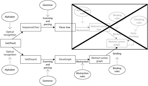
However, when you take a closer look at the various phases of this process, the adjustments that need to be taken are minimal. Figure 7-1 shows the similarities between the recognition processes for a textual and a graphical language.
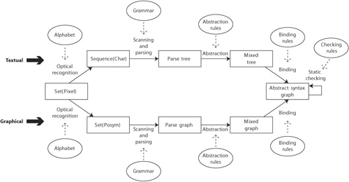
Ultimately, the recognition process of both textual and graphical languages starts with raw data, which consists of a set of pixels: say, a bitmap. Normally, this phase is not included in a discussion about deriving abstract form from concrete form. I include it to be complete and to indicate that what is considered normal is directed by the tools that most people are used to. We are very much used to character-based entry using a keyboard, but what if we were all used to handwriting-recognition tools?
In the textual case, optical character recognition (OCR) is used to derive a sequence of characters. Note that the OCR phase needs knowledge about the type of characters to be recognized. For instance, Chinese characters are quite different from the ones in the Western alphabet. Font and typeface are also important.
In the graphical case, optical recognition is not very well known, yet there are accounts of tools that are able to scan the proverbial table napkin that has been used to record an important discussion [Lank et al. 2001, Hammond and Davis 2002]. As in the textual case, the graphical optical recognition needs to have knowledge of some form of alphabet, the set of glyphs as it is called in this field. This alphabet determines the answers to such questions as, “Does this set of pixels represent a rectangle or four (touching) lines?
The result of this phase is a set of symbols that include some form of knowledge about their position within the set, called the set of positioned symbols, or posyms. This information may be relative to a fixed point (my location is x = 30, y = 28) or relative to each other (my location is above element X, left of element Y). In the community that studies graphical languages, it is considered folklore that a character stream can also be regarded as a set of posyms. Each character can have a maximum of two relative positions: before and after another character.
Background on Compiler Technology
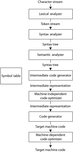
The area of compiler technology is well established. As early as 1972, Aho and Ullman produced a definitive textbook on the subject, which has been revised in 1985 [Aho 1985]—the so-called dragon book because of the dragon on the front cover)—and again in 2007 [Aho 2007]. The figure shown here, from the 2007 edition, explains some basic facts about compiler technology.
A compiler has seven distinguishable phases: lexical analysis (scanning), syntax analysis (parsing), (static) semantic analysis, intermediate code generation, machine-independent code optimization, code generation, and machine-dependent code optimization. In all these phases, a symbol table is available to store and retrieve information about the text being processed. Here, we address only the first three phases: the process from raw input to an in-memory model. Code generation can be regarded as another type of model transformation.
The first phase, scanning, is associated with a regular grammar, which defines the way the characters are bound together to form tokens. The second phase, parsing, is associated with a context-free grammar, which sometimes takes the form of an attributed grammar. An attributed grammar is a context-free grammar in which the nonterminals can hold context-sensitive information in the form of attribute values. The result of this phase is a parse tree, in which the nodes represent the application of the grammar rules.
The third phase, static semantic analysis, is not associated with a specific formalism. In other words, the implementer of the compiler is completely free to process the input and to produce as a result an abstract syntax tree.
According to common understanding, the nodes in the abstract syntax tree represent language concepts rather than grammar rule applications.
The most difficult part of building these three phases is implementing the parsing phase. Several parsing theories have been developed, mostly during the 1960s and 1970s.
1. LL parsing means scanning the input from left to right while building the leftmost derivation, which means that the leftmost nonterminal in the grammar rule is the first to be replaced.
2. LR parsing means scanning the input from left to right, while building the rightmost derivation, which means that the rightmost nonterminal in the rule is the first to be replaced.
3. LALR parsing stands for Look-Ahead Leftmost Reduction. It is an extension of LR parsing that produces more efficient parsers.
Because building a parser by hand is difficult, many tools have been developed that generate parsers. These tools are called parser generators. The most famous example is Yacc [Johnson 1974], other examples are JavaCC [JavaCC 2008], Antlr [Antlr 2008], and SableCC [SableCC 2009]. They take as input a context-free grammar. However, the allowed grammar rules depend on the type of parser produced (LL, LR, or LALR), and the input format is different for all of the parser generators.
In the last two decades advances of compiler construction have been in code generation, particularly with respect to optimization and paralleltarget machines.
The next phase in a compiler is the lexical analysis, or scanning phase, whereby groups of characters are combined to form words. This phase and the next—syntactical analysis, or parsing—are very similar. They are different in the techniques used to implement them and because doing scanning before parsing makes parsing more simple. Examples of generators for scanners and parsers for textual languages are Yacc [Johnson 1974] and Lex [Lesk and Schmidt 1975], Antlr [Antlr 2008] and JavaCC [JavaCC 2008].
For the textual case, the result of this phase is a parse tree. To extend this for graphical languages, the result should be a parse graph. Most nodes in a parse graph are posyms, but some represent larger, compound concepts. All nodes are connected based on either position or on syntactical grouping. For example, in English, book is a noun, a posym, whereas the best-selling, world-famous red book is syntactical grouping called a noun phrase. The syntactical group connects the posyms and other syntactical groups that are part of it. The subgraph that holds only posyms with their positioning information is also known as a spatial relationship graph [Bardohl et al. 1999].
Parse graphs still include nodes that represent purely syntactical elements. In the textual case, keywords and special characters, such as brackets, are present as posyms in the parse graph. In the graphical case, arrows, rectangles, and so on, are present in the parse graph. The first action of the analysis phase is therefore to abstract away from all purely syntactical elements in order to form the abstract syntax graph. In the textual case, the resulting graph is generally known as an abstract syntax tree.
Together with binding and checking, this phase is known as the static semantic analysis, even though this phase has nothing to do with the actual, dynamic semantics of the language, as is nicely explained by Harel and Rumpe [2004].
The abstract syntax graph is not yet the result that is required for further processing, such as code generation or model transformation. The abstract syntax graph may still contain unbound elements, that each represent a reference to another element in the graph but which is not (yet) connected to this other element. These references may refer to parts that might not exist, perhaps owing to a user error or an incomplete specification.
For instance, suppose that a publisher has created a domain-specific language to record books and their authors, according to the metamodel in Figure 7-2(a). Mograms of the language can use either a textual or a graphical concrete syntax, as shown in Figure 7-2(b) and Figure 7-2(c). Any instance of the class Book in a mogram must include a property named author. In the textual concrete syntax (in Figure 7-2(b)), its value is given by a string following the keyword author. In the binding phase, this string value needs to be replaced by, or otherwise bound to, an instance of class Person. This means that somewhere in the mogram, this instance must be present. In the general case, this may not be true.
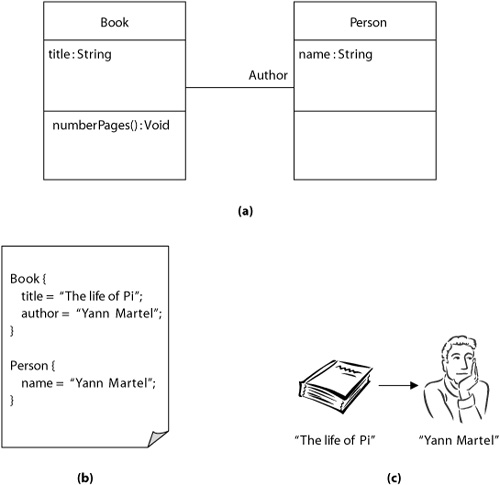
In the graphical concrete syntax (in Figure 7-2(c)), the value of the element author is given directly by the spatial relationship between the arrow leading from the book symbol on the left to the person symbol on the right. In this case, the binding for the property can be deduced from the spatial relationship between the symbols. On the other hand, when two or more symbols representing the same linguistic element are allowed in one diagram or when two or more diagrams are used in a single model, binding may still be necessary. For instance, when the same Person instance symbol appears twice in the diagram, both occurrences must be bound to the same Person instance.
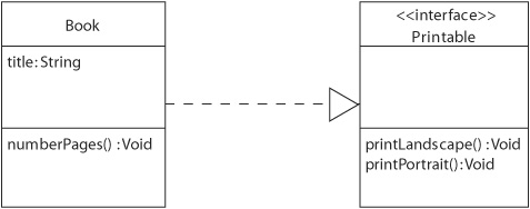
Finally, a number of checks can be performed on the abstract syntax graph. Type checking is a well-known form of checking that can be performed only when all elements have been bound. Control flow analysis is also often done in this phase to recognize unreachable code. Note that although both examples are commonly found in textual languages, this does not mean that similar checks are not required in a graphical language. For instance, according to the UML specification [OMG-UML Superstructure 2005], the arrow in Figure 7-3 may be drawn only between an instance of a BehavioredClassifier and an instance of an Interface. Most UML tools will not allow their users to draw such an arrow in any other case, but when the diagram has been optically recognized from a hand-made sketch (the proverbial napkin), this check still needs to be performed. This scenario does not often take place, since current tools are not powerful enough, but I would really love to include this functionality in my tool set.
Not many people realize that the type of editor you use determines which parts of the recognition process need to be implemented. In general, there are two types of editors, and both types can be used for either textual or graphical languages:
-
A free-format editor, or symbol-directed editor, in which a user may enter at any position any symbol from a predefined alphabet
-
A structure editor, or syntax-directed editor, in which a user may enter only valid grammatical structures
Basic text editors are in the first category. For graphical languages, free-format editors are commonly known as vector graphics editors. These editors facilitate the placing and manipulating of basic graphical shapes—line, rectangle, ellipse—but typically do not support any relationships between the shapes, which is sometimes bothersome when you want to move a symbol around. Think of a UML class symbol that loses all its associations when you move it.
The structure editor did not catch on for textual languages; users found it too restrictive, limiting the programmer’s creativity. Only one particular form of syntax-directed editing for textual languages, namely code-completion, is currently popular. Code-completion editors use knowledge of the grammar and potentially other information from farther down the recognition chain to suggest to users suitable continuations of what they are writing. Users accept this, as it assists them in writing valid expressions while at the same time not restricting them. After all, there are many situations in which a user wants to have the freedom to write invalid expressions.
Considering the experiences with textual language editors, it is surprising that this restrictive type of editor is accepted by users and considered the norm for graphical languages. In my opinion, the reason is that users simply do not have a choice of free-form editors for graphical languages. Almost all computer-aided software engineering (CASE) tools and other graphical-language IDEs offer the user a structure editor. However, some are more restrictive than others. For example, in some UML tools, it is impossible to draw an association between classes from different packages when there is no inclusion relationship between the packages. Other tools allow it and present a warning when the user explicitly asks to check the diagram; yet others do not even provide a warning.
Language environments with structure editors need not include the first phases of the recognition process, especially parsing and abstraction. Depending on their restrictiveness, some of the next phases may also be omitted. For instance, the binding phase is already incorporated in an editor when the user must select from a given list the element that he or she wants to refer to, and there is no other way of creating this reference.
Along with the focus on different types of editors for textual and graphical languages, another form of dissociation occurs. It appears that people working with textual languages have eyes only for scanning and parsing; all other parts of the recognition process are considered to be easy and therefore irrelevant. This blind spot is shown in the box with a large cross in Figure 7-4.
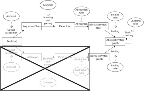
On the other hand, those working with graphical languages seem to have a different blind spot. In this group, scanning and parsing are considered to be irrelevant, as shown in Figure 7-5 in the box with the large cross. (Interestingly, the two blind spots are mutually exclusive, which is probably the reason that these groups, although both involved in language engineering, hardly ever mix.)
Some in this latter group even suggest that specifying concrete syntax is unnecessary. In the words of an anonymous reviewer of an earlier version of this text: “At the low level, information can be exchanged between different computers applications in a concrete-syntax free way using XML, and at the high level, humans can input linguistic utterances into a tool using forms. Thus, the only thing that remains is the need for renderings of models which are meaningful to humans.” Unfortunately, this reviewer seems to forget that the XML schema used is a specification of the interchange format and thus a specification of one of the concrete syntaxes. Furthermore, the way models are rendered is a concrete syntax as well. Should not this be part of a language’s definition? Should a language user not know which symbols are used to show a particular concept?
The only reason people can be this uninterested in concrete syntax is the predominance of syntax-directed editors, which let “humans input linguistic utterances into a tool using forms.” In my opinion, using forms to create and change mograms is not the most convenient way, especially when the mograms become large.
We should put more effort into creating graphical editors that offer more freedom to their users, simply because most users prefer editors that, like basic text editors, offer more freedom. In fact, when you offer your users more freedom in the way they create their mograms, the more likely they will be to use your language.
For instance, a large group of people use Microsoft Visio with their own set of UML symbols. When you use the template shipped with the tool, it becomes another structure editor, but with your own set of symbols, the tool offers you complete freedom. You do not have to link an association to two classes if you don’t want to. The down side is that the output cannot be used for anything else but showing it to another human. The question here is how to transform the output of Visio-like tools to a more usable abstract syntax graph. The answer is: through a recognition process using the rules that link posyms to abstract syntax elements. However, this scenario is not available, because this type of tool interoperability is lacking. I would really love to be able to combine the practicality of Visio for presentations with the power of a code generator working on the same mogram.
So, I would urge you to aim for editors that provide as much freedom as possible to the language user. This holds for both textual and graphical languages, especially for the latter. However, the more freedom you give the language user, the more complex the recognition process becomes, and the more important a good concrete syntax model is. Please make the extra effort; your users will love you for it.
A good description of concrete syntax includes the alphabet of posyms, together with the rules of how to transform a given set of posyms into an abstract syntax graph. A complete concrete syntax description consists of the following:
• An alphabet, which provides the basis symbols
• Scanning and parsing rules, which state how combinations of basic symbols form syntactical constructs
• Abstraction rules, which state which parts of the concrete form do not have a direct counterpart in the abstract form
• Binding rules, which state where and how separate and/or different concrete elements represent the same abstract element
Checking rules should also be included in the language specification, but these are better included in the abstract syntax description (see Section 6.2.4).
Let us look at some examples taken from the well-known UML. First, the concrete representation of a UML association class is a combination of a solid line, a dotted line, and a rectangle representing a class. In the preceding schema, this would be specified by a parsing rule. Also, there should be a scanning/parsing rule that specifies when an end of an association line and adornments, such as the name and multiplicity, are considered to belong together: for instance, by declaring a maximum distance between them. This rule can also be helpful for tools that render UML diagrams. It gives the boundaries of the area in which the adornments may be shown. An example of an abstraction rule would tell you that line and fill colors may be shown but are irrelevant. A binding rule would state that two concrete class symbols represent the same element in the abstract syntax graph as long as they belong to the same package and have the same name. Another binding rule would state that the name of the type of an attribute represents the class with that name.
Of course, your language specification might not include all the rules, and you could still produce a rather satisfactory language and tool set. But you need to consider the following four issues before deciding that a limited concrete syntax description is good enough.
-
A limited concrete syntax description limits the type of tools that can be made available for the language users. In some cases, as when a language is being standardized, the language specification must be completely tool independent. To include a limited concrete syntax description is, in those cases, not the best option. (Unfortunately, it is the common practice.)
-
Language users put up with restrictive tools only because they have no alternative. If your language description allows only for very restrictive tools and some other language comes along that offers much more flexibility to the language user, you will likely lose the battle.
-
Most languages are not only graphical but a combination of graphical elements and text. In these cases, it is very natural to include scanning and parsing rules, at least for the textual parts. Most language users prefer to type a string—for example,
attributeXYZ : classA—that is scanned and parsed to find the separate abstract entities than to select these entities from a list. -
The more elaborate your concrete syntax, the less sophisticated your storage and interchange format can be. Using scanning and parsing tools, which are already provided for the language user, you can always reestablish the abstract form.
The formalism to express the concrete syntax model is metamodeling together with model-transformation rules. The metamodel contains a description of the alphabet and the syntactical constructs that can be built. The transformation rules express how an instance of this metamodel can be mapped on an instance of the abstract syntax model. As formalism for the transformation rules, I used graph transformations, but any other transformation formalism would do. In the next sections, I explain how to create a concrete syntax model and give you an example.
The role of concrete syntax is to represent the mogram to our human senses, usually our eyes. This means that the language engineer must take care in developing a syntax that is pleasant to look at. Of course, beauty is in the eye of the beholder, so no concrete syntax will ever be able to please everyone. Still, the core business of designing concrete syntax is to try and make a notation that many people will like or at least accept.
Explicit methods of how to make a notation that many people will like are not available. It is to a large degree a matter of chance, similar to the way that a piece of music, a book, a movie, or a painting becomes popular. Yet there are a few guidelines on which sources from different fields agree: for instance, the layout of texts [Williams 1994], the writing of texts [Strunk and White 2000], and the design of user interfaces [Cox and Walker 1993].
• Aim for simplicity. An easy-to-learn language is easy to use. The least you should do is omit all needless words and symbols.
• Be consistent. In other words, choose a suitable design and hold to it. Most people think that being consistently bad is better than inconsistency.
• Give the user some flexibility. The cause of a good deal of inflexibility is the making of arbitrary assumptions about how the language user wants the mograms to look.
• Show related concepts in the same way, and keep related concepts together.
• Show unrelated concepts differently and separated.
• Use color sparsely. The use of color is appropriate only when it provides information. In user interface design, the advice is to use no more than four colors. In text layouting, one often sticks to a maximum of two colors.
• Test your design on language users, but don’t follow every piece of advice you get. Keep to the original design, but improve it. Too many cooks spoil the broth.
This section describes the concrete syntax model for the graphical syntax of Alan. A description of the textual concrete syntax model is provided in the next chapter.
Figure 7-6 shows an example of an Alan mogram using the graphical syntax, which is more or less the same as the UML syntax. Actually, the mogram is not completely graphical but rather is a mix of graphical and textual representations. For instance, attributes and operations are shown using a structured text of the well-known format name : type-reference = initial expression and name ( parameters ) : type-reference, respectively, although in the example, the type reference has been omitted because it is void.
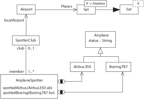
Another textual reference to a type is the text in the overlayed box. A class symbol together with an overlayed box with solid line represents a parameterized class. An overlayed box with a dotted line represents a generic type. The line with the black arrowhead means that the parameterized class uses the generic class as its definition. The text in the solid line box refers to a type variable (X) and to another class (Airplane). Both the type variable and the class must be present elsewhere in the mogram. Binding rules must be given for each of these cases.
However, in this section, I focus on the graphical elements. One such graphical element is the arrow with the little eye on its end, which represents the occurrence of an observe expression.
Figure 7-7 shows some of the elements in Alan’s graphical concrete syntax model (GCSM). As you can see, most elements are simple graphical items: boxes, texts, and lines. You may assume that these graphical items have some way to reveal their spatial relationships, such as the fact that a certain text is within a box and below other text.

The graphical items are all part of the alphabet. In this case, there are only two more complex syntactical elements. One is the TextBox; the other is called ClassBox. A TextBox consists of a text and a box, with the restriction that the text must be contained in the box. Using the spatial information on the bounding box of each element in the alphabet together with the surrounds relationship, we can express this by the following constraint:
context TextBox
inv: box.boundingbox.surrounds(text.boundingbox)
A ClassBox consists of a box, a name text, and, optionally, an attribute text, an operation text, and/or an overlaying textbox. Similar constraints can be defined on the spatial relationships between these parts. For instance, the attribute text must be contained in the box belonging to the same classbox and must be below the name text; similar constraints hold for operation text.
context ClassBox
inv: box.boundingbox.surrounds(name-text.boundingbox)
inv: not attribute-text.oclUndefined()
implies box.boundingbox.surrounds(attribute-text.boundingbox)
inv: box.boundingbox.surrounds(operation-text.boundingbox)
inv: not attribute-text.oclUndefined()
implies attribute-text.below(name-text)
inv: if not attribute-text.oclUndefined()
then not operation-text.oclUndefined()
implies operation-text.below(attribute-text)
else not operation-text.oclUndefined()
implies operation-text.below(name-text)
endif
Together with the metaclasses TextBox and ClassBox, these constraints form the parsing rules in this concrete syntax model. Whether the tooling for this language implements these constraints by allowing only the creation of complete classbox instances or by checking these rules during the parsing phase is not determined or restricted by the way the rules are expressed. Both options are still open.
Similar flexibility is created by the metaclass Line. Because the different line types are represented by attributes (hasEye, etc.), it is possible to create a tool that is able to switch between the different line types. The mapping to the abstract syntax needs to take care of the intended meaning.
In general, there is no direct one-to-one relationship between the elements of a graphical CSM (GCSM) and the elements of the ASM. For instance, a box overlayed by a solid textbox is a representation of an object type, but a box overlayed by a dotted textbox should be mapped to a generic type.
A line with an open arrowhead should be recognized as a supertype relationship between two types. But a line with an eye symbol attached should be mapped to an observer/subject relationship; a line with no attachments should be recognized as a pair of attributes that are each other’s opposite. (I could have used a different GCSM in which these three options were represented by three different classes. In that case, I would have a much simpler job in linking the inheritance symbol, but the other two cases would still be difficult because their recognition involves not one but a pattern of graphical symbols.)
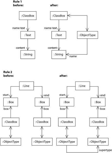
For instance, to map a line representing an association in an instance of the GCSM (the concrete form) to the corresponding elements in an instance of the ASM (the abstract form), we must consider not only the line itself but also the boxes to which the line is attached. These boxes need to have their counterparts in the abstract form before we are able to make a good mapping. Rule 2 in Figure 7-8 specifies this. The rule uses information on the mapping between a classbox and an object type that has been created by the application of rule 1. Both rules are examples of abstraction rules, which indicate the parts of the concrete form that purely concern the visualization, like Line and Box, whereas the contents of a text block cannot be discarded. Note that both rules use a combination of Alan’s GCSM and ASM.
Concrete syntax is always connected to the process of recognizing the abstract form based on a concrete form. This process is well known from compiler technology. Unfortunately, this process also divides the people working on graphical languages from the people working with textual languages. Both groups have mutually exclusive blind spots for parts for the recognition process.
You should specify concrete syntax such that the specification does not put limits on which parts of the recognition process can be implemented. A complete concrete syntax specification consists of an alphabet, scanning and parsing rules, abstraction rules, and binding rules. Although checking rules should also be included in the language specification, they are better included in the abstract syntax model.
A concrete syntax can be written as a metamodel combined with transformation rules that specify how to transform an instance of the metamodel to an instance of the abstract syntax model. The elements from the alphabet are represented as metaclasses, as are the syntactical constructs from the scanning and parsing rules. Their associations and possibly some extra logical constraints specify the scanning and parsing rules. Both abstraction and binding rules are given as transformation rules from the concrete syntax model to the abstract syntax model.
The language users should like what they see in the concrete syntax, although this goal is difficult to accomplish. Do not make too many assumptions about how and what language users think; simply ask them. Build your syntax so that it is consistent, flexible, and simple.