
CONTENTS
12.1 Motivation: The Need for New Scintillators
12.2 Characteristics of Lanthanum Halide Scintillators
12.2.2 Nonproportionality and Energy Resolution
12.2.4 Novel Codoped Lanthanum Halide Scintillators
12.2.5 PMT Selection and Other Readout Devices
12.2.6 Proton and Neutron Activation
12.3 Characteristics of Cerium Tri-Bromide (CeBr3) Scintillators
12.3.1 Proton Activation and Intrinsic Activity of CeBr3 Scintillators
12.3.2 Timing Properties of CeBr3 Scintillators
12.1 MOTIVATION: THE NEED FOR NEW SCINTILLATORS
In developing a new scintillator crystal, a variety of important characteristics need to be addressed, such as the following:
• A high stopping power, related to the scintillator’s density (ρ) and atomic number (Z).
• A high light output; that is, it should be able to readily convert the energy from incident radiation into light.
• Minimal afterglow; that is, the scintillator should be transparent to its own emitting wavelength, ensuring good light collection.
• Good linearity; that is, the conversion of quanta to light should be proportional and uniform throughout the crystal over a wide range of energies.
• Fast response; that is, induced luminescence should decay quickly.
• The material should be robust, low in cost, and available in a range of sizes that make it practical to use for various applications.
Currently, these requirements cannot be met by a single type of scintillator, and therefore interest still exists in developing a scintillator that will match all of the aforementioned criteria. In the 65 years since the discovery of NaI(Tl) for use as a scintillator material by Hofstadter [1], research and development of scintillator materials has led to the discovery of Bi4Ge3O12 (BGO) [2], CsF [3], and BaF2 [4]. High-efficiency bismuth-germanate or BGO crystals have been employed in fields such as high-energy physics [5] and are still commonly used as anti-Compton shields [6] around high-purity germanium detectors (HPGe) in nuclear spectroscopy. CsF and BaF2 crystals allowed the first timing studies to be realized [7,8,9], which had previously been done only with plastic detectors.
The last two decades have seen significant progress in the development of scintillator crystals, driven largely by technological advances and a greater interest in applications. In industry and research, candidates such as lanthanum halide and CeBr3 crystals have emerged as new inorganic crystals with attractive scintillator properties.
12.2 CHARACTERISTICS OF LANTHANUM HALIDE SCINTILLATORS
Inorganic scintillators are the most popular scintillators used in the field of nuclear spectroscopy due to their high light outputs and stopping powers. The scintillation mechanism in inorganic scintillators is due to the electron band structure in the crystals [10]. These types of scintillator crystals are principally alkali-halide crystals containing a small “activator” impurity, which plays an important role in the scintillation mechanism. The activator creates special sites in the crystal lattice, creating energy states within the forbidden gap through which an excited electron can de-excite back to the valence band. The photon generated from this de-excitation is responsible for the visible scintillation light. The de-excitation sites or luminescence centers determine the emission spectrum of the scintillator.
A nuclear or charged particle traversing through the detector medium will form a large number of electron–hole pairs as the electrons move from the valence to the conduction band. Positive holes are ionized by the activator site, which acts as an impurity trap. The electron will continue to pass through the medium until it encounters an ionized activator site, where it will create a neutral configuration with a set of excited energy states. All of these excited energy states are formed at once due to the short travel time of the electron. The time characteristics of the scintillation light emitted by the crystal are associated with the subsequent decay from these excited states [11].
In lanthanum halide crystals, the luminescence is due to the Ce3+ 5d→4f transition, which is shown in Figure 12.1a. “Lattice relaxation” in the crystals causes a minimization in energy, resulting in the excited states populating the band-gap region of the crystal. The difference between the energy absorbed initially (prerelaxation) and emitted (postrelaxation) is called the Stokes shift, which is on the order of 0.55 eV in LaBr3(Ce) [12,13].
Other competing processes exist, such as when the transition from an excited state (created by an electron and impurity trap) to the ground state is forbidden. In this case, an additional amount of energy in the form of thermal excitations allows a transition to a higher-lying state, from which de-excitation is allowed, to the ground state. This results in a slow component to the resulting scintillation light called phosphorescence, a problem in scintillators as it can be a notable source of “afterglow.” Another process involves transitions between some of the excited states in the gap region, which emit no radiation as a result of an electron becoming captured by an impurity trap.
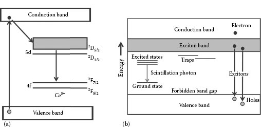
FIGURE 12.1 (a) A schematic representation of the energy levels of the 4f and 5d configurations of Ce3+, responsible for the luminescence in lanthanum halide scintillators. (b) A diagram showing the typical electronic band structure found in scintillators. Variations in the size of the forbidden band-gap region result in different levels of conductivity and are ultimately responsible for each material’s characteristic properties.
An electron–hole pair that travels after the excitation of an electron from the valence to the conduction band is known as an exciton. This delocalized configuration of a hole and electron moves freely within the material from the exciton band until it comes into contact with an activator site, which acts as a generator of electron levels in the forbidden energy-gap region (a schematic diagram of this process is shown in Figure 12.1b). The de-excitation from these states to the ground configuration ultimately results in the creation of scintillation light.
The inorganic halide salts LaCl3 and LaBr3 were first synthesized in 2001 by the Universities of Delft and Bern [14,15,16] and are now made commercially by Saint-Gobain under the product names BrilLanCe® 350 and BrilLanCe® 380, respectively [17]. The crystals are hexagonal in nature (similar in shape to the uranium chloride compound UCl3), with a P63/m space group [18,19]. LaBr3 has a density of 5.07 g/cm3 and a melting point of 783°C, and LaCl3 has a density of 3.64 g/cm3 and melts at 859°C [18]. The low melting points of both compounds allow the crystals to be grown via the Bridgman and Czochralski methods [20], using ultra-pure dry forms of the compounds’ white powder.
The Bridgman crystal-growth technique requires these crystals to be sealed in quartz ampoules. Both LaBr3 and LaCl3 are rare-earth compounds and thus are easily contaminated by moisture and oxygen in the atmosphere. In order to prevent this, the crystal powders are loaded into an ampoule in a nitrogen-purged glove box, where the oxygen and moisture are purged [18]. The ampoule is then lowered into a vertical Bridgman furnace, in which independently controlled heater zones maintain a steady temperature gradient along the entire length of the furnace to facilitate large crystal growth. Failure to maintain an optimal, uniform temperature gradient along the furnace results in the build-up of internal stresses inside the crystal due to non-uniform thermal expansion, which is likely to cause fracturing. This is why lanthanum halide crystals are difficult to grow in large ingots [21]; the largest crystals currently available at the time of writing are Ø3.5” × 8” (89 × 203 mm2) [22]. The build-up of stress during the crystal-making process also makes the initially cylindrical ingots hard to cut, as they are likely to crack and split when cut against their natural cleaving planes. Despite this, different shapes and sizes such as cubes or tapered geometries are readily available. After the crystals are grown, they are subsequently stored under very dry environmental conditions in order to prevent contamination. More information about how these crystals are grown can be found in [18,23,24].
The scintillation properties of both LaBr3 and LaCl3 crystals change with different concentrations of Ce3+, as shown in Table 12.1. Using x-ray-excited luminescence, the variation of the emitting wavelength at various temperatures for different concentrations of Ce3+ doping in LaBr3(Ce) crystals can be studied. Pure LaBr3 crystals were found to have two maxima in their emission light of approximately 340 and 430 nm at 100 K due to self-trapping exciton luminescence [25]. This type of luminescence is responsible for similar bands in other bromides [26,27,28,29] and pure LaCl3 crystals [28,30]. As the temperature is increased to room temperature, however, the maximum near 340 nm disappears and the other maximum at 430 nm shifts to shorter wavelengths, resulting in an x-ray-excited optical luminescence spectrum being dominated by Ce3+ luminescence between 325 and 425 nm. Additional luminescence in LaBr3(Ce:10%) crystals has been reported near 275 nm and is likely to be due to a defect or impurity related to Ce3+ [25].
Lanthanum halide crystals exhibit large amounts of intrinsic activity that limit the use of the crystals in low-counting experiments. These spurious lines arise due to the naturally abundant (0.09%) radioisotope 138La and the α-decay from 227Ac into its daughter nuclides. The former manifests itself in two ways: 66.4% of the time, 138La undergoes electron capture resulting in the population of the 2+ level in 138Ba, which decays by emitting a 1436 keV γ-ray, summed with the 32 and 5 keV coincident x-rays; 33.6% of the time, 138La β− decays into 138Ce, resulting in a β-continuum with an end point of 255 keV and a peak at 789 keV due to the population and subsequent decay of the 2+ level in 138Ce. This 789 keV γ-ray line in the resulting energy spectrum is smeared to higher energies as it is in coincidence with the β-electrons. All of these features are seen clearly below ~1.7 MeV in Figure 12.2, which was acquired over a period of 12 hours.
Above ~1.7 MeV, a large number of broad peaks are present up to ~3 MeV due to the α-decay of 227Ac, which is shown in Figure 12.2. These a energies from the decay of 227Ac actually range from 4 to 8 MeV, meaning that their light is quenched by ~35% [44,45]. A list of the α energies, along with their intensities and calibrated energies as detected in a LaBr3(Ce) scintillator, is shown in Table 12.2. Discrimination between γ and α radiation in both LaBr3(Ce) and LaCl3(Ce) scintillators using pulse-shape analysis techniques has been investigated and has been found to be on the order of a maximum of 10% [46].
TABLE 12.1
Scintillation Properties of Lanthanum Halide Scintillators When Doped with Different Amounts of Ce3+ Compared with Other Readily Available Scintillators
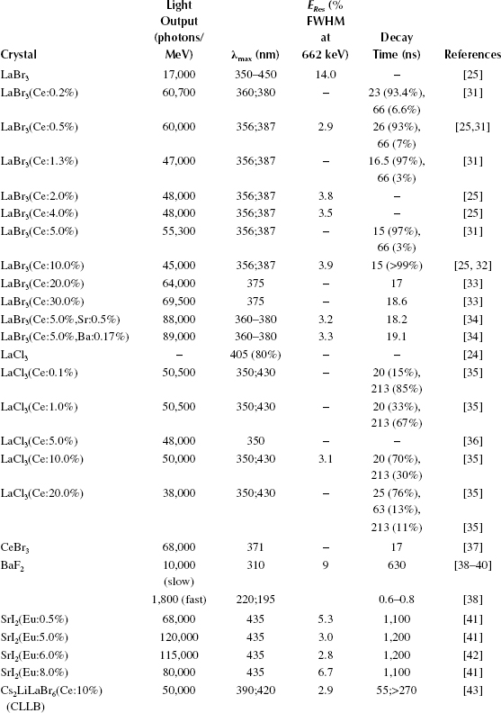
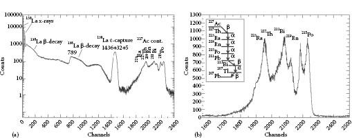
FIGURE 12.2 (a) A γ-ray spectrum showing the intrinsic activity of a single Ø1.5” × 2” LaBr3(Ce) detector. (b) An energy spectrum showing the intrinsic activity of a single #x00D8;1.5” × 2” LaBr3(Ce) detector due to 227Ac contamination. A schematic diagram of the decay path from 227Ac is also shown. The data in both panels was acquired using “singles-mode” triggering over a period of 12 hours, in a lead castle.
The counting rates are approximately 1–2 and 0.1 counts/s/cm3 for contamination from 138La and 227Ac, respectively [108]. In larger, more recently manufactured ingots, the contamination from 227Ac has been reduced significantly in comparison with older crystals due to the purification of raw materials used in the crystal growing process [45,47].
12.2.2 NONPROPORTIONALITY AND ENERGY RESOLUTION
One of the main purposes of a radiation detector is to measure its response to a monoenergetic source of radiation. The resulting distribution of the detected radiation is known as the response function of the detector at that incident energy. A detector with perfect resolution has a δ-like response function. A realistic resolution has a larger variation of incoming pulses for the same incident energy, resulting in a peak with a greater width. The resolution of a detector for a particular energy can be described as being the width of the distribution at a level that is half the maximum (FWHM) of the peak divided by the centroid of the peak (the energy of the detected radiation). One of the dominant sources for fluctuations in the response function arises from statistical noise, which occurs due to a discrete number of charge carriers generated within the detector by a quantum of radiation [48]. The number of discrete carriers fluctuates from event to event, regardless of whether the incident energy is similar, and it can be estimated by describing the formation of each carrier as a Poisson process. Assuming this, the standard deviation of the number of charge carriers, N, is √N.
TABLE 12.2
Decays Responsible for Intrinsic α Radiation in LaBr3(Ce) Scintillators
Decay Path |
α Energy (keV) |
Iγ of Decay (%) |
Calibrated γ-Ray Energy (keV) |
227Th→223Ra |
5757 |
20 |
2015 |
5978 |
24 |
2092 |
|
6038 |
24 |
2113 |
|
223Ra→219Rn |
5607 |
25 |
1962 |
5716 |
52 |
2001 |
|
219Rn→215Po |
6553 |
13 |
2294 |
6819 |
79 |
2387 |
|
215Po→211Pb |
7386 |
100 |
2585 |
211Bi→207Tl |
6278 |
16 |
2197 |
6623 |
84 |
2318 |
Source: Hartwell, J.K. and Gehrke, R.J., Appl. Radiat. Isot., 63, 223, 2005; Quarati, F., et al., Nucl. Instrum. Methods Phys. Res. A, 574, 115, 2007.
Notes: The energies of the α particles in this table have an Iα > 10%. The final column shows the detected energies of these a particles, which are quenched due to the scintillation mechanism by ~35%.
The detector response function can usually be described by the Gaussian function:
(12.1) |
where:
σ = width parameter
xo = peak centroid
A = area of the function
The width parameter σ defines the FWHM of the Gaussian function through the relationship FWHM = 2.35σ, which can be used to determine the Poisson limited resolution as
(12.2) |
This limiting resolution is what gives each detector type its characteristic energy response. If the number of charge carriers (N) increases, then the resolution improves due to a decrease in the limiting resolution. For a RPoisson limit of 1%, the average number of charge carriers ~55,000. This means that, in order to have the best energy resolution available (and thus the smallest limiting resolution possible), one needs to have as many charge carriers as possible. Semiconductor detectors such as CdZnTe and HPGe detectors are popular as these detectors generate a large number of charge carriers. However, discrepancies in the measured values of limiting resolutions have revealed that the total number of charge carriers cannot be completely described by Poisson statistics alone [48]. In an attempt to describe this discrepancy between the statistical fluctuation in the number of charge carriers and the number of charge carriers derived from Poisson statistics, the Fano Factor is introduced. Incorporating this factor of the observed and predicted variance in the number of charge carriers into Equation 12.2, the complete equation describing the nature of the limiting resolution of a detector is now
(12.3) |
The energy resolution of a Ø1” × 1” LaBr3(Ce:0.5%) detector is 2.9% FWHM for a γ-ray photon energy of 662 keV, although this number varies depending on the concentration of the Ce3+ dopand, as shown in Table 12.1.
Many characteristics of a scintillator can influence the resulting energy resolution, such as the variation of the light output of the scintillator with respect to the incident energy (the photopeak position is proportional to the light output). This nonproportionality or non-linear dependence of the light output due to the variation in the absorbed amount of ionization energy, and thus the emitted number of photons per megaelectronvolts at different energies, generally occurs at energies in the x-ray region rather than at energies above 100 keV. The effect nonproportionality has on the resulting energy resolution [49,50,51,52] can be described such that
(12.4) |
where:
RnPr |
= |
effect the nonproportionality of the scintillator has on the energy resolution |
Rinh |
= |
inhomogeneous defects in the scintillator (which can cause fluctuations in the light output) |
RP |
= |
transfer resolution |
RM |
= |
contribution to the energy resolution from the photosensor (i.e., PMT) and Poisson statistics of detected photoelectrons [53,54,55] |
The latter effect on the resolution can be derived from the equation
(12.5) |
where:
v(M) |
= |
variance from the electron multiplication process in the PMT (typically 1+v(M) = 1.25) |
= |
photoelectron yield from the PMT [53] |
For LaBr3(Ce:5%), this photoelectron yield is ~21 keV. Inhomogeneities are responsible for an observed deterioration in the recorded energy resolution with increasing crystal size. In a pure, bare homogeneous crystal we assume the terms Rinh and Rp are negligible (<1% contribution to the overall resolution), leaving only the nonproportionality and photosensor terms RnPr and RM, respectively. Therefore, in order to obtain the best energy resolution possible, the nonproportionality of the crystal must be as low as possible, such that the energy response is mainly reliant on the gain and other characteristics of the PMT.
The processes behind nonproportionality can be explained in the following way. At the beginning of the scintillation process, the efficiency of transporting the charge to the luminescence centers is dependent on the ionization density, which is generated in the scintillator crystal by the interaction of incident radiation. This ionization density increases with the low-energy electrons subsequently generated after an interaction with an x-ray or γ-ray, resulting in an increase of competition with the scintillation process, which lowers the charge transport efficiency to the luminescence centers. This scintillation yield is consequently no longer proportional to the amount of ionizing x-ray or γ-ray radiation, thereby degrading the energy resolution [48,56].
The response of the nonproportional scintillation light in both LaBr3(Ce) and LaCl3(Ce) scintillators has been measured in various studies [51,57,58,59,60] down to a photon energy of 5 keV and an electron energy of 3 keV. Figure 12.3 shows the light yield as a function of γ- and x-ray energies relative to the yield at 662 keV. The nonproportionality of the scintillator response of a Ø25 × 31 mm2 LaBr3(Ce) crystal is compared with that of a NaI(Tl) crystal with similar dimensions. For energies above 1 MeV, the determination of the light yield (particularly for LaBr3(Ce)), might depend on the non-linearity of the PMT. For energies above 100 keV, the LaBr3(Ce) detector seems to be fairly proportional, with a similar degree of proportionality to the NaI(Tl) detector above ~300 keV [61]. At lower energies, the light production in LaBr3(Ce) is much lower with decreasing energy, but is still seen to have a higher degree of light proportionality than NaI(Tl).

FIGURE 12.3 A comparison of the nonproportionality curves measured for both LaBr3(Ce) and NaI(Tl) scintillators, each with crystal dimensions of Ø25 × 31 mm2. (From Syntfeld, A., et al., IEEE Trans. Nucl. Sci., 53, 3938. © (2006) IEEE. With permission.)
Nonproportionality has also been examined for various Ce3+ concentrations in LaBr3 scintillators over a temperature range of 80–450 K [62]. In this study, it was found that for Ce3+ concentrations of 5% and 30%, the best proportionality and energy resolution were recorded at 80 K. For LaBr3(Ce:0.2%), the lowest energy resolution and nonproportionality were obtained at room temperature [62].
The time resolution (pulse-resolving time) of a detector is another important criterion that influences the final choice of scintillator crystal. An ideal timing signal is one whose rising edge is almost vertical, as this gives a more precise moment in time (time pickoff). The criterion for a detector with good timing resolution is how quickly a timing signal is generated and decays, as the duration of the total time signal ultimately dictates the pileup rate. The insensitivity of a detector caused by a long decay time contributes to the dead time and limits the counting rate at which it can be operated.
The timing resolution can be influenced by the size, material, and outer surface condition of the scintillator, as well as by the properties of the light guide, photosensor, and subsequent electronics. Larger crystals will generally have longer timing responses due to the distance the light has to travel through the scintillator. The light guide in the case of lanthanum halides is particularly important, as the crystals are hermetically sealed due to their hygroscopic nature. The effect of a fluctuating gain and the spread in transit time of the accompanying photosensor on the resulting time resolution will be discussed in further detail in Section 12.2.5. In the case of lanthanum halide scintillators, the timing resolution of the detector also depends on the Ce3+ doping concentration, as shown in Figure 12.4.
Typically, the brighter and faster the light pulse generated by the scintillation mechanism in a crystal, the better its ability to resolve the arrival time of two light signals at the end of the scintillator. The uncertainty in the arrival-time difference for these two photons is known as the coincidence resolving time (CRT). In medical applications such as positron emission tomography (PET), the detection of two coincident 511 keV photons caused by electron-positron annihilation forms the basis of this method by using direct coincidences. However, the CRTs of current scintillators used in medical applications, such as LaBr3(Ce), are so good that the emission point of these annihilation photons can be constrained to a small segment along the line of coincidence using time-of-flight (ToF) methods. The CRTs of such detectors are directly responsible for mapping the emission point, where a quicker or smaller CRT between two detectors results in a more accurate location of the initial emission point of the annihilation photons. Typically, the time resolutions in ToF measurements vary between 0.1 and 1 ns for high-quality scintillators. Small LaBr3(Ce) crystals have been tested with silicon photomultipliers (SiPMs) and avalanche photodiodes (APDs) in such medical applications and have been found to give an exceptionally good CRT of ~100 ps, which corresponds to a ToF position resolution of 15 mm [64]. Other studies of CRTs involving small lanthanum halide detectors up to an inch in size can be found in [65,66]. The CRTs of larger LaBr3(Ce) scintillators can be found in Table 12.3.

FIGURE 12.4 The effect of changing the dopant concentration on the timing resolution of a LaBr3(Ce) scintillator. The timing signal shows the prompt detection of two 511 keV annihilation photons in coincidence. (From Glodo, J., et al., IEEE Trans. Nucl. Sci., 52, 5. © (2005) IEEE. With permission.)
TABLE 12.3
CRTs of Detectors for Various Crystal Shapes and Sizes in Picoseconds
Dimensions |
Geometry |
TFWHM at 511 keV |
TFWHM at 1332 keV |
Ø2” × 2” |
Cylindrical |
450 [17] |
300 [67] |
Ø1.5” × 2” |
Cylindrical |
400 [68] |
210 [68] |
Ø1.5” × 1.5” |
Cylindrical |
360 [17] |
180 [67] |
Ø1” × 1” |
Cylindrical |
200 [69] |
|
Ø1” × 1.5” × Ø1.5” |
Conical |
– |
160 [71] |
Notes: Specific details on how the values were obtained and what equipment was used are given in the references cited. The CRT for conical detectors at an energy of 511 keV is not available in the literature at the time of writing.
Timing resolutions are also crucial in nuclear structure physics, as the electromagnetic reduced matrix element B(λL) can be extracted by measuring the half-lives of excited nuclear states. The transition probability TFI(λL) of a state decaying from a state with initial spin J to a final state with spin Ji is given by the formula [72]
(12.6) |
The half-lives of excited states can vary considerably over many orders of magnitude and thus need to be determined using various techniques [73,74]. One of these techniques, the centroid shift method [75, 76, 77, 78], compares the moments of the prompt– and delayed-response functions using the delayed-coincidence method [79]. Until recently, fast coincidences between discrete nuclear states were measured with BaF2 detectors, which have a fast decay time component of 0.6–0.8 ns [38]. However despite having such a fast decay time, the detector suffers from weak light output (1800 photon/MeV [38]) and poor energy resolution of about 9% FWHM for a 662 keV γ-ray [39,40]. The use of superior, readily available scintillators such as LaBr3(Ce) has allowed for the construction of large arrays of fast-timing scintillators [68,80]. It is envisaged that such arrays will measure the half-lives of excited states using the delayed-coincidence method down to tens of picoseconds [67,81,82,83,84,85,86,87,88]. In order to measure the half-lives in this sub-nanosecond regime effectively, it is necessary to have a good understanding of the prompt response function, the width of which depends on the sum of the CRTs between pairs of fast-timing LaBr3(Ce) detectors [81]. The CRTs of various LaBr3(Ce) detectors of different shapes and sizes are shown in Table 12.3.
12.2.4 NOVEL CODOPED LANTHANUM HALIDE SCINTILLATORS
In an effort to improve the currently acclaimed LaBr3(Ce) crystals, ionic co-doping of LaBr3(Ce) was investigated [34]. Small (Ø60 × 80 mm2) LaBr3(Ce: 5%) crystals were co-doped with Sr2+ and Ba2+, resulting in an improvement of the light output of ~25% and a better energy resolution over a dynamic range of 122–2615 keV, due to the increase in the light output combined with improved energy proportionality. Despite this, co-doping LaBr3(Ce:5%) scintillators with 0.5% of Sr and 0.17% of Ba degrades the initial decay time of the LaBr3(Ce:5%) scintillator by 3–4 ns. Deconvolving the time profiles using an impulse-response function, however, results in the extraction of “true” decay times of 18.2 and 19.1 ns for the Sr and Ba co-doped LaBr3(Ce) scintillators, respectively [34]. Similar studies using other co-dopands such as Li+, Na+ Mg2+, and Ca2+ with LaBr3(Ce) scintillators can be found in [89,90].
12.2.5 PMT SELECTION AND OTHER READOUT DEVICES
Selecting a PMT is crucial in order to maintain the anticipated performance of the scintillator by adhering to its intrinsic properties. In order to do this, the PMT has to be compatible with the scintillator in various ways:
• It needs to be matched in light; that is, the peak emission wavelength of the crystal needs to match the highest quantum efficiency offered by the PMT at a similar wavelength.
• It needs to be properly gain-matched in order to maintain linearity in the response.
• The grease used to couple the scintillator and PMT window must ensure maximum light transmission.
It is important to match the peak emission wavelength (λmax) of the PMT with the crystal to ensure that all or most of the light at the emitted wavelength is registered. As we know from Section 12.2, the peak emission wavelength of LaBr3(Ce) and LaCl3(Ce) scintillation light occurs principally between 350 and 420 nm, although changes in the concentration of Ce3+ changes the light output by producing variations in the scintillation process. In order to reduce the loss of the collected scintillation light, a PMT needs to be sensitive to blue ultraviolet (UV) light (with a range of 13–15 μA/lmF), and have a high quantum efficiency (such as a Bi-alkali PMT).
The PMT used with a very high-light-yielding crystal (like LaBr3(Ce) or LaCl3(Ce)), needs to be chosen carefully as space charge effects and saturation can occur, resulting in the degradation of the signal. This can be solved by reducing the gain on the PMT or the number of PMT stages used in the cascade. However, although reducing the bias voltage lowers the gain and current of the PMT by slowing down the electrons during the multiplication process, non-linearity in the generated energy spectrum is likely to occur. Taking the signal from one of the dynode stages (reducing the number of PMT stages used during the multiplication process) is seen to be the most favorable option in avoiding this; however, a greater amount of variance in the signal is produced due to the higher voltages between each dynode stage. Changing the impedance in the voltage divider on the stage used to take the signal is another alternative in trying to improve the energy resolution of a detector [68].
For timing applications, it is important that the selected PMT has a high number of photoelectrons generated by the photocathode and a low spread in gain due to the electron multiplier, and that it limits the transit time jitter associated with the cascading electrons travelling to the first dynode from the photocathode. In some PMTs, a screening grid is placed inside the last dynode, resulting in an improvement in the charge collection due to the reduced ToF of the electrons between the last dynode and the anode [70]. In doing so, a “parasitic” component is induced in the resulting anode signal, as the travelling electrons in the last stage of the PMT increase the triggering point in the fast discriminator due to the charge from this shifted component. This is found to improve the rise time of the anode pulse as the triggering point is much higher in comparison to the main component (generated by the collection of electrons travelling from the last dynode), where the properties of the scintillation detector require only a small fraction of the anode-pulse height in order to achieve the best time resolution.
Optical grease needs to be chosen to allow for maximum light transmission between the PMT window and the crystal (or light guide in the case of hygroscopic LaBr3(Ce) and LaCl3(Ce) scintillators). The coupling grease needs to have a similar refractive index to the crystal or light guide and the PMT window, and it needs to be transparent. Air bubbles need to be eliminated during the coupling process, as these will affect the performance of the detector.
In some applications, the use of other readout devices can have advantages over conventional photosensors such as PMTs. One such field is medical physics, where LaBr3(Ce) and LaCl3(Ce) scintillators are coupled to SiPMs, solid-state sensors that are insensitive to magnetic fields, unlike PMTs. Additionally, SiPMs are transparent to 511 keV γ-rays and are very compact detectors. Such a detector system enables novel designs of compact arrays that are high resolution and allow for depth-of-interaction correction [91]. Moreover, SiPMs are compatible with magnetic resonance imaging (MRI) devices, allowing the possibility of hybrid (PET and MRI) devices to be explored [92,93]. Other applications of SiPMs and LaBr3(Ce) scintillators, such as Compton cameras, can be found in [94].
12.2.6 PROTON AND NEUTRON ACTIVATION
In applications that involve high proton and neutron fluxes (such as space science), the durability of the detector is challenged. In such hostile environments, radiation damage can compromise the performance of the detector and thus needs to be tested.
Exposing LaBr3(Ce) and LaCl3(Ce) scintillators to proton fluxes of 108–12 protons/cm2 results in an activation spectrum due to the proton capture of the constituent elements of the crystal. Although the proton inelastic reaction cross section for the lighter elements (Br and Cl) is less than the 138,139La+p cross section, Br and Cl are more abundant. Consequently, the resulting activation spectrum for a LaBr3(Ce) scintillator is dominated by γ-ray transitions from 77Br and 79Kr [95]. Similarly, the activation spectrum of a LaCl3(Ce) scintillator is dominated by 33Cl and 32Cl. Other nuclides that feature in the activation spectrum include 140Cs and 139Ce from the 138,139La+p reaction channel. Measurements also report that the proton light yield is 44% less than the light yield of γ-rays, due to the higher ionization density that is generated, which quenches the light [45].
Neutron activation of lanthanum halide crystals also occurs due to the large (n, γ) cross sections of stable 139La (9.0 b) and the two stable isotopes in bromine: 79Br and 81Br (11.0 and 2.4 b, respectively) [96,97]. Neutron inelastic scattering of thermal neutrons off these isotopes results in the population of excited levels in 140La and 80,82Br, which subsequently undergo β−-decay and electron capture. Similar results in the case of thermal neutron activation have been found [98].
Pulse shapes of thermal and fast neutron signals have also been compared with those of signals from γ-ray detections in LaBr3(Ce) scintillators using “software CFD,” a method in which the values for the slow and fast components are analyzed in a similar manner to a nuclear instrumentation module (NIM) discriminator module. The fast and slow signals are integrated and the values for the fast and slow components deduced via the zero crossover method. Figure 12.5 shows the sum of the fast and slow components from γ-ray and neutron-anode pulses plotted against the slow component only, showing little or no quenching of the light from the signals of neutrons detected in LaBr3(Ce) scintillators. However, other investigations report that there is modest discrimination between neutrons and γ-rays, which are detected in LaCl3(Ce) scintillators [99]. Further coincidence data with a beamline would aid in verifying these results.

FIGURE 12.5 (See color insert) A spectrum showing a comparison between acquired neutron pulses (which also include coincident γ-rays) from an AmBe source (black) and pulses acquired from a 60Co source (red). No discrimination between both sets of pulse data is possible.
12.3 CHARACTERISTICS OF CERIUM TRI-BROMIDE (CeBr3) SCINTILLATORS
Cerium tri-bromide (CeBr3) crystals were initially developed by Radiation Monitoring Devices in 2004 [33] and offer a cheaper alternative to expensive LaBr3(Ce) and LaCl3(Ce) scintillators. They are currently marketed by Scionix Holland B.V. and can now be grown up to Ø3” × 4” in size [56]. CeBr3 (like lanthanum halide scintillators) is grown via the Bridgman and Czochralski techniques [20] as it melts at 722°C and has a UCl3 lattice structure. Growing the crystals using these melt-based techniques is advantageous as it allows for the growth of larger ingots [100]. The crystal has an asymmetrical hexagonal structure and a tendency to crack due to the build-up of internal stresses from non-uniform thermal expansion inside the crystal, similar to lanthanum halide scintillators. However, compared to the lanthanum in LaBr3(Ce) and LaCl3(Ce) scintillators, the ionic radius of cerium is smaller (122 vs. 120 pm, respectively) [101] and is responsible for CeBr3 having a larger “effective” atomic number. Consequently, the density of CeBr3 is 0.11 g/cm3 larger than LaBr3(Ce:5%) at 5.18 g/cm3 [56]. Due to the hygroscopic nature of the crystal, it has to be prepared using nonaqueous slurries of Al2O3 grit and mineral oil [37]. They are also encapsulated in aluminum containers, with a quartz window for transmitting the light from the scintillator to a photosensor device.
The crystal has a high photon-light yield of 68,000 photons/MeV [37,102,103] (although other findings suggest that the absolute light yield of various large encapsulated CeBr3 crystals varies from 40,000 to 47,000 photons/MeV [56]), with a peak emission wavelength that is reported to be from ~370 nm [37,56] to 390 nm [102], making it compatible with bi-alkali, blue-sensitive PMTs. The luminescence in CeBr3 is similar to that observed in the lanthanum halide crystals, its doublet structure attributed to the transition from the lowest 5d level to the spin-orbit splitting of the 4f2F5/2 and 2F7/2 levels. This doublet structure is seen to be less noticeable in CeBr3 than LaBr3(Ce:5%) [102], which might be due to the smaller lattice configuration and site size, shifting the emission of Ce3+ by several nanometers [56].
The energy resolution of CeBr3 has been measured to be between ~3.4% and ~4.4% (FWHM) [37,104,105]. These values for the energy resolution are similar to energy resolutions for smaller CeBr3 crystal sizes, indicating little loss in the light yield when the size of the crystal is increased. The characterization of these detectors over a dynamic range of γ-ray energies from 81 to 2615 keV, which is determined using 133Ba, 137Cs, 60Co, and 232Th sources, is shown in Figure 12.6a.
The energy dependence of the data in Figure 12.6 can be fitted using the power-law function E−1/2, similar to that used in [106] for LaBr3(Ce) crystals. Reference [104] also reports that CeBr3 is linear over the majority of this energy range, with a linear correlation coefficient of R2 = 0.99975, although an exponential term is needed in order to take into account non-linearity above ~1.7 MeV. Other studies report a similar 1/√E dependence for CeBr3 detectors [56], but add that the nonproportionality component of the overall resolution (defined as RnPr in Equation 12.4) strongly contributes to the limit of the resulting resolution, R. Therefore, the amount of variance in the electron multiplication process of the PMT cannot be attributed entirely to the degradation in the energy resolution [56,90].
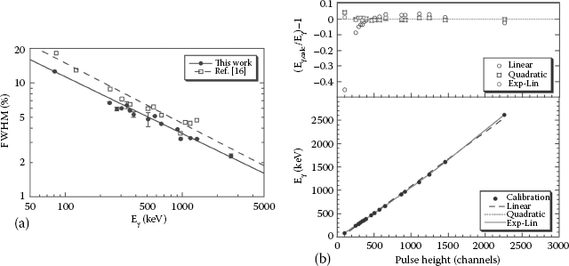
FIGURE 12.6 (See color insert) (a) The measured energy resolutions for γ-ray energies between 81 and 2615 keV. The solid line shows the fit of the power function E−0.4993. The dashed line shows the anticipated E1/2 behavior. (b) The residuals for the different fits to the calibration curves described. (c) The relationship between the pulse height and #x03B3;-ray energy using linear (dashed), quadratic (dotted), and “exponential-linear” (solid) fits. (From Billnert, R., Oberstedt, S., Andreotti, E., Hult, M., Marissens, G., and Oberstedt, A., Nucl. Instrum. Methods Phys. Res. A, 647, 94, 2011.)
Section 12.2.2 commented on how the amount of nonproportionality as a function of energy in the light yield can affect the intrinsic performance of a detector. The light yield of a CeBr3 scintillator is influenced by self-absorption and re-emission processes, which result in the increased likelihood of photon loss within encapsulated crystals, unlike lanthanum halide crystals. Samples of CeBr3 that are not encapsulated are found to have a higher light yield, but without a corresponding improvement in the energy resolution. The light yield from CeBr3 scintillators is very proportional over an energy range of 122–1274 keV, with the nonproportionality of the light yield being ~4% [37]. The contribution to the energy resolution of ~4.0% (typically recorded for these scintillators for an incident energy of 662 keV) is dominated by the photoelectron yield (13 phe/keV for CeBr3 compared to 21 phe/keV reported for LaBr3(Ce:5%) [56]), and the nonproportionality with energy (RnPr). The contribution from the non-proportionality term is greater for CeBr3 than for LaBr3(Ce:5%) [49,53,56]. At present, a model to assess the energy resolution due to the nonproportionality of the crystal is still being devised.
12.3.1 PROTON ACTIVATION AND INTRINSIC ACTIVITY OF CEBR3 SCINTILLATORS
The robustness of CeBr3 scintillators when subjected to high proton fluxes was assessed by replicating energies typically observed from solar events [107], generated by a superconducting cyclotron. The fluxes ranged from 109 to 1012 protons/cm2, where subsequent activation of CeBr3 was found to be similar to that observed in LaBr3(Ce). The resulting spectrum was dominated by 77Kr, 79Kr, and 140Cs from activated bromine and cerium [56]. This study by Quarati et al. also found that during the irradiation of protons on CeBr3, little degradation in the energy resolution or the light yield of the detector was observed [56]. This makes CeBr3 detectors a very promising scintillator to use for future space missions.
Unlike the 138La radioisotope in lanthanum halide detectors, cerium and bromine do not have any long-lived metastable states or radioactive isotopes, and therefore the intrinsic activity in CeBr3 crystals can be ascribed to the decay of 227Ac into its daughter nuclides, similar to that seen in lanthanum halide crystals. The presence of this contamination is likely to be due to the fact that the elements Ac, La, and Ce are chemically similar, or may be due to insufficient purification of the raw materials that go into the making of the crystal. However, the source of the contamination is most likely to originate from 227Ac rather than from raw materials such as 235U ore, due to the structure of the peaks in both lanthanum halide and CeBr3 crystals appearing to be very similar in structure [56]. The levels of 227Ac contamination are largely attributed to the choice of material that is used to grow the crystal, where levels vary from 0.001 cts/s/cm3 to similar levels observed in LaBr3(Ce) scintillators (0.1 cts/s/cm3). However, the level of 227Ac can be reduced by growing the CeBr3 crystals from selected batches, although the long-term availability of batches with low 227Ac cannot currently be guaranteed [56]. Unlike lanthanum halide crystals (which show different levels of intrinsic activity for various crystal sizes due to the escape probabilities and attenuation lengths of the 138La products), the intrinsic activity observed in CeBr3 scintillators is not very dependent on the crystal size [108]. Light from the a radiation registered in the detector due to the intrinsic 227Ac contamination is found to be quenched by 26% when compared to γ radiation. The ratio of this α/γ light yield observed with CeBr3 is thus ~1.33 times lower than that typically observed for LaBr3(Ce) scintillators [56], reinforcing the fact that the charge-transport efficiency to the luminescence centers in CeBr3 is strongly influenced by the higher ionization density.
12.3.2 TIMING PROPERTIES OF CEBR3 SCINTILLATORS
CeBr3 scintillators have been found to be almost as fast as cerium-doped lanthanum halide scintillators, the short lifetime of the emission of Ce3+ luminescence being responsible for the 1/e nature of the decay time constant (τ). For CeBr3, a decay constant of τ = 17 ns has been obtained by fitting an exponential component over the integrated light output and subtracting the background [37]. Similarly, the rise time of the timing signal was found to be 0.7 ns [37]. On average, the decay constant for CeBr3 has been reported to be longer than LaBr3(Ce) due to the self-absorption/re-emission cycle.
Timing resolutions using CeBr3 scintillators have been measured using various types of PMTs to help establish the best combination of scintillator and photosensor. In a study by Fraile et al. [109], a combination of a CeBr3 scintillator with a Hamamatsu (R9779) PMT was found to give a timing resolution (FWHM) of 119 ± 2 and 164 ± 2 ps when used with a reference BaF2 detector at 60Co and 22Na energies, respectively. These values are better than those achieved with a CeBr3-Photonis (XP20D0) detector combination, which was found in the same study to give timing resolutions (FWHM) of 146 ± 2 and 210 ± 2 ps at 60Co and 22Na energies, respectively [109]. This result is interesting as, traditionally, Photonis tubes such as the XP20D0 model (the properties of which are given alongside the Hamamatsu R9779 model in Table 12.4) have been found to perform very well with LaBr3(Ce) crystals in previous studies [70]. Despite the non-linearity of the energy spectrum when these PMTs are used with CeBr3 crystals at an operating voltage above 800 V, the timing resolutions of these scintillators are still 20%–30% worse than results obtained when using a CeBr3 scintillator coupled to a Hamamatsu R9779 PMT [109].
TABLE 12.4
Main Properties of PMTs Used with CeBr3 Crystal
PMT |
τrise (ns) |
FWHM TTS (ns) |
Blue Sensitivity (μA/lmF) |
XP20D0 |
1.60 |
0.52 ± 0.03 [70] |
12.00, 11.60 |
R9779 |
1.80 |
0.25 [110] |
9.55 |
Source: Fraile, L.M., Mach, H., Vedia, V., Olaizola, B., Paziy, V., Picado, E., and Udías, J.M., Nucl. Instrum. Methods Phys. Res. A, 701, 235, 2013. The blue sensitivity for the R9779 is taken from Hamamatsu Photonics. Photomultiplier tube R9779 specifications, 2009.
Notes: The PMTs each have eight stages and borosilicate glass windows. The transit time spread (TTS) is shown in the third column and is given in nanoseconds.
This chapter began by introducing the requirements that need to be met in order to have an ideal scintillator and briefly looked at the history of scintillator development up to the present day. Although not perfect, the lanthanum halide crystals LaBr3(Ce) and LaCl3(Ce) have been shown to be popular crystals in the field of radiation detection. The good energy (2.9% FWHM at 662 keV [25,31]) and excellent timing (~110 ps FWHM at 60Co energies with a Ø1” × 1” crystal [70]) resolutions of these scintillators allow for many opportunities to be realized in medical and space applications, as well as in scientific research, when matched with a good photosensor. However, these crystals suffer from intrinsic activity due to the decay of the radioisotope 138La and a-decay from 227Ac (with rates of approximately 0.7 and 0.1 counts/s/cm3, respectively [45,47]).
More recently, an alternative to lanthanum halide scintillators, CeBr3, has been shown to perform almost as well as its sister crystals. Although CeBr3 does not match the excellent energy resolution offered by LaBr3(Ce) crystals (3.5%–4.5% FWHM at 662 keV [37,104,105]), the timing resolution is comparable (~120 ps FWHM at 60Co energies for a Ø1” × 1” crystal [109]). The most desirable quality of these new scintillators is the absence of a large intrinsic background, making them ideal for low rate/background counting applications.
As technologies and techniques in the field of radiation detection advance, research continues to seek the ideal scintillator detector, with garnet ceramics [42] and other inorganic scintillators (i.e., SrI2(Eu) [41,42], Cs2LiYCl6(Ce) (CLYC) [111,112,113,114,115], Cs2LiLaCl6(Ce) (CLLC) [116], and Cs2LiLaBr6(Ce) (CLLB) [43,116]) presently leading the way.
1. R. Hofstadter, Alkali halide scintillation counters, Phys. Rev., 74:100, 1948.
2. O.H. Nestor and C.Y. Huang, Bismuth germanate: A high-Z gamma-ray and charged particle detector, IEEE Trans. Nucl. Sci., NS-22:68, 1975.
3. M. Moszynski, et al., Properties of CsF, a fast inorganic scintillator in energy and time spectroscopy, Nucl. Instrum. Methods Phys. Res., 179:271, 1981.
4. M. Laval and M. Moszynski, et al., Barium fluoride—Inorganic scintillator for subnano-second timing, Nucl. Instrum. Methods Phys. Res., 206:169, 1983.
5. S.A. Wender, Bismuth germanate as a high-energy gamma-ray detector, IEEE Trans. Nucl. Sci., NS-30:1539, 1983.
6. P.J. Nolan and D.W. Gifford, The performance of a bismuth germanate escape suppressed spectrometer, Nucl. Instrum. Methods Phys. Res. A, 236:95, 1985.
7. M. Moszynski and H. Mach, A method for picosecond lifetime measurements for neutron-rich nuclei, Nucl. Instrum. Methods Phys. Res. A, 277:407, 1989.
8. H. Mach, R.L. Gill, and M. Moszynski, A method for picosecond lifetime measurements for neutron-rich nuclei, Nucl. Instrum. Methods Phys. Res. A, 280:49, 1989.
9. H. Mach, et al., A method for picosecond lifetime measurements for neutron-rich nuclei, Nucl. Instrum. Methods Phys. Res. A, 280:49, 1989.
10. P. Lecoq, A. Annenkov, A. Gektin, M. Korzhik, and C. Pedrini. Inorganic Scintillators for Detector Systems: Particle Acceleration and Detection. Springer-Verlag, Berlin, 2006.
11. G. Knoll. Radiation Detection and Measurement. Wiley, New York, 3rd edn, 232, 2000.
12. J. Andriessen, et al., Lattice relaxation study of the 4f-5d excitation of Ce3+-doped LaCl3, LaBr3, and NaLaF4: Stokes shift by pseudo Jahn-Teller effect, Phys. Rev. B., 76:7, 2007.
13. K.W. Krämer, et al., Development and characterization of highly efficient new cerium-doped rare earth halide scintillator materials, J. Mater. Chem., 16:2773, 2006.
14. J. Andriessen, O.T. Antonyak, and P. Dorenbos, et al., Experimental and theoretical study of the spectroscopic properties of Ce3+ doped LaCl3 single crystals, Opt. Commun., 178:355, 2000.
15. E.V.D. van Loef, P. Dorenbos, C.W.E. van Eijk, K. Krämer, and H.U. Güdel, High-energy-resolution scintillator: Ce3+ activated LaCl3, Appl. Phys. Lett., 77:1467, 2000.
16. E.V.D. van Loef, P. Dorenbos, C.W.E. van Eijk, K. Krämer, and H.U. Güdel, High-energy-resolution scintillator: Ce3+ activated LaBr3, Appl. Phys. Lett., 79:1573, 2001.
17. Saint-Gobain. BrilLanCeTM scintillators performance summary. Saint-Gobain. 2009. http://www.crystals.saint-gobain.com/uploadedFiles/SG-Crystals/Documents/Technical/SGC%20BrilLanCe%20Scintillators%20Performance%20Summary.pdf.
18. W.M. Higgins, et al., Bridgman growth of LaBr3:Ce and LaCl3:Ce crystals for highresolution gamma-ray spectrometers, J. Cryst. Growth, 287:239, 2006.
19. B. Morosin, Crystal structures of anhydrous rare-earth chlorides, J. Chem. Phys., 49(7):3007, 1968.
20. J. Czochralski. Ein neues Verfahren zur Messung des Kristallisationsgeschwindigkeit der Metal, Z. Phys. Chem., 92:219, 1918.
21. P.R. Menge et al., Performance of large lanthanum bromide scintillators, Nucl. Instrum. Methods Phys. Res. A, 579:6, 2007.
22. A. Giaz, et al. 2012 IEEE NSS/MIC Record, 331, 2012.
23. H. Chen, C. Zhou, P. Yang, and J. Wang. Growth of LaBr3:Ce3+ single crystal by vertical Bridgman process in nonvacuum atmosphere, J. Mater. Sci. Technol., 25:753, 2009.
24. Y. Pei, X. Chen, R. Mao, and G. Ren, Growth and luminescence characteristics of undoped LaCl3 crystal by modified Bridgman method, J. Cryst. Growth, 279:390, 2005.
25. E.V.D. van Loef, P. Dorenbos, C.W.E. van Eijk, K.W. Krämer, and H.U. Güdel, Scintillation properties of LaBr3:Ce3+ crystals: Fast, efficient and high-energy-resolution scintillators, Nucl. Instrum. Methods Phys. Res. A, 486:254, 2002.
26. P. Dorenbos, et al., Scintillation properties of RbGd2Br7:Ce3+ crystals: fast, efficient, and high density scintillators, Nucl. Instrum. Methods Phys. Res. B, 132:728, 1997.
27. O. Guillot-Noël, et al. Nucl. Instrum. Methods Phys. Res. B, 132:728, 1997.
28. O. Guillot-Noël, et al., Optical and scintillation properties of cerium-doped LaCl3, LuBr3 and LuCl3, J. Lumin., 85:21, 1999.
29. E.V.D. van Loef, P. Dorenbos, C.W.E. van Eijk, K. Krämer, and H.U. Güdel, Optical and scintillation properties of pure and Ce3+ doped GdBr3, Opt. Commun., 189:297, 2001.
30. E.V.D. van Loef, P. Dorenbos, C.W.E. van Eijk, K. Krämer, and H.U. Güdel, Scintillation properties of LaCl3:Ce3+ crystals: Fast, efficient, and high-energy resolution scintillators, IEEE Trans. Nucl. Sci., NS-48:341, 2001.
31. K.S. Shah, et al., LaBr3:Ce scintillators for gamma-ray spectroscopy, IEEE Trans. Nucl. Sci., 50:2410, 2003.
32. K.S. Shah, et al., High-energy resolution scintillation spectrometers, IEEE Trans. Nucl. Sci., NS-51(5):2395, 2004.
33. K.S. Shah, Cebr3 scintillator. US Patent, 2008. US 7405404.
34. K. Yang, J.J. Buzniak P.R. Menge, and V. Ouspenski. Performance improvement of large Sr2+ and Ba2+ co-doped LaBr:Ce3+ scintillation crystals. Nucl. Sci. Symp. Med. Imag. Conf., 308, 2012.
35. K.S. Shah, et al., LaCl3:Ce scintillator for γ-ray detection, Nucl. Instrum. Methods Phys. Res. A, 505:76, 2003.
36. J.T.M. DeHaas and P. Dorenbos, Advances in yield calibration of scintillators, IEEE Trans. Nucl. Sci., 55:1086, 2008.
37. K.S. Shah, J. Glodo, W. Higgins, E.V.D. van Loef, W.W. Moses, S.E. Derenzo, and M.J. Weber, CeBr3 scintillators for gamma-ray spectroscopy, IEEE Trans. Nucl. Sci., NS-52(6):3157, 2005.
38. Saint-Gobain. Baf2 barium fluoride scintillation material, Saint-Gobain Ceramics and Plastics, Hiram, OH, 2014. http://www.crystals.saint-gobain.com/uploadedFiles/SG-Crystals/Documents/Barium%20Fluoride%20Data%20Sheet.pdf.
39. L.M. Fraile, et al., Fast-timing study of a CeBr3 crystal: Time resolution below 120 ps at 60Co energies, Nucl. Instrum. Methods Phys. Res. A, 701:235, 2013.
40. H. Mach and L.M. Fraile. Hyperfine Interactions, forthcoming, 2012.
41. E.V.D. van Loef, et al., Crystal growth and scintillation properties of strontium iodide scintillators, IEEE Trans. Nucl. Sci., 56:869, 2009.
42. N.J. Cherepy, et al., Scintillators with potential to supersede lanthanum bromide, IEEE Trans. Nucl. Sci., 56:873, 2009.
43. U. Shirwadkar, et al., Scintillation properties of Cs2LiLaBr6 (CLLB) crystals with varying Ce3+ concentration, Nucl. Instrum. Methods Phys. Res. A, 652:268, 2011.
44. J.K. Hartwell and R.J. Gehrke, Observations on the background spectra of four LaCl3 Ce scintillation detectors, Appl. Radiat. Isot., 63:223, 2005.
45. F. Quarati, et al., X-ray and gamma-ray response of a 2”×2” LaBr3:Ce scintillation detector, Nucl. Instrum. Methods Phys. Res. A, 574:115, 2007.
46. F.C.L. Crespi, et al., Alpha–gamma discrimination by pulse shape in LaBr3:Ce and LaCl3:Ce, Nucl. Instrum. Methods Phys. Res. A, 602:520, 2009.
47. B.D. Milbrath, et al., Characterization of alpha contamination in lanthanum trichloride scintillators using coincidence measurements, Nucl. Instrum. Methods Phys. Res. A, 547:504, 2005.
48. G. Knoll, Radiation Detection and Measurement. Wiley, New York, 3rd edn, 330, 2000.
49. P. Dorenbos, J.T.M. DeHaas, and C.W.E. Van Eijk, Non-proportionality in the scintillation response and the energy resolution obtainable with scintillation crystals, IEEE Trans. Nucl. Sci., 42:2190, 1995.
50. E.V.D. van Loef, W. Mengesha, J.D. Valentine, P. Dorenbos, and C.W.E. Van Eijk, Non-proportionality and energy resolution of a LaCl3:10% Ce3+ scintillation crystal, IEEE Trans. Nucl. Sci., 50:155, 2003.
51. M. Moszynski, L.S. Widerski, and T. Szczesniak, et al., Study of LaBr3 crystals coupled to photomultipliers and avalanche photodiodes, IEEE Trans. Nucl. Sci., 55:1774, 2008.
52. M. Moszynski, Inorganic scintillation detectors in γ-ray spectrometry, Nucl. Instrum. Methods Phys. Res. A, 505:101, 2003.
53. I. Khodyuk and P. Dorenbos, Nonproportional response of LaBr3:Ce and LaCl3:Ce scintillators to synchrotron x-ray irradiation, J. Phys. Condens. Matter, 22:485402, 2010.
54. P. Dorenbos, Light output and energy resolution of Ce3+-doped scintillators, Nucl. Instrum. Methods Phys. Res. A, 486:208, 2002.
55. P. Dorenbos, Fundamental limitations in the performance of Ce3+-, Pr3+-, and Eu2+-activated scintillators, IEEE Trans. Nucl. Sci., 57:1162, 2010.
56. F.G.A. Quarati, et al., Scintillation and detection characteristics of high-sensitivity CeBr3 gamma-ray spectrometers, Nucl. Instrum. Methods Phys. Res. A, 729:596, 2013.
57. A. Owens, A.J.J. Bos, S. Brandenburg, and P. Dorenbos, et al., The hard x-ray response of Ce-doped lanthanum halide scintillators, Nucl. Instrum. Methods Phys. Res. A, 574:158, 2007.
58. S. Kraft, E. Maddox, and A. Owens, et al., Development and characterization of large La-halide gamma-ray scintillators for future planetary missions, IEEE Trans. Nucl. Sci., 54:873, 2007.
59. C. D’Ambrosio, F. de Notaristefani, G. Hull, V.O. Cencelli, and R. Pani, Study of LaCl3:Ce light yield proportionality with a hybrid photomultiplier tube, Nucl. Instrum. Methods Phys. Res. A, 556:187, 2006.
60. S.A. Payne, N.J. Cherepy, G. Hull, J.D. Valentine, W.W. Moses, and W.-S. Choong, Nonproportionality of scintillator detectors: Theory and experiment, IEEE Trans. Nucl. Sci., 56:2506, 2009.
61. A. Syntfeld, et al., Comparison of a LaBr3 (Ce) scintillation detector with a large volume CdZnTe detector, IEEE Trans. Nucl. Sci., 53:3938, 2006.
62. I.V. Khodyuk, F.G.A. Quarati, M.S. Alekin, and P. Dorenbos, Energy resolution and related charge carrier mobility in LaBr3:Ce scintillators, J. Appl. Phys, 114:123510, 2013.
63. J. Glodo, et al., Effects of Ce concentration on scintillation properties of LaBr3:Ce, IEEE Trans. Nucl. Sci., 52:5, 2005.
64. D.R. Schaart, et al., LaBr3:Ce and SiPMs for time-of-flight PET: Achieving 100 ps coincidence resolving time, Phys. Med. Biol., 55:N179, 2010.
65. I. Deloncle, et al., Fast timing: Lifetime measurements with LaBr3 scintillators, J. Phys. Conf. Ser., 205:012044, 2010.
66. C.P. Allier, et al., Readout of a LaCl3(Ce3+) scintillation crystal with a large area avalanche photodiode, Nucl. Instrum. Methods Phys. Res. A, 485:547, 2002.
67. N. Mărginean, et al., In-beam measurements of sub-nanosecond nuclear lifetimes with a mixed array of HPGe and LaBr3:Ce detectors, Eur. Phys. J. A, 46:329, 2010.
68. O.J. Roberts, et al. Development of a LaBr3(Ce) fast-timing array for FAIR. EPJ Web Conf., 63, 2013.
69. J.-M. Régis, et al., The mirror symmetric centroid difference method for picosecond lifetime measurements via γ–γ coincidences using very fast LaBr3(Ce) scintillator detectors, Nucl. Instrum. Methods Phys. Res. A, 622:83, 2010.
70. M. Moszynski, et al., New Photonis XP20D0 photomultiplier for fast timing in nuclear medicine, Nucl. Instrum. Methods Phys. Res. A, 567:1, 2006.
71. L.M. Fraile, et al. Fast Timing Collaboration. Fast Timing Studies at ISOLDE: Highlights and Perspectives. Universidad Complutense, Madrid, 2009. https://indico.cern.ch/event/67060/session/8/contribution/36/material/slides/0.pdf.
72. K.S. Krane. Introductory Nuclear Physics. Wiley, New York, 1988.
73. P.J. Nolan and J.F. Sharpey-Shafer, The measurement of the lifetimes of excited nuclear states, Phys. Rep., 42:1, 1979.
74. A.Z. Schwarzschild and E.K. Warburton, The measurement of short nuclear lifetimes, Ann. Rev. Nucl. Sci., 18:265, 1968.
75. Z. Bay, Calculation of decay times from coincidence experiments, Phys. Rev., 77:419, 1949.
76. W. Andrejtscheff, et al., The generalized centroid shift method for lifetime measurements in heavy ion reactions, Nucl. Instrum. Methods Phys. Res. A, 204:123, 1982.
77. P. Petkov, et al., Complex time distributions from isomers in cascade: A case in 176Lu, Nucl. Instrum. Methods Phys. Res. A, 321:259, 1992.
78. H. Mach, et al., Retardation of B(E2; 01+ → 21+) rates in 90–96Sr and strong subshell closure effects in the A ~ 100 region, Nucl. Phys. A, 523:191, 1991.
79. P.H. Regan, et al., Precision lifetime measurements using LaBr3 detectors with stable and radioactive beams, EPJ Web Conf., 63, 2013.
80. O.J. Roberts, et al., A LaBr3:Ce fast-timing array for DESPEC at FAIR, Nucl. Instrum. Methods Phys. Res. A, 748:91, 2014.
81. J.-M. Régis, et al., The generalized centroid difference method for picosecond sensitive determination of lifetimes of nuclear excited states using large fast-timing arrays, Nucl. Instrum. Methods Phys. Res. A, 726:191, 2013.
82. T. Alharbi, et al., Electromagnetic transition rates in the N = 80 nucleus 58138CeCe, Phys. Rev. C, 87:014323, 2013.
83. T. Alharbi, et al., Gamma-ray fast-timing coincidence measurements from the 18O+18O fusion-evaporation reaction using a mixed LaBr3-HPGe array, Appl. Radiat. Isot., 70:1337, 2012.
84. P.J.R. Mason, et al., Half-life of the I-pi=4(-) intruder state in P-34: M2 transition strengths approaching the island of inversion, Phys. Rev. C, 85:064303, 2012.
85. P.J.R. Mason, et al., Half-life of the yrast 2+ state in 188W: Evolution of deformation and collectivity in neutron-rich tungsten isotopes, Phys. Rev. C, 88:044301, 2013.
86. S. Kisyov, et al., Fast-timing measurements in 95,96Mo, J. Phys. Conf. Ser., 2012.
87. S. Kisyov, et al., In-beam fast-timing measurements in 103,105,107Cd, Phys. Rev. C, 84, 2011.
88. O.J. Roberts, et al., Half-life measurements of excited states in 132Te, 134Xe, Acta Phys. Pol., B44, 2013.
89. M.S. Alekhin, et al., Improvement of y-ray energy resolution of LaBr3:Ce3+ scintillation detectors by Sr2+ and Ca2+ co-doping, App. Phys. Lett., 102:161915, 2013.
90. M.S. Alekhin, D.A. Biner, K.W. Krämer, and P. Dorenbos, Improvement of LaBr3:5%Ce scintillation properties by Li+, Na+, Mg2+, Ca2+, Sr2+, and Ba2+ co-doping, J. Appl. Phys., 113:224904, 2013.
91. S. Espana, et al., Performance evaluation of SiPM photodetectors for PET imaging in the presence of magnetic fields, Nucl. Instrum. Methods Phys. Res. A, 613:308, 2010.
92. C. Catana, et al., Simultaneous acquisition of multislice PET and MR images: Initial results with a MR-compatible PET scanner, J. Nucl. Med., 47:1968, 2006.
93. M.S. Judenhofer, et al., Simultaneous PET-MRI: A new approach for functional and morphological imaging, Nat. Med., 14:459, 2008.
94. G. Llosa, et al., First Compton telescope prototype based on continuous LaBr3-SiPM detectors, Nucl. Instrum. Methods Phys. Res. A, 718:130, 2013.
95. E.-J. Buis and F. Quarati, et al., Proton induced activation of LaBr3:Ce and LaCl3:Ce, Nucl. Instrum. Methods Phys. Res. A, 580:902, 2007.
96. O.J. Roberts, et al. Neutron response of 1.5” LaBr3:Ce crystal scintillators for PARIS. 2008. http://paris.ifj.edu.pl/documents/detectors/Ce.pdf.
98. A.A. Naqvi, et al., Detection efficiency of low levels of boron and cadmium with a LaBr3:Ce scintillation detector, Nucl. Instrum. Methods Phys. Res. A, 665:74, 2011.
99. C. Hoel, et al., Pulse-shape discrimination of La halide scintillators, Nucl. Instrum. Methods Phys. Res. A, 540, 2005.
100. J.C. Brice. Crystal Growth Processes. Blackie Halsted, London, 1986.
101. R.D. Shannon, Revised effective ionic radii and systematic studies of interatomic distances in halides and chalcogenides, Acta Crystallogr. A32:751, 1976.
102. W. Drozdowski, P. Dorenbos, A. Bos, G. Bizarri, A. Owens, and F. Quarati, CeBr3 scintillator development for possible use in space missions, IEEE Trans. Nucl. Sci., NS-55(3):1391, 2008.
103. P. Guss, M. Reed, D. Yuan, A. Reed, and S. Mukhopadhyay, CeBr3 as a room-temperature, high-resolution gamma-ray detector, Nucl. Instrum. Methods Phys. Res. A, 608(2):297, 2009.
104. R. Billnert, S. Oberstedt, E. Andreotti, M. Hult, G. Marissens, and A. Oberstedt, New information on the characteristics of 1in.×1in. cerium bromide scintillation detectors, Nucl. Instrum. Methods Phys. Res. A, 647:94, 2011.
105. F. Quarati. LaBr3 gamma-ray spectrometers for space applications. PhD thesis, Technische Universiteit Delft.
106. M. Ciemala, et al., Measurements of high-energy-rays with detectors, Nucl. Instrum. Methods Phys. Res. A, 608:76, 2009.
107. A. Owens, et al., Assessment of the radiation tolerance of LaBr3:Ce scintillators to solar proton events, Nucl. Instrum. Methods Phys. Res. A, 572:785, 2007.
108. F.G.A. Quarati, et al., Study of 138La radioactive decays using LaBr3 scintillators, Nucl. Instrum. Methods Phys. Res. A, 683:46, 2012.
109. L.M. Fraile, H. Mach, V. Vedia, B. Olaizola, V. Paziy, E. Picado, and J.M. Udías, Fast timing study of a CeBr3 crystal: Time resolution below 120ps at 60Co energies, Nucl. Instrum. Methods Phys. Res. A, 701:235, 2013.
110. Hamamatsu. Photomultiplier tube R9779 specifications. Hamamatsu Photonics, Iwata City, Japan, 2012. http://www.hamamatsu.com/resources/pdf/etd/R9779_TPMH1297E06.pdf.
111. C.M. Combes, et al., Optical and scintillation properties of pure and Ce3+-doped Cs2LiYCl6 and Li3YCl6:Ce3+ crystals, J. Lumin., 82:299, 1999.
112. E.V.D. van Loef, et al., Optical and scintillation properties of Cs2LiYCl6:Ce3+ and Cs2LiYCl6:Pr3+ crystals, IEEE Trans. Nucl. Sci., 52:1819, 2005.
113. A. Bessiere, et al., Luminescence and scintillation properties of CS2LiYCl6:Ce3+ for γ and neutron detection, Nucl. Instrum. Methods Phys. Res. A, 537:242, 2005.
114. A. Bessiere, et al., New thermal neutron scintillators: Cs2LiYCl6:Ce3+ and Cs2LiYBr6:Ce3+, IEEE Trans. Nucl. Sci., 51:2970, 2004.
115. J. Glodo, et al., Scintillation properties of 1 inch Cs2LiYCl6 crystals, IEEE Trans. Nucl. Sci., 55:1206, 2008.
116. J. Glodo, et al., Selected properties of Cs2 LiYCl6, Cs2 LiLaCl6, and Cs2 LiLaBr6 scintillators, IEEE Trans. Nucl. Sci., 58:333, 2011.