
Modern Semiconductor Pixel Detectors Used as Radiation Monitors |
CONTENTS
1.4 New Radiation Environment Monitor Based on Pixel-Detector Technology
1.4.1 Charge-Integrating Devices
1.4.2 Single-Quantum Counting Devices
1.5 Advantages of Pixel Detectors
1.6 Future of Radiation Monitors Based on Pixel Detectors
In our daily lives, radiation cannot be seen,* smelled, or heard; that might be why it retains an aura of mystery. The truth is, radiation is all around us, and we are exposed to it on a daily basis. Indeed, the evolution of life on Earth may have actually required radiation [2]. However, when radiation levels exceed values to which the human body is adapted, it can present significant health hazards [3]. Generally speaking, radiation measurement and monitoring on Earth is required only if some special event occurs, or in places where we deal with increased radioactivity on a daily basis (e.g., nuclear power plants). There is, however, a place where radiation monitoring is a necessity—space [4]. Normally, humankind is protected from the radiation found throughout space by Earth’s atmosphere and magnetic field. What would happen to us if we did not have this protection? Also, can we establish and minimize the risks associated with exposure to space radiation? These questions have to be answered if humankind is to expand its influence to other planets or to the stars beyond.
Radiation dosimetry is the science dealing with the accurate determination of the energy deposited in a material, such as living tissue, by radiation. Properly establishing the threat that radiation, ionizing or otherwise, poses to humans is a daunting task due to the complexity of the interaction between radiation and matter. Not only are there many different types of radiation, but the radiation in space has a continuous energy spectrum, ranging from energies that can be shielded by a single piece of paper to incredible energies that represent orders of magnitude higher than those we can create in the largest accelerators on Earth [5,6]. How radiation interacts with matter also depends on the material composition, and thus a detailed calculation is needed when information from a silicon-based detector is used to assess effects on human tissue.
Such complexities make dosimetry a complex, interdisciplinary field, wherein there is always a demand for new radiation monitors. Developments in microelectronics open new possibilities in this area, and development of leading-edge radiation monitors based on pixel-detector technologies is currently under way. These new monitors will be used for future crewed space missions, as well as for portable radiation monitors, which may be used both within the crewed space program and back on Earth.
Over the last several decades, since humans first ventured into space, our understanding of the ionizing radiation environment near Earth and within the solar system has expanded, but this understanding is far from complete. Several models for the radiation spectra at Earth have been developed, based on data gathered both from terrestrial measurements and from satellites in orbit around our planet as well as from interplanetary probes [7,8,9]. One of the biggest obstacles for all future crewed missions traveling beyond the protection of Earth’s magnetic field will be the radiation environment [10]. Without the protection of Earth’s magnetic field and atmosphere, radiation represents a very significant threat to astronauts’ health. Moreover, the radiation in space is not constant in time. For example, solar particle events (SPEs) that erupt from the sun can significantly increase the radiation in the interplanetary environment and have the potential to seriously impact, or possibly cause the death of, insufficiently protected astronauts on interplanetary or deep-space missions. Thus, fast and precise measurement of the radiation field is one of the priorities for all future missions.
Earth’s magnetic field and atmosphere provide terrestrial life with a robust shield from cosmic and solar radiation, though relatively small amounts of such radiation do reach sea level. For example, muons and neutron cascades are measurable, along with a range of other particle types, at ground-level observation stations. As altitude increases, the amount of matter for particles to interact with decreases. Hence, the dose from ionizing radiation increases with altitude, and the background radiation dose at sea level is lower than the background measured at higher elevations [11]. The surface radiation levels also decrease with latitude, the equatorial regions having lower surface radiation levels.
Earth’s magnetic field can be thought of as a dipole field, which is tilted and offset relative to Earth’s spin axis. Charged particles become trapped in the geomagnetic field within regions known as the Van Allen Belts. The offset and tilt of the geomagnetic field give rise to the South Atlantic Anomaly, a region of increased radiation in low Earth orbit (LEO) where the inner Van Allen Belt, containing primarily trapped protons, is nearest the surface of Earth [12,13].
At LEO altitudes (altitudes between 160 and 2000 km), the radiation field has a distinct separation in components based on geographic location. Trapped electrons populate high-latitude regions over North America and above the Southern Indian Ocean, as well as in regions near the magnetic poles. These are regions where the trapped electrons can reach LEO altitudes as they bounce between north–south magnetic mirror points. These regions are also populated by those galactic cosmic rays with sufficient energy to penetrate the magnetic field.
Closer to the planet’s equator, the magnetic field is more effective at similar altitudes, resulting in only the higher-energy cosmic rays being able to penetrate to LEO altitudes. In addition, geomagnetic cusp regions allow access of solar particles to LEO altitudes. Geomagnetic cusp regions are regions at higher latitudes where geomagnetic field lines have been opened to the interplanetary magnetic field through interaction with the solar wind [14,15].
Solar phenomena, such as coronal mass ejections (CMEs) and proton events, also have an impact on radiation components in LEO. CMEs are shock fronts in the interplanetary medium composed of plasma swept up following a solar eruption. When such a shock passes Earth, it can cause disturbances in the geomagnetic field, which have the ability to cause variations in the radiation belt location and composition. The result is a widening of the areas of effect associated with the magnetic field and, in some cases, the formation of temporary belts of trapped particles [12].
SPEs are also a concern at LEO. High-energy protons and other solar products are accelerated toward Earth as a result of disturbances or eruptions in the Sun’s corona [16,17]. The high-energy protons arrive at Earth within minutes to hours and can cause a dramatic increase in both the energy spectrum and in the overall proton flux [18]. If a vehicle is not well shielded by the geomagnetic field, SPEs can result in greatly increased radiation exposure relative to quiescent periods [16,19]. For deep-space crewed missions outside Earth’s magnetic field, SPEs can represent potentially fatal radiation risks in the absence of sufficient shielding to protect the crew.
Finally, galactic cosmic rays (GCR) comprise a fully ionized background in the space radiation field with a component that extends well into relativistic energies and a nuclear composition that ranges from electrons and protons through iron and beyond. Thought to have been initially accelerated in supernova remnants and other interstellar media and further accelerated through various processes during propagation to our solar system, these relativistic ions are the most difficult portion of the space radiation field against which to shield [16,20]. While GCRs are a relatively small portion of the particle flux in LEO, it represents a large fraction of the biologically significant radiation exposure to spacefarers. This, combined with the difficulty in shielding against GCRs, presents a unique problem as humans transition into crewed interplanetary exploration [16,21].
In summary, any generic radiation monitor that attempts to assess the content of the radiation environment needs to be sufficiently sensitive to nuclei from protons through iron with energies from tens of megaelectronvolts to fully relativistic, as well as lower-energy electrons up to tens of megaelectronvolts. No mention has been made of neutrons, as there are essentially no primary neutrons, but there are albedo neutrons that are produced by interactions of the primary nuclei with other objects like Earth’s atmosphere and planetary surfaces, and there are also secondary neutrons produced in interactions with the spacecrafts themselves.
Current radiation monitoring hardware used in space exploration falls into two categories: passive and active. Passive instrumentation, such as thermoluminescent detectors, collects energy from the radiation field to which it is exposed and does not provide a signal until the detector is processed to extract the desired latent information [22]. Active instrumentation, however, provides a data stream that can be used immediately or stored for future analysis.
Passive detectors used in space dosimetry applications are well understood and are heavily relied upon in operational radiation dosimetry, especially to provide statutory records. The methods and materials have been well developed, and the material responses to radiation are understood to a high degree [23]. This translates into a reliable set of results with which to assess radiation exposures and related health risks. The downside, however, is the significant time delay between the exposure and obtaining the result, and the nonlinearity of the response to the details of the composition of the incident radiation. This is especially true for spaceborne instrumentation, which may be deployed for months before the data are extracted from the detector.
Active instrumentation based on proportional counters, such as the tissue equivalent proportional counter (TEPC), which is currently used for operational dosimetry on the International Space Station (ISS), is built on well-developed instrumentation technology [22,24]. While these instruments give real-time (or nearly so) feedback relating to the radiation exposures in a vehicle, such instruments rely on estimation of linear (or lineal) energy transfer (LET) into dose and dose equivalent values for use in assessing the dosimetric quantities of interest in the space radiation environment. The limitation is that TEPCs have a sensitive gas volume that is typically cylindrical with no tracking information. The net output is simply the total integrated charge deposited in the gas, which does directly yield the absorbed dose in an equivalent mass of tissue. However, without any measurement of the path length, only average or mean LET can be estimated with assumptions like isotropic illumination. The benefit of TEPCs is that no correction for the material is needed as it is “tissue equivalent,” unlike Si-based detectors.
Existing instrumentation based on solid-state particle telescope technology provides time-resolved energy and charge spectra of the local radiation fields. However, such instruments have large mass and power-draw requirements, which impact the overall launch and power budget available to space-based platforms.
Modern pixel-detector technology presents a novel approach to space radiation dosimetry [25]. Pixel-detector hardware can be calibrated to provide segmented-grid measurements of energy deposition across a solid-state detector for planar-type detectors, or throughout the detector volume for three-dimensional pixel-detector technologies. Such detectors are small and low-power devices (approximately 2 cm2 and 0.5 W, respectively, for Timepix silicon detectors) in comparison to the cubic feet and tens of watts required to operate existing active space radiation detectors.
In addition to size and power advantages, the spatial and temporal resolution provided by existing and emergent pixel-detector technologies provides information previously not available to active detectors in a space environment. The spatial distribution of energy deposition is available within the pixel-detector data, and coupling the spatial information with the temporal information allows individual particle tracks to be identified and analyzed, potentially providing the most complete characterization of the radiation field.
1.4 NEW RADIATION ENVIRONMENT MONITOR BASED ON PIXEL-DETECTOR TECHNOLOGY
The great advances in microelectronics allow the creation of more sophisticated structures in the front-end electronics of modern pixel detectors. Although many institutions and companies are developing new devices, they all can be divided into two categories—charge-integrating devices or single-quantum-counting devices. These two approaches are quite different, and both have pros and cons.
1.4.1 CHARGE-INTEGRATING DEVICES
Examples of charge-integrating devices are charge-coupled devices (CCDs) (such as those found in earlier digital cameras), flat panels, and complementary metal–oxide–semiconductor (CMOS) pixel detectors. These devices integrate deposited charge within each pixel during measurement. This charge is then measured on the device output capacitance. The CCD was invented in 1969 at AT&T Bell Labs by Willard Boyle and George E. Smith [22]. The principle of the device is rather simple; a CCD is made of silicon, where each pixel contains a potential well. When the charge is collected in the pixel, it is stored in this well. When the device is read out, the charge is shifted along the row to the charge amplifier and the other read-out electronics. The output of the detector is the analog signal corresponding to the total charge integrated in the pixel during measurement.
Flat-panel detectors are based on the technology used in LCD monitors. A scintillator layer made of gadolinium oxysulfide or cesium iodide converts x-rays to visible light. This visible light is then detected by an array of pixels with photodiodes made of amorphous silicon placed on glass. The advantage of this type of detector is the possibility of building detectors with large areas. The disadvantage is limited spatial resolution resulting from the nonzero thickness of the scintillator.
Because the output of charge-integrating devices is an analog signal, such devices are not energy sensitive; that is, they cannot be used for energy measurements.
The latest CMOS pixel devices are a combination of bulk sensor material with embedded transistor structures that can store the collected charge locally. They can be addressed in sequence to supply the charge to a common read-out bus in sequence, where the analog charge is digitized externally. These devices still digitize the collected charge externally, but the charge from each pixel is provided directly to the external digitizer without being shifted through the intervening pixels.
1.4.2 SINGLE-QUANTUM COUNTING DEVICES
Single-quantum counting (SQC) devices differ from charge-integrating devices in many significant ways. Charge-integrating devices collect the charge throughout the acquisition duration. This charge is processed and analyzed, giving rough information about how many quanta were detected (at least relative to other pixels). SQC devices, as the name indicates, process the signal from each quantum separately. This is a result of SQC devices having more sophisticated electronics positioned in each pixel. The added front-end electronics process signals from each event and convert them into a digital number representing the event. The number of measured quanta is exact.*
Hybrid detector technology, developed within the field of high-energy physics, is a new detector concept wherein the detector is composed of two parts—a sensor and a read-out chip. These two components are bump bonded together, and both can be optimized separately with respect to the application. Ionizing particles crossing the sensor component create electron–hole pairs. The electrons and holes are separated by an applied reverse bias voltage, allowing the charge carriers to be collected by the read-out chip. The collected charge is then processed in the front-end electronics of the appropriate pixels.
One of the advantages of the hybrid technology is that the sensor can be made from a different material than the read-out chip according to the application requirements. For example, x-ray imaging could benefit from the use of cadmium telluride (CdTe) sensors, which have much higher detection efficiency than silicon for x-rays above a few kiloelectronvolts. Silicon sensors can be made much thicker and from silicon with different properties (highly resistive silicon) as compared to common monolithic detectors. Figure 1.1 shows a schematic illustration of a hybrid pixel detector.

FIGURE 1.1 (See color insert) The hybrid detector consists of two independent parts: a sensor and a read-out chip. These two parts are joined together by bump bonding. The advantage of this technology is that the sensor material can be tailored to the specific application.
The Timepix detector is semiconductor pixel detector based on the hybrid detector technology (Figure 1.2) [26]. It was developed by the Medipix2 collaboration, consisting of more than 20 institutions around the world and was manufactured by IBM.
The sensor is equipped with a single common backside electrode, while the frontside is composed of a matrix of electrodes (256 × 256 square pixels with a pitch of 55 μm), giving it an active area of 2 cm2. Each pixel on the sensor is bump bonded to the pixel pad on the read-out chip. This arrangement means that every pixel behaves as an independent detector, each with its own devoted read-out electronics. The front-end electronics within each pixel are divided into two parts: analog and digital. The analog portion collects, amplifies, and shapes the signal and is able to process signals from either electrons or holes. Typically, detectors bump bonded to either 300 or 500 μm thick n-type silicon sensors are used, resulting in the collection of holes to produce the signal. Hence, all signals from the preamplifier shown hereafter are negative. It should also be mentioned that the term time over threshold (TOT) is commonly used, independent of the sign of the charge collected.
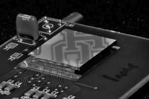
FIGURE 1.2 The detail of the Medipix/Timepix detector with a 1 mm Si sensor mounted on a standard probe card. The sensor backside is typically covered by a thin aluminum layer to provide better ohmic contact. The aluminum layer here reflects the logo of the University of Houston, which, together with the Institute of Experimental and Applied Physics in Prague and the SRAG group at NASA JSC, is responsible for pioneering pixel-detector usage for space dosimetry.
The parameters of the signal shaping can be modified by a set of digital-to-analog converters (DACs), which are used to modify the internal settings of the detector. The collected signal is compared to a set threshold level in the comparator at the end of the analog part of the pixel electronics chain. The output from each pixel, then, is a digital number, which differs depending on the mode to which the Timepix was set. The Timepix pixel can be set to one of four modes: Medipix mode, Timepix mode, one-hit mode, and TOT mode. The counter is incremented every time the signal exceeds threshold in the Medipix mode—it is essentially a counting mode. Timepix mode uses an internal clock on the chip to measure the time at which the signal crosses the threshold—this is also called time of arrival mode. The one-hit mode gives binary information indicating whether there was any signal above the threshold within the pixel (1) or not (0). The TOT mode measures how long the signal was above the threshold by counting clock pulses during this time. The counting is stopped when the signal falls again below threshold (see Figure 1.3). The time the pulse remains above the threshold corresponds to the charge deposited in the pixel. This is essentially an energy measurement mode, since application of a device-specific calibration yields the energy per pixel from the TOT measurement. In TOT mode, each pixel operates as an independent multichannel analyzer. The energy calibration procedure must be done for each pixel, but once finished, the Timepix is capable of measuring energy deposition in each pixel.
The Timepix is thus well suited for measurements where the precise position coupled with energy or time information are required [27,28]. What all modes have in common, and what is most important from an imaging point of view, is that the threshold used in the comparator of the pixel can be always set to a value above the noise of the electronics. Together with an active dark-current suppression circuit within each pixel, this means that, unlike a CCD, the Timepix detector data is independent of dark current; that is, the time of measurement can be virtually limitless. This also means that the Timepix detector is able to detect each particle that deposits charge above threshold—in other words, the Timepix is a single-quantum counting detector. Moreover, by analyzing Timepix data, one can obtain additional information about the measured quanta of radiation. The Timepix detector can be used to observe tracks of interacting particles, allowing it to act as a solidstate bubble chamber. Common image-processing algorithms can be used on the Timepix data to identify different types of radiation and the associated particle properties.
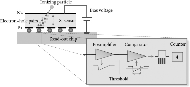
FIGURE 1.3 (See color insert) The schematic illustration of TOT mode. The signal from the electrode is amplified and compared in the comparator. The time the signal is over the comparator level (threshold) represents the energy of the interacting particle. The collected charge is compared in each pixel with the threshold level. If it is lower, the event is not registered and the signal is lost. As a consequence, the charge registered by all pixels is often lower than its original value, which deteriorates the energy resolution.
The TOT mode allows the measurement of the length of time the signal is above the threshold. This time corresponds to the height of the signal; that is, to the charge deposited in the pixel. As was mentioned previously, each pixel has its own analog electronics. Hence, the signal response can differ from pixel to pixel. The signal from an interacting particle can be detected in adjacent pixels. The differences between signals from different pixels results in a systematic error when the signals from several pixels are added together. In order to obtain a response that is as homogenous as possible from all pixels, some calibration procedures have to be carried out.
The energy resolution of the pixelated detector is influenced by the charge-sharing effect [29,30,31,32]. This effect originates from the fact that the charge created by the incoming particle spreads out and is registered between several adjacent pixels (depending on the place of interaction and detector parameters). In single-particle counting detectors such as the Timepix, the charge collected in each pixel is compared with a certain threshold level. If it is lower than this threshold, the event is not registered, the charge is lost, and, as a consequence, the energy resolution of these detectors is deteriorated. Although work has been done to describe the charge-sharing effect in the Timepix detector, and some models for this behavior have been proposed, the direct measurement of the charge-sharing effect is still a tricky issue. Generally speaking, the energy resolution of the Timepix detector cannot currently be compared to dedicated spectroscopic detectors, but it is good enough to obtain very precise measurement of dosimetric values.
As previously discussed, radiation monitors currently used in space are either bulky or are passive detectors. The use of such large hardware is limited. One cannot clip tens or hundreds of kilograms of radiation-monitoring hardware to each spacesuit. Moreover, the price of bringing such massive hardware into orbit is enormous. While passive detectors are lightweight and can be easily attached to a spacesuit or put into any vehicle, they do not provide online information about the radiation field. This drawback is critical. As mentioned before, there are many events in the space radiation environment that cause significant changes in particle fluxes. The fast response and early warning capability of active monitoring hardware provides time-resolved information that is necessary to allow the appropriate reaction of the crews in space. Thus, there is a pressing need for small, compact, low-power, active radiation monitors.

FIGURE 1.4 Photo of an REM. The size of this device is comparable to that of a standard USB flash drive. Moreover, similarly to a flash drive, the REM is plugged in directly to the USB port of the PC or laptop. The REM is controlled by software running on the PC. The analysis of data is also performed in real time by the PC. The entire software suite is stand alone, and it provides the user with dosimetric information about the radiation environment.
The radiation environment monitor (REM) [33] hardware (Figure 1.4) was designed as a demonstration project to show the possibility of creating small, lightweight, low-power radiation monitors using state-of-the-art pixel detectors. The REM is an active monitor connected to a standard PC or laptop via USB. All power and data-transfer requirements are fulfilled through the USB connection. Analysis software running on the PC provides fast and reliable information about the current radiation environment.
The analyzing software was evaluated and fine-tuned during accelerator campaigns prior to the REM hardware launch. A huge set of data, covering a broad range of particle types and energies, was measured with REM and Timepix detectors. Using accelerators has the advantage that the properties of the interacting particles are well known, and this data can serve as a verification and calibration set for current and future analysis algorithms.
Five REMs were delivered to the ISS by Russian Progress 48 in August 2012. They were deployed in October of the same year. From the day of deployment, the detectors have been collecting data, which are analyzed and give real-time information about the radiation environment aboard the ISS (Figure 1.5). Data are also transferred to Earth-based servers on a daily basis. The data are processed again after downlink to create daily, weekly, and monthly reports used by personnel at the National Aeronautics and Space Administration’s Johnson Space Center (NASA JSC).
In summary, the REM hardware has proven to be a viable solution for radiation monitoring aboard the ISS. Following a successful initial deployment of the REM hardware, NASA requested two additional devices to be delivered to the ISS. One unit replaced a REM device, which failed on orbit, while the other will be used to test the advantages of employing a thicker sensor. While previous REM devices employed 300 μm silicon sensors bonded to the Timepix chip, the new unit has a 500 μm sensor. Using a thicker sensor is expected to allow better reconstruction of the angles of incident particles.

FIGURE 1.5 (See color insert) The picture taken aboard the ISS shows the REM deployed on a station support computer. The REM is emphasized in a gray box and shown in detail to the right, plugged into the station laptop.
1.5 ADVANTAGES OF PIXEL DETECTORS
As previously mentioned, the Timepix detectors work like solid-state bubble chambers, wherein each pixel behaves like an independent multichannel analyzer. Thus, properly calibrated detectors [34,35] allow direct measurement of the deposited dose in the sensor. Moreover, additional information about incident particles can be obtained by careful analysis of the tracks that particles create in the sensor. Indeed, for humans it is easy to distinguish different types of particles simply by looking at the track patterns (see Figure 1.6). Image-processing algorithms that analyze tracks created by particle interaction within the sensor are being developed at the University of Houston.

FIGURE 1.6 An example of the radiation background measured for 30 min at the University of Houston (at sea level). One can see the different types of radiation detected in the device just by looking at different patterns created in the sensor. Protons and alpha particles create small round clusters (a). Electron tracks undergo multiple scattering, creating curved tracks (b), while photons create point-like patterns (c).
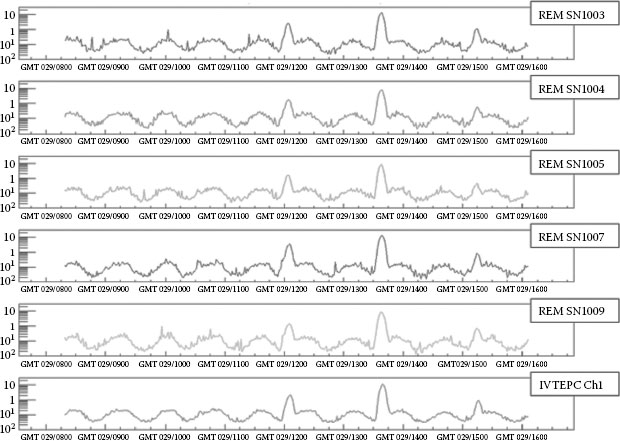
FIGURE 1.7 Comparison of absorbed dose rate measured by five REM devices compared to data obtained by IVTEPC over 8 h. The temporal changes of the radiation environment are clearly visible during the course of the day. It is clearly seen that the trends from all devices are the same. Each device is in a different part of the ISS, and small discrepancies between devices are caused by different shielding around devices.
After more than a year of measurement with REMs aboard the ISS, we can conclude that the REM hardware has exceeded expectations. The data from the REM hardware are carefully compared to other devices on board. The comparison of dose rates measured by REM units and by intravehicular tissue equivalent proportional counters (IVTEPC) is shown in Figure 1.7. It can be seen that, while much smaller, lighter, and less power demanding, the REM devices are capable of providing the same dosimetric data as IVTPEC. Moreover, the extra information obtained by analyzing the tracks of the interacting particles can be utilized to find information such as directionality, particle type, and energy estimation, which up to now were only in the domain of specialized bulky detectors. Over a year operating REM aboard the ISS has shown that pixel detectors can supply all of this information with the use of the appropriate tailor-made algorithms applied to the collected data.
1.6 FUTURE OF RADIATION MONITORS BASED ON PIXEL DETECTORS
Following the success of the REM hardware, NASA initiated two other projects focused on developing new stand-alone radiation monitors based on Timepix technology. One of these devices, the Hybrid Environmental Radiation Assessor (HERA) device, will be the primary radiation monitor for the newly developed Orion module. It is also worth mentioning that other agencies are working on the utilization of pixel-detector technology for dosimetric application. The European Space Agency (ESA) is currently flying a prototype device on the Proba-V satellite, and the Japanese Aerospace Exploration Agency (JAXA) is preparing a device that will be operated on an upcoming satellite (both based on Timepix technology).
But that is not all; progress in microelectronics is so rapid that the Medipix3 collaboration is currently developing a new series of Timepix3 detectors. These devices will provide not only precise spatial and energy information, but also extremely precise (~3 ns) time information in each pixel. Radiation monitors based on such devices would have zero dead time and would obtain the most complete set of information about a particle that can be obtained by one detector.
Bringing these new technologies to the radiation-monitoring field is indeed very exciting. New ideas and approaches can be realized, while some strategies regarding radiation monitoring may be completely altered. One thing is certain; as we stated in the beginning of this chapter, radiation will follow humankind on its journey to the stars. It is up to us to learn how to evaluate and protect ourselves from it.
We would like to express our gratitude to the Medipix2 collaboration and especially to the Institute of Experimental and Applied Physics for delivering the REM hardware and software. We would also like to thank the Space Radiation Analysis Group (SRAG) of NASA JSC for their support.
1. L. S. Pinsky, W. Z. Osborne, J. V. Bailey, R. E. Benson, and L. F. Thompson. Light flashes observed by astronauts on Apollo 11 through Apollo 17. Science 183(4128), 957–959 (1974).
2. R. Paschke, R. W. H. Chang, and D. Young. Probable role of gamma-irradiation in the origin of life. Science 125, 881 (1957).
3. N. B. Cook. The Effects of Atomic Weapons. U.S. Department of Defense (1950).
4. National Council on Radiation Protection and Measurements. Guidance on radiation received in space activities (NCRP Report No.98). NCRP: Bethesda, MD (1989).
5. J. Linsley. Evidence for a primary cosmic-ray particle with energy 1020 eV. Phys. Rev. Lett. 10, 146–148 (1963).
6. R. A. Meyers. Encyclopedia of Physical Science and Technology (3rd edn.), pp. 253–268. Academic Press: San Diego, CA (2003).
7. G. D. Badhwar and P. M. O’Neill. An improved model of galactic cosmic radiation for space exploration missions. Int. J Rad. Appl. Instrum. D. Nucl. Tracks Radiat. Meas. 20(3), 403–410 (1992).
8. G. D. Badhwar and P. M. O’Neill. Galactic cosmic radiation model and its applications. Adv. Space Res. 17(2), 7–17 (1996).
9. P. M. O’Neill. Badhwar–O’Neill 2010 galactic cosmic ray flux model: Revised. IEEE Trans. Nucl. Sci. 57(6), 3148–3153 (2010).
10. NASA Technology Roadmaps. NASA Space Technology Roadmaps and Priorities: Restoring NASA’s Technological Edge and Paving the Way for a New Era in Space. National Research Council of the National Academies: Washington, DC (2012).
11. W. Heinrich, S. Roesler, and H. Schraube. Physics of cosmic radiation fields. Radiat. Prot. Dosimetry 86(4), 253–258 (1999).
12. S. Bourdarie and M. Xapsos. The near-Earth space radiation environment. IEEE Trans. Nucl. Sci. 55(4), 1810–1832 (2008).
13. J. A. Van Allen and L. A. Frank. Radiation around the earth to a radial distance of 107,400 km. Nature. 183(4659), 430–434 (1959).
14. T. I. Gombosi. Physics of the Space Environment (Cambridge Atmospheric and Space Science Series). Cambridge University Press: Cambridge (1998).
15. T. F. Tascione. Introduction to the Space Environment (Orbit: A Foundation Series). Krieger (2010).
16. L. W. Townsend. Implications of the space radiation environment for human exploration in deep space. Radiat. Prot. Dosimetry 115(1–4), 44–50 (2005).
17. S. Biswas and C. E. Fichtel. Nuclear composition and rigidity spectra of solar cosmic rays. Astrophys. J. 139, 941 (1964).
18. M. A. Shea and D. F. Smart. A summary of major solar proton events. Sol Phys. 127(2), 297–320 (1990).
19. J. R. Letaw, R. Silberberg, and C. H. Tsao. Radiation hazards on space missions outside the magnetosphere. Adv. Space Res. 9(10), 285–291 (1989).
20. J. A. Simpson. Elemental and isotopic composition of the galactic cosmic rays. Annu. Rev. Nucl. Par. Sci. 33(1), 323–382 (1983).
21. F. A. Cucinotta, S. Hu, N. A. Schwadron, K. Kozarev, L. W. Townsend, and M. H. Y. Kim. Space radiation risk limits and Earth-Moon-Mars environmental models. Space Weather 8(12) (2010).
22. G. F. Knoll. Radiation Detection and Measurement. Wiley (2011).
23. A. F. McKinlay. Thermoluminescence Dosimetry (Medical Physics Handbooks 5). Heyden & Son: Philadelphia (1981).
24. J. E. Turner. Atoms, Radiation, and Radiation Protection. Wiley: New York (2007).
25. W. S. Boyle and G. E. Smith. Charge coupled semiconductor devices. Bell Syst. Tech. J. 49(4), 587–593 (1970).
26. X. Llopart, R. Ballabriga, M. Campbell, L. Tlustos, and W. Wong. Timepix, a 65k programmable pixel readout chip for arrival time, energy and/or photon counting measurements. Nucl. Instr. Methods A 581, 485–494 (2007).
27. J. Žemlička, J. Jakůbek, M. Kroupa, and V. Tichy. Energy and position sensitive pixel detector Timepix for X-ray fluorescence imaging. Nucl. Instrum. Methods A 607(1), 202–204 (2009).
28. J. Žemlička, J. Jakůbek, M. Kroupa, D. Hradil, J. Hradilová, and H. Mislerová. Analysis of painted arts by energy sensitive radiographic techniques with the pixel detector Timepix. J. Instrum. 6(1) (2011).
29. J. Jakůbek, A. Cejnarová, T. Holý, S. Pospíšil, J. Uher, and Z. Vykydal. Pixel detectors for imaging with heavy charged particles. Nucl. Instrum. Methods A 591(1), 155–158 (2008).
30. J. Jakůbek. Energy sensitive x-ray radiography and charge sharing effect in pixelated detector. Nucl. Instrum. Methods A 607(1), 192–195 (2009).
31. J. Bouchami, A. Gutierrez, A. Houdayer, J. Idarraga, J. Jakůbek, C. Lebel, C. Leroy, J. Martin, M. Platkevič, and S. Pospíšil. Study of the charge sharing in silicon pixel detector with heavy ionizing particles interacting with a Medipix2 device. Nucl. Instrum. Methods A 607(1), 196–198 (2009).
32. J. Marchal. Theoretical analysis of the effect of charge-sharing on the detective quantum efficiency of single-photon counting segmented silicon detectors. J. Instrum. 5, P01004 (2010).
33. D. Turecek, L. Pinsky, J. Jakubek, Z. Vykydal, N. Stoffle, and S. Pospisil. Small dosimeter based on Timepix device for International Space Station. J. Instrum. 6, C12037 (2011).
34. M. Kroupa, J. Jakůbek, and F. Krejčí. Charge collection characterization with semiconductor pixel detector Timepix. IEEE NSS/MIC/RTSD Conf. Proc. R12-37 (2008).
35. J. Jakůbek. Precise energy calibration of pixel detector working in time-over-threshold mode. Nucl. Instrum. Methods A 633(Suppl. 1), S262–S266 (2011).
* Nevertheless, astronauts do see “light flashes” during their time in orbit or in space. Some have reported associated directional components as well. This phenomenon has been known since the time of the Apollo mission [1]. However, it is caused by high-energy particles crossing the eye and its surroundings. If you would like to have the same experience here on Earth, your eye would have to be irradiated by some heavy ion accelerator.
* Omitting pileups. It can be shown that because of the rather short time necessary for signal shaping and small pixel size, modern single-quantum counting devices can operate in very high fluxes without pileups producing significant errors.