
1.1 MARKET FOR MEDIUM- AND HIGH-POWER CONVERTERS
Power electronic converters have been one of the fastest-growing market sectors in the electronics industry over the last 40 years [1]. Power electronic devices are at the heart of many modern industrial and consumer applications and account for $18 billion per year in direct sales, with an estimated $570 billion through sales of other products that include power electronic modules.
The main application areas for power electronics are in power quality and protection, switch-mode power conversion, batteries, and portable power sources, automotive electronics, solar energy technology, communications power, and motion control (classification similar to a Darnell Group market report). The technology behind most products within these markets is on the saturation side of the performance’s S-curve. The industry’s efforts are concentrated in optimization of production and cost efficiency. The Organization of Electronics Manufacturers (OEM) has shown a clear trend for the power supply sector to stay away from custom-designed products and to optimize the standard, modified standard, and modular configurable products.
In power electronics, technology has developed under the pressure of the industry’s needs, and there are many excellent papers written both by industry and university peers over more than 30 years. In synchronous with the technology status, current academic efforts target organization of information, book and tutorial writing, as well as improving the educational means. Moreover, there are new emerging regions of the world, and an ever-increasing number of new students in engineering in new places. This moves the focus of large corporations from achieving the technological leadership toward global market supremacy by production volume, diversity, and global and regional coverage.
Such an impressive count of sources of information may be overwhelming. However, each publication has its own goals, from basic student education textbooks, to industrial design handbooks, or niche tutorials. It is the intention of the present book to understand current technology within a business perspective and to present the existing engineering hands-on knowledge in an organized manner. This book focuses on medium- and high-power converters and the main applications at this power level are
• High-voltage DC transmission lines
• Locomotives
• Ship propulsion
• Large- or medium-sized uninterruptible power supply (UPS) systems
• Motor control from horsepower range to multi-MVA
• Propulsion of electric or hybrid vehicles
• Servo-drives, robot, or welding machine systems
• Elevator systems
• Distributed generation for renewable energy sources
• Appliances, air conditioners, refrigerators, microwave ovens, and washing machines
• Automobile electronics, power steering, power windows, doors, or seats
• Switch-mode power supply for industrial applications
• Consumer electronics, power supplies for VCR, TV sets, and radio
• Distribution systems for computers
Since the book deals with intimate details of designing and working with power electronic converters at medium- and high-power levels, without too much details at the application level, this introductory chapter briefly discusses the most attractive and emerging applications.
The introduction to the first edition has insisted on a series of market realities and numbers since the beginning of the twenty-first century which quest for technological leadership corporations still have. Such commitment for technological performance has generally favored a mathematical approach, a competition based on quantities explicitly shown both in market and technological achievements. Currently, we are witnessing a shift from the interest for quantitative expression of success toward the interest in global coverage and image. The newest financial annual reports of many corporations are less rich in numeric data and more informative on the geopolitical plans of the corporation. Sensitive to this trend, the introduction of the current edition of this book will review more the major technological achievements and less the market numerical data.
The most advanced efforts in power electronics are covering the following activities:
• Semiconductors
• Application development and assimilation of SiC/GaN devices
• New generations of power ICs, taking advantage of new IC technology platforms
• Low-power converters
• Digital power supplies, especially those used for server/computer applications
− Processor power controller with Intel VR10/11, or AMD VID support
− Digital power supply with communication, and variable voltage controller, multiple operation modes
− Generate and/or meet new standards, at the cross-disciplinary field between power supplies and servers/computers
• Lower-voltage output, for newer generations of processors (like 100 A at 1 V)
• Lower-voltage input for energy harvesting devices such as thermo-electric generators
• Conventional low-voltage applications
• Improved power density and efficiency (sustaining efforts at system level, including thermal management)
• Use of new materials in passive components (magnetics and capacitors), with redesign at the converter level to accommodate their peculiar performance
• Generate and/or meet standards derived from the saturation of performance
• Application development
− Light systems, including multiple LEDs
− Energy management in automotive systems, with networks of multiple motor drives
• Given the existing production lines operating at high volume, we have efforts in reliability and protection—models, calculations, physics of failure
• Medium-voltage converters
• Improved power density and efficiency (sustaining efforts at system level, including thermal management)
• New topologies and afferent control for better use of energy while taking advantage of the existing saturation limits of performance if sustaining would not do it, need to cross fields—you need to be really good to see it at the system level
• Application development
− Smart grid, including communications along the transmission of energy, for better energy management
− New products, for energy metering, sensing, production, storage, and transfer
− New algorithms for software calculation of various performance indices
− Application development and assimilation of power converter technology (motor drives) within HVAC and refrigeration systems (fairly new product applications)
− This may require novel and appropriate control algorithms
− Integration of renewable energy sources
− Photovoltaics
− Wind, sun, and water—this topic slowly moves into sustaining mode
• Given the existing production lines operating at high volume, we have efforts in reliability and protection—models, calculations, and physics of failure
• High-voltage converters
• Introduction/design of new power semiconductor devices
• More power electronic control of energy, including active filters, STATCOM devices, power quality controllers, and so on
• Inventive protection devices for high-voltage environment
• Brand new applications in experimental physics and medical equipment
• HV pulse power, plasma science, and scanning microscope systems
• Laser diode, LED, or other projection lamps
1.1.2 TRANSPORTATION ELECTRIFICATION SYSTEMS
The most important current application for power electronic systems lies within the electrification of the transportation systems.
With a continuously evolving market and a continuous demand for new vehicles, the automotive sector embraces more and more electronic-based features. They range from entertainment systems to propulsion systems. This market is expected to double its growth rate in the coming years (from 2005 to 2015). A study [2] states an annual growth rate of 15.5% for the automotive sector, that is the strongest growth market.
These are new divisions for the power electronics market, but they must develop quickly due to the increased demand for efficiency, comfort, and safety. Another study has counted about 80 small-power drives, including two modern cars, in a middle-class American family’s household. The power electronic products used in home applications are designed for low voltage and low power. Low-power servo-drives are described in this book.
Propulsion systems for advanced electric and hybrid vehicles are another emerging application field, with numerous electric and hybrid vehicles already released on the market.
The contemporary efforts are targeting
• Extended energy storage capabilities
• Fast and contactless chargers
• Advanced control algorithms
• Improved reliability to sustain the lifetime expectancy in the automotive products
• New designs for permanent magnet motors
Another transportation-related effort is related to the More Electric Aircraft concept [3,4]. The large aircraft systems feature electrical power systems in the range of 1 MW. The power installed within the electrical power systems is increasing with the introduction of more and more power electronics processing to replace the conventional hydraulic systems. Such a large power needs to be processed by power electronics systems with advantages such as “power on demand,” increased efficiency, small form factor, and so on.
Several modules are well-known examples of success stories:
• Integrated drive generator
• Variable speed constant frequency converter driven by engine
• Auxiliary power unit (115 V, 400 Hz)
• Emergency power source driven by the Ram Air Turbine (RAT system)
• High-voltage DC (HVDC) power systems and conversion to low voltage
• Flight control actuation, brake systems, and doors
• Air conditioning and heating systems
Challenges are related to harmonics, reduction of electromagnetic inference (EMI), and increasing power density. All of these fuel an impressive contemporary R&D effort for More Electric Aircraft based on power electronics concepts.
An emerging application for medium-voltage motor drives consists of rail propulsion systems in the multi-MW range [5–6]. Coming a long way from the beginning of the twentieth century, four major railway power supply systems are the most extended nowadays:
• DC 1.5 kV (6.5% of market in 2003 [5])
• DC 3 kV (30.3% in 2003 [5])
• AC 50 Hz, 25 kV (44.8% in 2003 [5])
• AC 16.7 Hz, 15 kV (13.6% in 2003 [5])
Additionally, subway systems mostly use DC 600–800 V.
The development, especially in Europe and Japan, of power electronics used in locomotive propulsion has encouraged replacement of gate turn-off thyristors (GTOs) switches by their modern insular gate bipolar transistor (IGBT) counterparts. Traditional GTO solutions [6] were in use since early 1990 s, in the 6.4 MW EuroSprinter locomotive built by Krauss-Maffei and Siemens. Other examples are the locomotives RENFE8252 in Spain and CPLE5600 in Portugal. Other important corporations playing a role in railway electrification are Alstom, Bombardier Transportation (which absorbed the former ABB/ADTranz), or new comers such as the Swiss’ Stadler Rail in cooperation with ABB.
Contemporary R&D efforts target:
• Power electronics for high-speed trains
• Expansion of onboard energy storage
• New concepts in permanent magnet synchronous motors
• Electronic transformer, especially for the 16.7 Hz applications
• Improvements in flux-orientated control algorithms
• Optimization of system level issues for the transmission and distribution of energy
The ship marine power systems represent contemporary effort for market success. Over the last 5 years (2008–2013), numerous large corporations, or small business endeavors have released an impressive number of new devices and systems to this sector.
Electric propulsion has redeemed itself as the proper choice for large cruise ships and is already accepted more and more for warships. Unfortunately, simple operating profiles of some low-power vessels or commercial pressures make the all-electric solution not generally attractive. There exist many types of ships between these two extremes in which an all-electric solution can be successful. This solution provides potential for safer, more flexible, and sustainable vessels in the future as well as increased effectiveness in war and reduced life-cycle cost within the warship fleet.
In the past, the U.S. Navy acquired and implemented all-electric ship-propulsion systems for warships and submarines. Since the late 1990s, Eaton NCD (currently DRS Technologies) has already delivered a 2.2 MW brushless DC motor drive for submarine propulsion [7], and such efforts are continuing within the defense industry around the world.
Current efforts are mainly targeting expansion to smaller vessels, offering more and more electrical equipment for propulsion, services, auxiliary power, and navigation for either military, commercial, or entertainment vessels. Integration of small renewable energy sources, improved onboard energy storage, power management, and actuator supply are trying to cope up with the ever-increasing power demand.
1.1.3 TRADITIONAL INDUSTRIAL APPLICATIONS
Despite the decreasing number of production facilities and the reduction of new facility development, the industrial sector is still asking for motor drives. The market share for the motor drives has developed steadily during the last 40 years [1,10,11,12]. This market opportunity has been followed with a strong R&D effort leading to a continuous technology development. However, advanced knowledge has allowed complete automation of the production lines, which has soon led to excess capacity and which, in turn, has resulted in a decrease in the revenue growth rate from 16.6% in 1970 to 5.5% in 2000 [8]. The resulting price erosion has been overcome by introducing new semiconductor devices and improving control algorithms and motor designs to reduce the cost, improve the efficiency, and increase the applicability to a large number of uses. Moreover, the motor drive market has in time a larger share of the nonindustrial products’ market, in contrast to the trends of the last 20 year, when the end-market has been industrial. Home appliance power electronics and motor drives are good examples in this sense.
1.1.3.2 Grid-Tied Power Supplies
Another large business profile for electronic power converters is the UPS or grid-related applications. In 2001, the total worldwide market for UPS alone was at $5.3 billion. A derivative from this market is distributed generation, which is probably (since 2002) the most dynamic R&D sector in power electronics in the United States. The combination of a grid power supply and a nonconventional power source such as a diesel generator, a fuel-cell, or a wind turbine requires power electronics conditioning and protection. The appropriate power converters do not really bring anything new in their structure or packaging, but their control is a challenge yet to be solved.
Other related consumer markets include the AC/DC power supply, the PC and work-station power supply markets, and the communication power market. As these markets use only low-voltage systems, they are therefore not the direct focus of this book. However, these emergently ask for more power within the distribution system that is controlled with electronics.
Another new market segment deals with medium-voltage motor drives, in the range of 3300 V and 2000 A. High-voltage IGBTs have been introduced recently, and they take more and more the role of the GTOs. The complete picture here is filled with new devices, such as the integrated gate commutated thyristor (IGCT), a traditional IGBT device with the gate driver colocated with the power semiconductor. Motor drives delivering 19,000 HP are nowadays built by companies such as Siemens Corporation.
Different solutions for multilevel inverters are of interest for medium- and high-voltage applications allowing operation of up to 25 kV. A special approach consists of a stack of connected single-phase inverters, which is being extensively analyzed in the ABB and Daimler laboratories.
Harmonic performance is limited, however, due to limited switching frequency. New device materials such as silicon-carbide (SiC) may make the dream of high-frequency switching come true for medium- or high-voltage applications.
The biggest difference from the other fields of electronics is the power coordinate. If students learn about a circuit or method for any other class of applications of electronics, they can easily manage to debug or put into service versions of that circuit from different manufacturers or within different applications. Power electronic circuits and their applications, however, are very different. The topology of a three-phase rectifier equipped with thyristors can be used for a 500 MVA HVDC transmission line or for a 1 kW welding machine. We can understand the basic operation of the three-phase phase-controlled rectifier from a college textbook, but the two systems are extremely different in reality. Each thyristor circuit explained in the textbook has a different implementation in practice, ranging from a half-inch T0–220 package to a building of six floors. The protection circuits are also very different, and range from no protection at all to sets of computer-controlled panels and automatic hot-swap replacement units. Finally, the cooling system could range from environmental air to complex systems of pumps or fans that by themselves have large installed power, often controlled with variable frequency through power electronics equipment.
Given this diversity of power levels and applications, different power semiconductor switches are more suitable for each case. Figure 1.1 stretches over the whole range of possible switching frequencies and installed power achievable with a single device. For larger power levels, multiple converters can be hardware connected in parallel. Modern power semiconductor devices, especially those of high power, require a good knowledge and control of their dv/dt and di/dt variations. These can be achieved through gate control as well as through circuit design, as shown in Chapter 2, which is dedicated to understanding the operation and parameters of diverse power semiconductor devices.
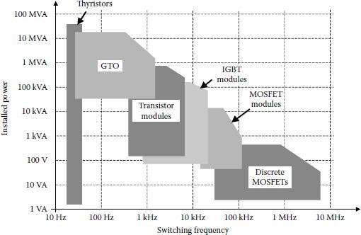
FIGURE 1.1 Power switches availability.
The core of any power electronic converter is the control algorithm, and multiple options for pulse width modulation (PWM) algorithms are detailed in the book. The implementation possibilities for these control methods are shown from a historical perspective to allow the reader to understand that the semiconductor technology embedded in microcontrollers influence continuously the way we think about the PWM algorithms.
Each class of converters is dedicated a separate chapter, including topologies that are in demand by industry as well as topologies that lost somewhat their appeal while they still offer a huge academic and educational benefit.
The final chapter presents advanced concepts considered by the author as possible to find success in certain niche applications where conventional products still leave room for improvement with advanced concepts.
A three-phase adjustable speed drive (ASD) comprises not just the power converter; it is a whole system that includes the power converter.
Figure 1.2 shows a complete ASD system consisting of:
• A three-phase rectifier system able to convert the grid three-phase system into a DC voltage
• An intermediate DC circuit usually composed of a large capacitor bank
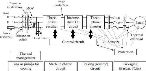
FIGURE 1.2 Global view on a three-phase ASD system.
• A three-phase inverter able to generate variable frequency, and variable voltage in the three-phase system
• A control circuit built with a digital signal processor (DSP), microcontroller, or programmable logic circuit (PLC) device
• Sensors and analog-signal preprocessing
• Connect/disconnect power switches, fuses, or protection circuitry
• Thermal-management system based on heatsinks or coldplates and a cooling system
• Start-up circuit with charging of the DC bus capacitor
• Braking resistor circuit
The input stage, called the three-phase rectifier, is built in many applications with rectifier diodes. The DC bus voltage is therefore quasi-constant at 1.35 times the line-to-line voltage (VLL). For a system with a VLL of 460 V, the DC voltage equals 620 V. Rarely, this power converter is made with silicon-controlled rectifier (SCR) devices in order to control the DC voltage with a method called phase control. Both solutions introduce very large harmonics of the current on the grid. These can become bothersome at large power levels, pollute the grid, and create problems for other users.
Another solution used often during the last few years consists of active front-end rectifiers built with controllable devices such as IGBTs or MOSFETs. Such three-phase power converters can process power directly, or they can be used as active filters to deliver the difference between the square-wave current produced by the diode rectifier and an ideal sinusoidal waveform. Thus, they result rated at a lower power level. If a direct three-phase active converter is used, the DC bus voltage can be higher due to the boost operation of that converter. This is advantageous, as it is easier to manipulate high-power levels from a high-voltage source.
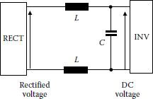
FIGURE 1.3 Intermediate DC circuit.
The intermediate circuit is also called the DC Link, as it really is a DC link between the input rectifier and the output inverter. It serves as a power storage device. It is composed of a reactor inductor and a capacitor bank. Inductors filter the current through the capacitor in order to limit losses and heating. These two components are the bulkiest parts in the converter system panel (Figure 1.3).
Many manufacturers of ASD use a very large capacitance on the bus in order to ensure a power ride by enabling the motor to continue to operate when grid power is interrupted. Because of this large capacitance, however, it takes a longer time for these capacitors to discharge once power is turned off.
The main functions of the DC capacitor bank are to
• Filter the harmonic ripple produced by the switching devices to produce clean sine-in, sine-out waveforms.
• Provide a stable voltage to ensure the control system’s stability.
• Store energy useful for quick transients in the output.
• Work together with the brake resistor to limit DC voltage during regeneration of the “inverter” power stage.
• Limit overvoltages (clamp) before the system protection takes over and shutdown the power devices or start other auxiliary protection.
If the load is unbalanced or nonlinear, an alternative current circulates through the DC bus at twice the fundamental frequency. Depending on the value of the DC capacitor, this current can produce an oscillation of the DC bus voltage. Additional capacitive kVA in the DC link seems mandatory for inverters that feed unbalanced or nonlinear loads. This implies:
• Increased weight, volume, cost
• Selection of DC link to satisfy the maximum expected imbalance or worstcase nonlinear
• Increased losses and reduced reliability of the DC link components
Different active filtering solutions are considered to solve this problem.
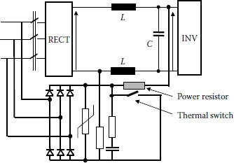
FIGURE 1.4 Principle of a soft-charge circuit.
ASDs at power levels above 30 HP (22.5 kW) use a soft-charge circuit for powering up the drive. Without this circuit, the in-rush current will be very large at power-on due to the extremely small impedance of the discharged DC bus capacitor. This large in-rush current would blow the grid fuses if not damage the rectifier semiconductors.
Figure 1.4 presents a possible soft-charge circuit. It basically adds a power resistor in the path of capacitor charging. This power resistor is also protected with a thermal switch able to disconnect above a certain temperature. After the voltage on the capacitor is larger than a minimum value, the power converter is disconnected through the grid disconnect switch. Due to the cooling requirements for the power resistor, the ASD can start only after 1 or 2 min.
The other important part of the intermediate circuit consists of the DC reactor. This is also called choke or DC coils. It has two basic functions:
• Reduce the harmonics of the current by about 40%, with advantages in the power source or grid current.
• Help reduce power interruptions to avoid numerous nuisance shut-downs.
The intermediate circuit may also contain a brake circuit that takes the power from the DC bus when the drive is decelerating or stopping (Figure 1.5). Its operation is very simple: when the voltage across the capacitor bank increases above a certain level, the IGBT is turned-on and the power resistor is connected across the DC bus, at the inverter input. The inverter current now feeds a parallel R–C circuit. A large part of this current circulates through the resistor along with the discharge current from the capacitor. Usually, the brake circuit is part of the ASD, and the brake resistor is something the user adds depending on his requirements for a specific application.
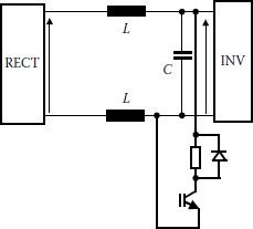
FIGURE 1.5 Brake circuit.
One alternative to using the brake circuit is to transfer the excess power back to the grid through a power converter. This is called regeneration due to its efficiency advantages. However, one drawback is that it produces harmonics on the grid voltage affecting the incoming power to the converter. Finally, another option is to transfer the power excess to another drive’s DC bus capacitor. This is sometimes called load sharing.
The third major component of the system is the three-phase inverter. This is used for conversion of energy from DC voltage in an AC three-phase system with variable frequency and variable voltage. Typically, the topology is based on six IGBTs connected in a bridge; this will be discussed later in Chapter 3. Control of the three-phase inverter for this purpose is called pulse width modulation (PWM). Different PWM methods will be introduced in Chapters 4 and 5. Other topologies for DC/AC conversion are also presented in this book in Chapters 6 and 7.
A very important function for the whole ASD system is represented by the protection circuitry. We have protection for each power semiconductor device at over-voltage, over-current, over-temperature, or at problems within the gate drivers. The appropriate protection circuits will be presented in Chapter 3. More protection at the system level includes input or output fuses.
Voltage on the DC bus and of the output currents is monitored through sensors. Some manufacturers use two current sensors at the output of the inverter while others use three sensors, one for each phase.
Large-power ASDs include motor coils that allow the operation of the motor far from the ASD system. For instance, the standard distance for a Danfoss drive is up to 300 m (1000 ft) for unshielded (unscreened) cable and 150 m (500 ft) for shielded (screened) cable [9]. If these coils are not used, the standard distance from the drive to the motor is as low as 50 m (160 ft) [9].
All of these blocks are supervised, monitored, and controlled from a central controller module. This is usually implemented on a digital circuit built around a micro-controller, DSP, PLC, or field programmable gate array (FPGA), application-specific integrated circuits (ASIC).
There are several functions that mandatorily must be included in the system:
• System command
• System initialization
• Run auto-test program
• Define start/stop functions and check their operation
• Define acceleration/deceleration of the system
• Define sense of rotation or direction of displacement
• Interfaces
− Display data
− User-interface
− Communication with upper hierarchical level
• Control and regulation
• Control algorithm
• Data acquisition and digital processing
• Regulation
• Limits of control variables
• Nonlinear characteristics
• Rectifier control when it is not built with only diodes
• Synchronization
• Command angle generation
• Harmonic control
• Power factor control
• Gate control
• Inverter control
• Three-phase system generation
• PWM generation
• Minimum pulse control
• Change of voltage and frequency
• Limit of the operation range
• Supervision
• Protection
• Diagnosis
• Data storage
• Report to upper level through communication interface
Chapters 6 and 7 will provide details about the experimental aspects of implementing these functions in modern microcontrollers.
Power converters used for ASD applications generally need to satisfy some requirements or standards. Typical requirements are next presented.
1.4 GRID INTERFACES OR DISTRIBUTED GENERATION
Power electronics has been used for controlling and monitoring power transfer through HVDC links, especially in countries such as Canada and Brazil with isolated or local power systems. The back-to-back connection of controlled rectifier bridges on both ends of a DC transmission line allows control of up to 150 MW after the AC/DC/AC conversion [10]. However, these systems are rather rare, and the extensive use of power electronics in power systems is increasing as either active filters or grid interfaces. Many utility companies are providing solutions for power quality at the facility level on the utility side of the power meter. This multi-MW equipment is expensive and not likely to find success in the market.
A separate class of applications deals with nonconventional power sources, such as fuel cells, solar power, micro-turbines, or wind power. These projects with distributed energy sources manage local power generation in the range of 1 kW to 1 MW. For instance, one of the largest fuel-cell-based equipment is installed in Anchorage, Alaska, and accounts for 1 MW [11,12].
Special features are included in power converter controls in order to transfer energy from any of these energy sources or conventional batteries to grid [13]. At higher-power levels, this energy is exchanged on three-phase systems. Two operation modes are typical for these applications:
• Grid parallel: power converters that synchronize with the grid while exchanging energy from or to the grid.
• Stand-alone: that maintains three-phase voltage generation while the grid is disconnected.
Definitely, the control system must be able to switch between these modes any time the grid is lost or re-appears suddenly. Such requirements are also present in a conventional UPS system. The distributed generation system can also combine power delivery from the grid and the alternate source of energy.
The power electronic system maintains many of the protection and connection features presented for the ASD case. Let us take a closer look at the requirements of the grid interface.
The switching nature of operating power converters has led to various concerns about the quality of the grid at the point where the power converter is connected. Many standards have been elaborated in this respect. Some of these follow general requirements for inverters, some are specific for the grid connection. Any new power electronic equipment dedicated to a grid interface must obey regulations. Unfortunately, there are different grid voltage systems in the world, and grid requirements are different from country to country. Constraints to low-voltage grid applications around the world are presented next. Appropriate standards are next quoted, and they can be consulted for larger grid voltage systems:
• Nominal voltage ratings and operating tolerances for 60 Hz electric power systems from 100 V through 230 kV [14]
• Voltage sags analysis and methods of reporting sag characteristic graphically and statistically [15]
• Guidelines and limits for current and voltage distortion levels on transmission and distribution circuits [16]
• Powering and grounding sensitive electronic equipment [17]
• Monitoring of single-phase and polyphase AC power systems [18]
• Incompatibility of modern electronic equipment with a normal power system [19]
• Distributed resources interconnected with electric power systems [20]
Most European countries require compliance with EN61000-3-2. It lays down absolute limits for each individual harmonics. Japan’s regulations are also derived from EN61000-3-2. Australia, the United States, and the United Kingdom set relative limits with a Total Harmonic Distortion (THD) of the current of 5% maximum and maximum values for each individual harmonic. Methods for minimizing those grid harmonics are presented in Chapter 9.
Power converters are also subject to harmonics from grid. The harmonics of the mains (grid) voltage a converter can cope with are given in the European standard EN60146-1-1 [13,14].
A power factor of 1.00 is considered the best case, while anything higher than 0.8 is acceptable. If these levels cannot be achieved with the power system itself, additional units are used for power factor correction. This is the case of large inductive loads on the grid or on silicon-controlled rectifiers.
The high-frequency components of the input currents can be further reduced with chokes on the mains or on the DC link. DC link chokes also prevent resonance with the grid impedance. The incorporation of DC chokes on the power converter structure reduces the harmonic currents by up to 40% [13,14].
It is very important not to inject DC components on the grid. Many countries avoid transformerless connection of switching converters to the grid. The operation of the power-switching converter must be symmetrical, so as not to produce DC components. The amount of DC current accepted by different countries is very different. A maximum of 0.5 mA is allowed in the United Kingdom; Australia’s regulations allow a maximum of 0.5% of the power converter’s rated current or 5 mA, whichever is greater; the U.S. regulations limit DC to a maximum of 0.5% of rated current; Japan allows a maximum 1% of rated current; and Germany a maximum 1 A per power converter connected to grid [13,14].
1.4.4 ELECTROMAGNETIC COMPATIBILITY AND ELECTROMAGNETIC INFERENCE
Step-switching waveforms of up to 15 V/ns or 5 A/ns generate EMI in both conducted and radiated forms. The conducted EMI is generated in differential (symmetrical) mode or common (asymmetrical) mode. Symmetrical mode EMI is generated when currents flow into the connection lines due to the power semiconductor variation of current (di/dt). The common mode EMI is produced due to the high (dv/dt) and parasitic capacitances to ground or connecting lines.
The radio or EMI interference produced by power converters depends on a number of factors:
• Switching frequency of the converter
• Slope of current and voltage at switching
• Impedance of the mains power supply
• Length of cables from grid and to the motor
Standards have been defined for previous applications of power converters, and they are re-applied to these grid interfaces. The most used standards for EMI are the German standard VDE or the Europe standard EN55011 (Figure 1.6). Appliances are covered by Europe standard EN55014, while power converter products are covered by EN61800-3.
The interference conducted to grid is usually reduced with a filter composed of coils and capacitors. If the power converter is not built with this filter, it can be purchased separately: “class A” for industrial applications and “class B” for household applications. Moreover, using screened or armored cables limits the interference generated from power converter to the switching motor.
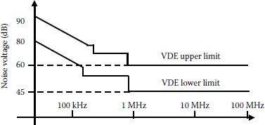
FIGURE 1.6 Example of EMI standard requirements.
A new trend in EMI protection is the use of converter methods to reduce the common mode voltages; this will be analyzed in detail in Chapter 6.
1.4.5 FREQUENCY AND VOLTAGE VARIATIONS
It is accepted that power converters connected to grid can operate only within certain voltage and frequency windows. The system is considered stable within these windows. Along with voltage or frequency limits, a maximum allowable run-on time is also defined, and it varies considerably from country to country. Table 1.1 shows these limits [20].
1.4.6 MAXIMUM POWER CONNECTED AT LOW-VOLTAGE GRID
The maximum power installed in a power converter used as a grid interface is not always regulated by standards. Single-phase converters can be connected to low-voltage systems if their power is below 4.6 kW in Germany or Austria, 5 kW in the United Kingdom or Italy, and 10 kW in Australia. Three-phase converters can be connected to a low-voltage grid if their power is below 25 kW in Mexico, 30 kW in Australia, and 100 kW in Portugal. Obviously, higher-power converters can be connected to three-phase systems with higher voltages.
TABLE 1.1
Voltage and Frequency Variations
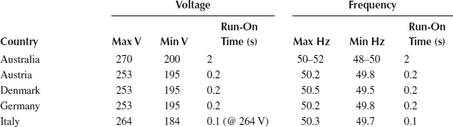
Source: Data compiled from Panhuber, C. 2001. PV System Installation and Grid Interconnection Guidelines in Selected IEA countries, Raport IEA-PVPS, T5, April.
1.5 MULTICONVERTER POWER ELECTRONIC SYSTEMS
The advent of power electronic applications in industry changed the focus from issues related to building the power converter to issues related to system development and interaction between different power converters. Many modern industrial systems are composed of several ASDs connected to the same DC bus in multidrive or multi-module configurations. Modular design in multiconverter applications is based on the knowledge gained by individual analysis of each power converter. Power quality, efficiency, and system stability are affected by the interdependency between power stages.
Examples of multiconverter applications are:
• Industrial multidrive systems
• Parallel operation achieving higher-power levels
• Electric or hybrid electric vehicles
• Aircraft power electronic systems
• Ship power electronic systems
• Space electronic systems
Figure 1.7 shows a schematic of a modern power electronic system. The power source can be the industrial AC grid followed by an AC/DC power conversion, or the main power source can be a nonconventional power source, such as solar, wind, or thermal energy. After the appropriate conversion, the whole power resides on the DC bus. This bus supplies several motor drives. Some of them can dynamically be on the motoring mode, some on regeneration. The important thing is to manage the power on the DC bus so that the voltage is kept within two certain limits. This raises new problems, such as the stability of the DC bus at different loads. If one of the ASDs is working at constant torque with its speed regulated, its power can be considered constant. A load with constant power presents negative dynamic impedance that is a source of instability on the bus. Chapter 9 makes an extensive analysis of multiconverter power electronic systems.
Multidrive or multiconverter systems have several advantages:
• Modularity: quick and easy to integrate in panels and cabinets
• Scalability
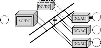
FIGURE 1.7 Complex power electronics system comprised of several drives.
• Redundancy
• Reliability: easy to replace a faulty module with a new one (hot-swap possible)
• Electronic gearing
• Flexibility: modules can be customized to any application
• Use of the same control cards and software for a large number of applications
• The same personnel training requirements across a wide power range
• Reduced-size library of AutoCad drawings, easy to integrate in a new design
• Lead-time reduction and money savings by minimizing spare requirements
• Same packaging and power density across the whole power range
• Technical advantages of using a single, high-power DC bus structure
• Optimized cooling system
Power electronics has emerged as a well-established technology with a broad range of applications. This chapter has shown the application range for medium and high-power converters, and it has focused on ASDs and grid interfaces. Constraints and standards to be met by different power converters within these applications are briefly listed. Equipment involving power converters are being increasingly used in all domains of our lives. Most of this energy is processed at medium and high power through power converters. The following chapters take an in-depth look at the theory of three-phase power converters, giving details of their problems and providing many solutions that can be implemented.
1. Neacsu, D. 2005. Business plan for R&D operations in power electronics, Graduation Project, Tufts University, Gordon Institute, April 26, Scientific Advisers: Professors Arthur Winston and Mary Viola.
2. Anon, 2006. Market and Technology Study Automotive Power Electronics 2015, Arthur D. Little White Paper.
3. Wheeler, P. 2009. The more electric aircraft why aerospace needs power electronics, European Power Electronics and Applications Conference, EPE’09, pp.1–30.
4. Said, W. 2011. Aircraft electric power system—A power conversion perspective, IEEE Power and Energy Magazine, August.
5. Steimel, A. 2010. Power-electronics issues of modern electric railway systems, 10th International Conference on Development and Application Systems, Suceava, Romania, pp. 1–6.
6. Bochetti, G., Bordignon, P., Perna, M., and Venanzo, P. 1993. 3MW converter for high power universal locomotive based on deionized water cooled GTO module—Improvements and type tests, Proceeding of 5th European Power Electronics Conf. (EPE’93), Brighton, UK, 1993, pp. 241–246.
7. Divan, D. and Brumsickle, W.E. 1999. Powering the next millennium with power electronics, Proceedings of the IEEE 1999 International Conference on Power Electronics and Drive Systems IEEE PEDS, 7–17, Hong Kong, 1999, pp. 7–10 vol. 1.
8. Anon, 2001. Electronic motor drive market projected to top $19 billion by 2005. Appliance Design Magazine (www.appliancedesign.com), August 14, 2001.
9. Drives 101, Danfoss lessons, Danfoss Internet Documentation, www.danfoss.com.
10. Baker, M.H. and Bruges, R.P. 1991. Design and experience of a back-back HVDC link in western Canada, in Proceedings of the IEE Conference on Advances in Power Systems Control Operation and Management, Hong Kong, pp. 686–693.
11. Gilbert, S. 2001. The nation’s largest fuel cell project: A 1 MW fuel cell power plant deployed as a distributed generation resource, Project Dedication August 9, 2000, IEEE Rural Electric Power Conference, Anchorage, Alaska, 2001, pp. A4/1–A8/1.
12. Bartos, F.J. and Gulalo, G. 1998. Power modules and devices advance motor controls. Control Eng. J., 45(6), 91–101.
13. IEEE P1547 Std Draft 10 Standard for Distributed Resources Interconnected with Electric Power Systems, 2003.
14. ANSI C84.1–1989 American National Standards for Electric Power Systems and Equipment Ratings (60 Hertz).
15. IEEE Std 493–1900 IEEE Recommended Practice for Design of Reliable Industrial and Commercial Power Systems (IEEE Gold Book).
16. IEEE Std 519–1992 IEEE Recommended Practice and Requirements for Harmonic Control in Electric Power Systems, 1992.
17. IEEE Std 1100–1992 IEEE Recommended Practice for Powering and Grounding Sensitive Electronic Equipment (IEEE Emerald Book), 1992.
18. IEEE Std 1159–1995 IEEE Recommended Practice for Monitoring Electric Power Quality, 1995.
19. IEEE Std 1250–1995 IEEE Guide for Service to Equipment Sensitive to Momentary Voltage Disturbances, 1995.
20. Panhuber, C. 2001. PV System Installation and Grid Interconnection Guidelines in Selected IEA countries, Raport IEA-PVPS, T5, April.