
Chapter Twelve. Tolerancing
Objectives
After studying the material in this chapter, you should be able to:
1. Describe the nominal size, tolerance, limits, and allowance of two mating parts.
2. Identify a clearance fit, interference fit, and transition fit.
3. Describe the basic hole and basic shaft systems.
4. Dimension mating parts using limit dimensions, unilateral tolerances, and bilateral tolerances.
5. Describe the classes of fit and give examples of each.
6. Draw geometric tolerancing symbols.
7. Specify geometric tolerances.
8. Relate datum surfaces to degrees of freedom.
Refer to the following standards
• ANSI/ASME Y14.5 Dimensioning and Tolerancing
• ANSI B4.1 Preferred Limits and Fits for Cylindrical Parts
• ANSI B4.2 Preferred Metric Limits and Fits
• ASME Y14.43 Dimensioning and Tolerancing Principles for Gages and Fixtures
• ISO 5459 Geometrical Product Specifications
• ISO 286-1; ISO 286-2
• ISO 1101

Specifying Tolerance Is Essential to Ensuring that Interchangeable Parts Fit Together in Assemblies. A worker makes notes on a new John Deere engine at a factory in Pune, Maharashtra, India. (Courtesy of JOERG BOETHLING/Peter Arnold, Inc.)
Understanding Tolerance
Tolerancing is an extension of dimensioning. It allows you to specify a range of accuracy for the shape, size, and position of every feature of a product, so that the manufactured parts will fit together and function properly when assembled. CAD software often provide features for dimensioning, tolerancing, and checking fits and interferences that aid in the tolerancing process. To effectively provide tolerances in your drawings and CAD models, you must:
• Understand the fit required between mating parts.
• Have a clear picture of how inspection measurements are performed.
• Be able to apply tolerance symbols to a drawing or model.
• Apply functional tolerancing to individual part features.
Tolerance
Tolerance is the total amount a specific dimension is permitted to vary. Tolerances are specified so that any two mating parts will fit together. To keep part cost low, specify a tolerance as large as possible that still permits satisfactory function of the part. Tolerance can be stated several different ways on a drawing.
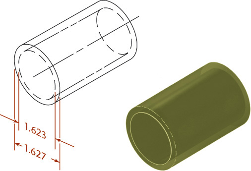
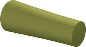
One method of providing a tolerance is to specify the dimension and give a plus or minus range after it. Figure 12.1 shows an example of a bilateral tolerance. A dimension given as 1.625 ± 0.002 means that the manufactured part may be 1.627 or 1.623 or anywhere between these maximum and minimum limit dimensions, as shown in Figure 12.2. The tolerance (the total amount the actual part feature is allowed to vary from what is specified) is 0.004.

Quality Control
When you purchase parts or have them manufactured by another company, you must have a way to ensure that the parts are manufactured precisely enough.
Before paying for parts, most companies have a process to quality certify (QC) the parts against the drawing or model. Larger batches of parts may use statistical methods in which a relevant sample of the parts are inspected instead of all the parts. Some companies require certification from the part vendor rather than inspecting parts themselves.
A tolerance must be specified for each dimension so that it can be determined how accurately the part must be manufactured to be acceptable. The tolerances that you specify are based on the part’s function and fit.
Definitions for Size Designation
You should become familiar with the size designation terms that apply in tolerancing.
Feature A physical portion of a part, such as a pin, or a hole, or the representation of such a feature on a drawing or in a model.
Feature of size The two types of features of size are regular and irregular. A regular feature of size is a cylindrical or spherical surface, a circular element (such as the cross section of a cylinder), or a set of two opposed parallel elements or opposed parallel surfaces that are associated with a directly toleranced dimension.
Actual local feature The measured value of any individual cross section of a feature of size.
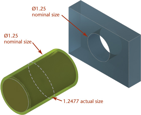
Nominal size is used for general identification and is usually expressed in decimals or, less often, common fractions. In Figure 12.3, the nominal size of both hole and shaft, which is 1.25″, would be 1-1/4″ or 31.75 mm.
Allowance is the minimum clearance space (or maximum interference) that is specified to achieve a fit between two mating parts. In Figure 12.3, the allowance is the difference between the size of the smallest hole and the size of the largest shaft. Allowance represents the tightest permissible fit. For clearance fits this difference will be positive, but for interference fits it will be negative.
Variations in Form
The dimensions of the cylinder in Figure 12.1 specify a bilateral tolerance that allows the part to be +.002 or –.002 from the 1.625 dimension specified. The drawing or model specifies the cylinder’s shape, and the dimensions and tolerance specify its size and the allowable variation that the size may have.
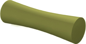
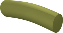
But what about imperfections of the form? Some imperfections of form that may occur in manufacturing cylinders are shown in Figures 12.4–12.7. Of course, they are greatly exaggerated in the illustration. Because nothing can be made to exact perfection, some of these types of variations will occur in manufacturing. The objective of providing a tolerance is to indicate the acceptable amount of variation so that the parts will still fit and function.
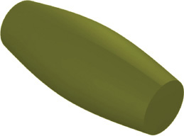
You can think of tolerance as defining a perfect form envelope that the real produced part must fit inside in order to be acceptable.
Tip
You can sometimes notice variations in form by placing a machinists’ scale along the edge of the part and checking to see whether you can slip a feeler gage between the scale and the edge of the part.
Tolerance Envelope
The following terms describe the tolerance envelope:
Actual mating envelope The envelope toward the outside of the material, in which the acceptable actual feature must fit. For external parts, like cylinders, this is the perfect feature at the largest permissible size; for internal features, like holes, this is the perfect feature at the smallest permissible size.
Actual minimum material envelope This envelope is the counterpart to the actual mating envelope. For an acceptable external feature, it is the perfect feature at the smallest permissible size; for an internal feature this is the perfect feature at the largest permissible size.
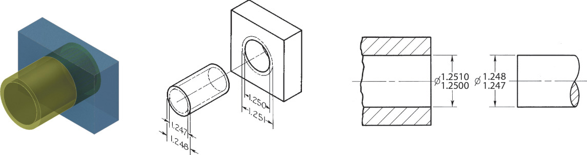
Figure 12.8a illustrates the idea of a part fitting inside the perfect form envelope. The part (a shaft) is represented in green and the actual mating envelope and actual minimum material envelope are shown as blue areas. The part can be any size that is no larger than the actual mating envelope and no smaller than the actual minimum material envelope.

12.8 (a) Acceptable Fit. (b) Section Showing Fit. (c) Unacceptable Part (extends beyond the actual mating envelope). (d) Unacceptable Part (extends beyond the actual minimum material envelope). (Variations are exaggerated for the purpose of illustration.)
Figure 12.8c illustrates a bowed part that extends outside the actual mating envelope. Figure 12.8d shows a waisted part that extends beyond the actual minimum material envelope.
Implied Right Angles
When lines or centerlines intersect on a drawing at angles of 90°, it is customary not to dimension the angle. This situation is called an implied 90° angle. If the angle is something other than 90°, it must be dimensioned to be understood clearly.
Implied 90° angles have the same general tolerances applied to them as do any other angles covered by a general note. The exception is when a geometric tolerance is used for that feature. When geometric tolerances are specified, implied 90° or 0° angles between feature centerlines are considered basic dimensions to which no tolerance applies outside that stated by the geometric tolerance. Figure 12.9 shows a simple dimensioned drawing with a general tolerance note. The tolerance of plus or minus 1° applies to the implied 90° angles as well as to the dimensioned angles in the drawing. Figure 12.10 shows a drawing where implied 90° angles are controlled by the tolerance noted in the title block. Later in this chapter you will learn to use geometric dimensioning and tolerancing to control angles with greater precision.

12.9 Noted tolerances apply to implied 90° angles the same as they do to dimensioned angles that are not noted otherwise.
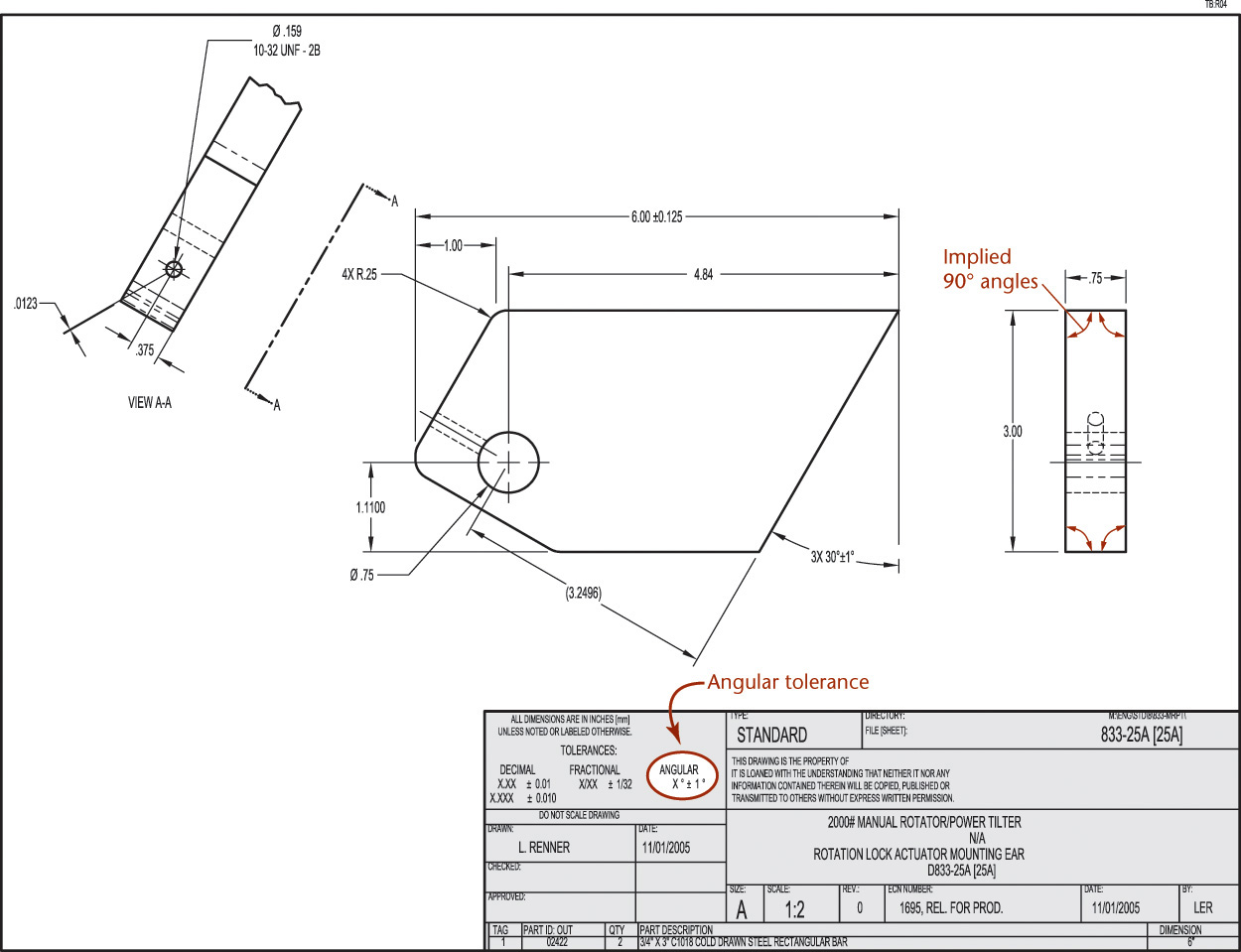
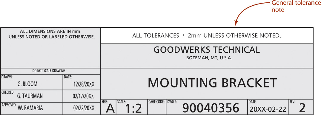
12.10 Tolerance block note is applied to implied 90° angles in the drawing. (Courtesy of Wood’s Power-Grip Co., Inc.)
Fits between Mating Parts
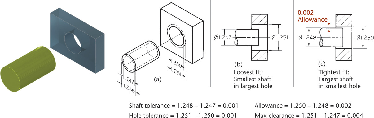
Fit is the range of tightness or looseness resulting from the allowances and tolerances in mating parts. The loosest fit, or maximum clearance, occurs when the smallest internal part (shaft) is in the largest external part (hole), as shown in Figure 12.11a. The tightest fit, or minimum clearance, occurs when the largest shaft is in the smallest hole, as shown in Figure 12.11b. The difference between the largest allowable shaft size and the smallest allowable hole size (0.002″ in this case) is the allowance. There are three general types of fits between parts.

Clearance Fit A clearance fit occurs when an internal part fits into an external part with space (or clearance) between the parts. In Figure 12.12, the largest shaft is 1.248″ and the smallest hole is 1.250″, giving a minimum space (allowance) of .002″ between the parts. In a clearance fit, the allowance is always positive.
Interference Fit An interference fit occurs when the internal part is larger than the external part, so the parts must be forced together. In Figure 12.13, the smallest shaft is 1.2513″ and the largest hole is 1.2506″, so the interference of metal between parts is at least .0007″. For the largest shaft and smallest hole, the interference is 0.0019″. In an interference fit, the allowance is always negative.
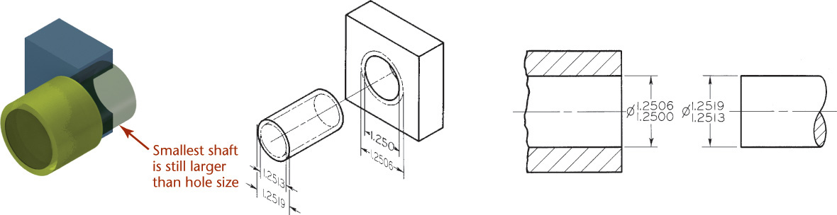
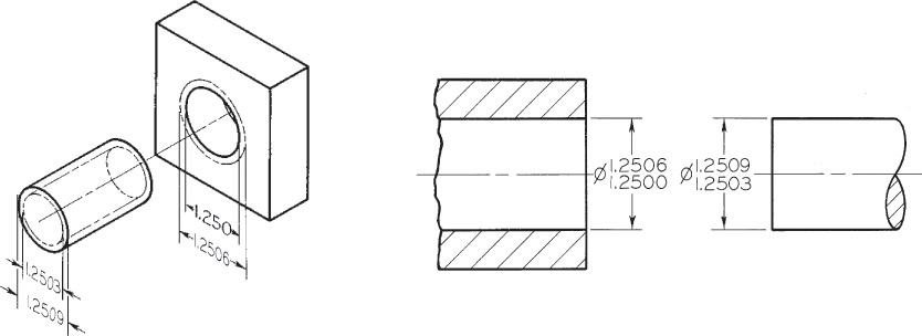
Transition Fit A transition fit refers to either a tight clearance or interference. In Figure 12.14 the smallest shaft, 1.2503″, will fit into the largest hole, 1.2506″. But the largest shaft, 1.2509″, will have to be forced into the smallest hole, 1.2500″.
Line fit is sometimes used to indicate limits that are specified so that a clearance or surface contact results when mating parts are assembled.
Specifying Fit Using Limit Dimensions
Limit dimensions are a method of directly specifying tolerance by providing dimensions for the upper and lower limits of the feature’s size. The high limit (maximum value) is placed above the low limit (minimum value) in place of the dimension value.
In the example shown in Figure 12.15, the actual hole may not be less than 1.250″ and not more than 1.251″. These are the limits for the dimension, and the difference between them (.001″) is the tolerance, as is indicated in Figure 12.16a. Likewise, the shaft must be between limits 1.248″ and 1.247″. The difference between these limits is .001″ so the tolerance for the shaft is .001″. The minimum clearance is .002″, so any shaft will fit inside any hole interchangeably.
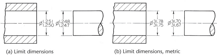
In metric dimensions, the limits for the hole are 31.75 mm and 31.78 mm. Their difference, 0.03 mm, is the tolerance (Figure 12.16b). Similarly, the limits for the shaft are 31.70 mm and 31.67 mm, and the difference between them, the tolerance, is 0.03 mm.
When parts are required to fit properly in assembly but are not required to be interchangeable, they are not always toleranced, but it is indicated on the drawing that they are to be made to fit at assembly. Figure 12.17 shows an example of this type of note.

Selective Assembly
If allowances and tolerances are specified properly, mating parts are completely interchangeable, but for close fits, it is necessary to specify very small allowances and tolerances. The cost of manufacturing parts to such precision may be very high.
To avoid this expense, either manual or computer-controlled selective assembly is often used. In selective assembly, all parts are inspected and classified into several grades according to actual sizes, so that “small” shafts can be matched with “small” holes, “medium” shafts with “medium” holes, and so on. Figure 12.18 shows variation among the sizes of mating parts at an exaggerated size to illustrate the general idea.
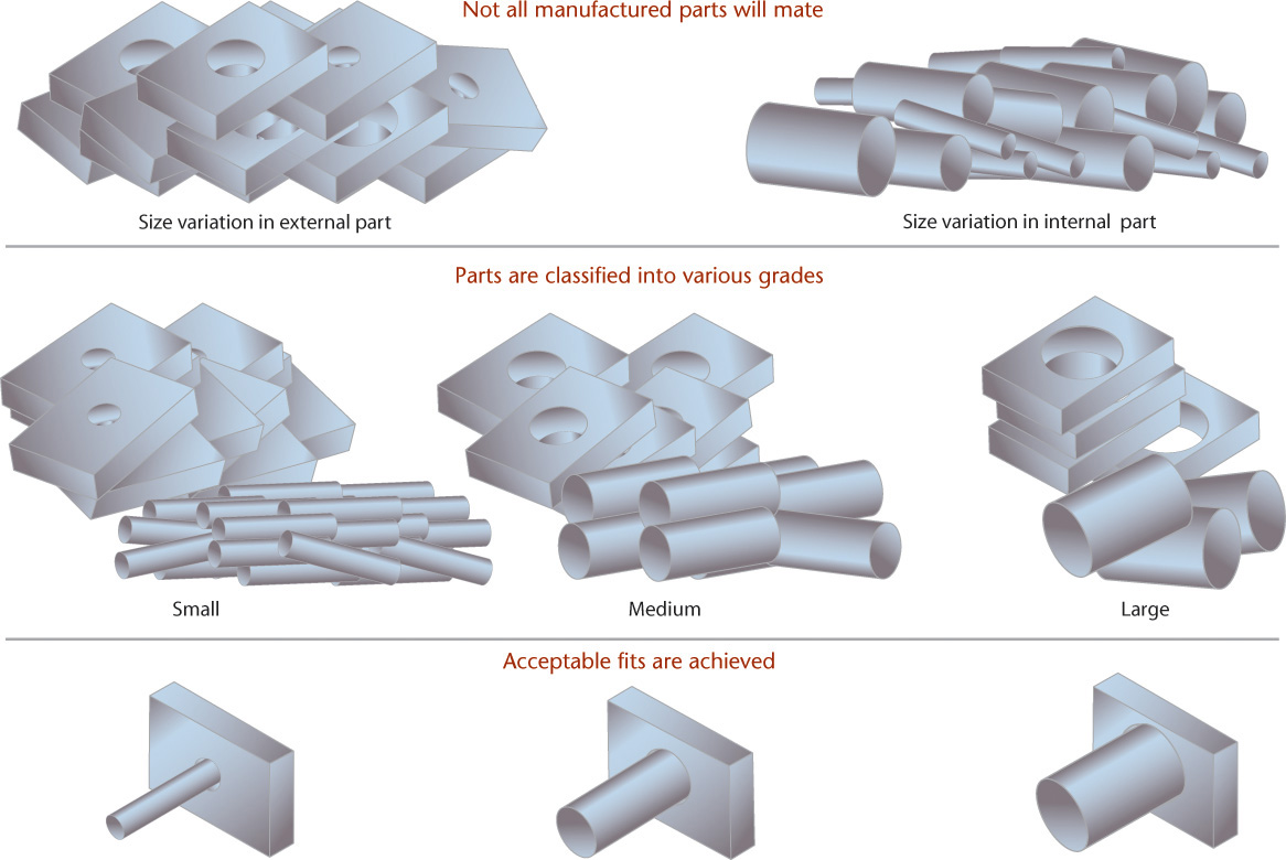
12.18 Selective Assembly (Difference between the sizes of mating parts is exaggerated for visibility.)
Using selective assembly, acceptable fits may be obtained at less expense than by machining all mating parts to highly accurate dimensions. This method is often effective when using transition fits, since either clearance or interference is allowed. The use of selective assembly makes ordering replacement parts difficult.
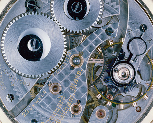
The inner workings of a watch are an example of parts that must fit precisely to work. (Courtesy of Philip Harvey/SuperStock.)
Hole System
Reamers, broaches, and other standard tools are often used to produce holes, and standard plug gages are used to check the actual sizes. In contrast, shafts are easily machined down to any size desired. Therefore, toleranced dimensions are commonly determined using the hole system, in which the minimum hole is taken as the feature size for the design. Then, the allowance is determined, and tolerances are applied. Figure 12.19 shows a CAD model where several shafts assemble into different holes. Figure 12.20 shows the fit between two parts sized based on the hole diameter.
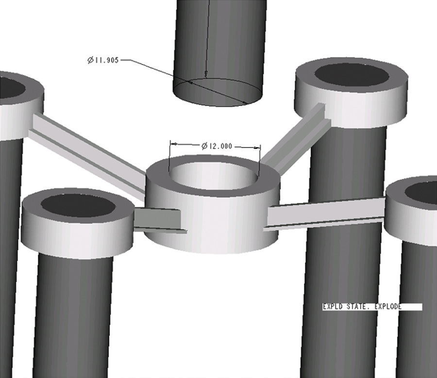
12.19 Tolerances are usually based on the hole size, because holes are usually formed using standard tool sizes.
Shaft System
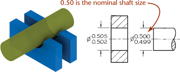
In some industries, such as textile machinery manufacturing, which use a great deal of cold-finished shafting, the shaft system is used. It is advantageous when several parts having different fits are required on a single shaft, as in Figure 12.21, or when the shaft for some reason can’t be machined to size easily. This system should be used only when there is a reason for it. In this system, the maximum shaft is taken as the feature size for the design and an allowance for each mating part is assigned, then tolerances are applied.
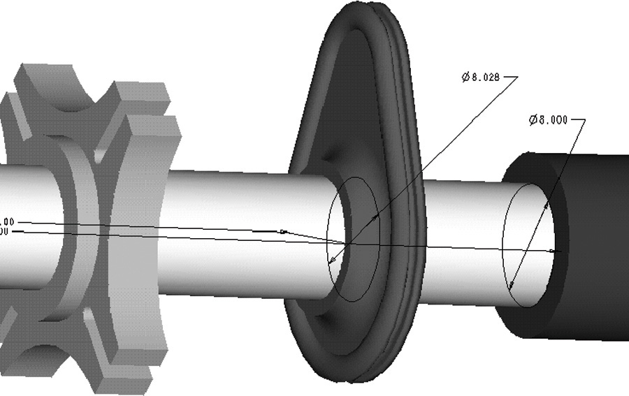
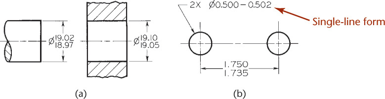
In Figure 12.22, the maximum size of the shaft, .500″, is the feature size for the design. For a clearance fit, an allowance of .002″ is decided on, giving the minimum hole size of .502″. Tolerances of .003″ and .001″, respectively, are applied to the hole and the shaft to obtain the maximum hole, .505″, and the minimum shaft, .499″. The minimum clearance is the difference between the smallest hole and the largest shaft, and the maximum clearance is the difference between the largest hole and the smallest shaft.
In the case of an interference fit, the minimum hole size is found by subtracting the desired allowance from the nominal shaft size.
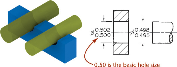
Step by Step: Using the Hole System
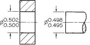
![]() Determine where mating parts fit. Because the hole will be machined with a standard-size tool, its size will be used to determine the fit. In the figure shown, the minimum size of the hole, .500″, is used.
Determine where mating parts fit. Because the hole will be machined with a standard-size tool, its size will be used to determine the fit. In the figure shown, the minimum size of the hole, .500″, is used.
![]() Determine the type of fit and apply the allowance. For a clearance fit, an allowance of .002″ is subtracted from the hole size, making the maximum shaft size .498″, because it is easier to machine the shaft down to a smaller size than to apply the allowance to the hole.
Determine the type of fit and apply the allowance. For a clearance fit, an allowance of .002″ is subtracted from the hole size, making the maximum shaft size .498″, because it is easier to machine the shaft down to a smaller size than to apply the allowance to the hole.
Clearance Fit
![]() Apply the tolerance. Tolerances of .002″ and .003″, in this example, are applied to the hole and the shaft, respectively, to obtain the maximum hole of .502″ and the minimum shaft of .495″. Thus, the minimum clearance is the difference between the smallest hole and the largest shaft, .002, and the maximum clearance is the difference between the largest hole and the smallest shaft, .007.
Apply the tolerance. Tolerances of .002″ and .003″, in this example, are applied to the hole and the shaft, respectively, to obtain the maximum hole of .502″ and the minimum shaft of .495″. Thus, the minimum clearance is the difference between the smallest hole and the largest shaft, .002, and the maximum clearance is the difference between the largest hole and the smallest shaft, .007.
Interference Fit

In the case of an interference fit, find the maximum shaft size by adding the desired allowance (the maximum interference) to the hole size.
In the figure at left, the hole size is 1.2500″. The maximum interference decided on was .0019″, which when added to the hole size gives 1.2519″ as the largest shaft size.
Manufacturing to One Millionth of an Inch
Gage blocks, used for inspection and calibration, must be manufactured to extremely precise tolerances.
Gage blocks, also known as “Jo blocks” are made from steel, chrome, or ceramic and lapped and honed to accuracies of even just a few millionths of an inch (0.0000254 mm). These precise blocks are used in calibration and inspection. They are often used with a sine bar to measure angles precisely. Using the equation
sin angle = height/distance,
the fixed distance of the sine bar, and setting the precise height by raising one end of the sine bar on a gage block or stack of gage blocks, you can find precise angles. When the angle is known, the height of the gage blocks can be calculated from the equation. Often, tables are used to look up the needed height quickly to produce the required angle for setting up a machine.
Gage blocks are finished so precisely (flatness of around 1 microinch) that they “ring” when slowly slid together and aligned. These blocks are not magnetic. There is some debate as to the exact combination of air pressure, surface tension from the light film of oil or water vapor on the gage blocks, and/or the interchange of electrons between atoms of the surfaces of the two blocks that creates an attractive molecular force that holds the blocks together.
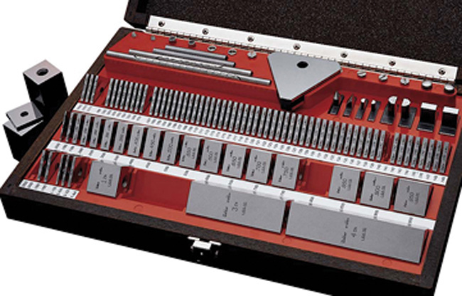
Set of Starrett-Weber Gage Blocks (Courtesy of L.S. Starrett Company.)
12.1 Specifying Tolerances
Every dimension on a drawing should have a tolerance, either direct or by a tolerance note. The primary ways to indicate tolerances in a drawing are
• A general tolerance note listed in a note or a table;
• A note providing a tolerance for a specific dimension;
• A reference on the drawing to another document that specifies the required tolerances;
• Adding limit tolerances to dimensions;
• Adding direct plus/minus tolerances to dimensions; and
• Geometric tolerances.
Many of these tolerancing methods can be used in combination in the same drawing.
12.2 General Tolerance Notes
General notes are usually located in the lower right corner of the drawing sheet near the title block. Often, general tolerance notes are included in the title block itself. For example, a general tolerance note might state,
ALL TOLERANCES ±1 mm
UNLESS OTHERWISE NOTED.
ANGLES ±1 DEGREE.
This indicates that for a dimension value written as 25, for example, any measurement between 24 and 26 on the actual part would be acceptable.
Many companies have standard title blocks they insert into CAD drawing files containing general tolerancing standards for the type of production that is common to their industry. Figure 12.23 shows an example of a general tolerance note.
Another way general tolerances are stated is with a table on or near the title block indicating the tolerance by the number of digits used in the dimension, as shown in Figure 12.24. For example:


This type of table indicates that single-place decimal dimensions have a tolerance of ±.2. For example, a dimension value written as 3.5 could range anywhere from 3.3 to 3.7 on the actual part and still be acceptable. A dimension written as 3.55 could range from 3.53 to 3.57 on the actual part. And a value written as 3.558 could range from 3.557 to 3.559 and be acceptable. It is uncommon to see more than three decimal places listed for inch drawings, because precisions of ±.0001 are very high precision manufacturing and would be unlikely to be indicated merely by a general tolerance note.
12.3 Limit Tolerances
Limit tolerances state the upper and lower limits for the dimension range in place of the dimension values, as shown in Figure 12.25. Figure 12.26 shows examples of limit tolerances in a drawing. The upper value is always placed above the lower value. In single-line note form, the low limit precedes the high limit, and the two values are separated by a dash, for example, 29–32.

Single-Limit Dimensioning
It is not always necessary to specify both limits when you use a single-limit tolerance. The note MIN or MAX is placed after a number to indicate the minimum or maximum dimension desired when other elements of design determine the other unspecified limit. For example, a thread length may be dimensioned as 1.500 MIN FULL THD or a radius dimensioned as R .05 MAX. Other applications of single-limit dimensions include depths of holes and chamfers.
12.4 Plus-or-Minus Tolerances
In this method the basic size is followed by a plus-or-minus expression for the tolerance (Figure 12.27). The result can be:
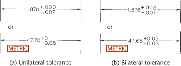
• Unilateral when the tolerance applies in only one direction so that one value is zero; or
• Bilateral when either the same or different values are added and subtracted.
If two unequal tolerance numbers are given—one plus and one minus—the plus value is placed above the minus. One of the numbers may be zero. If the plus value and minus value are the same, a single value is given, preceded by the plus-or-minus symbol (±), as shown in Figure 12.28.

The unilateral system of tolerances allows variations in only one direction from the nominal size. This method is advantageous when a critical size is approached as material is removed during manufacture, as in the case of close-fitting holes and shafts. In Figure 12.27a, the nominal size is 1.878″ (47.70 mm). The tolerance of .002″ (0.05 mm) is all in one direction—toward the smaller size. If the dimension is for a shaft diameter, the nominal size of 1.878″ (47.70 mm) is nearer the critical size, so the tolerance is subtracted from the critical size. A unilateral tolerance is always all plus or all minus, but the zeros for the other tolerance value should be shown as in Figure 12.27a.
The bilateral system of tolerances allows variations in both directions from the nominal. Bilateral tolerances are usually given for location dimensions or any dimensions that can be allowed to vary in either direction. In Figure 12.27b, the nominal size is 1.876″ (47.65 mm), and the actual local feature may be larger by .002″ (0.05 mm) or smaller by .001″ (0.03 mm). If equal variation in both directions is allowed, the plus-or-minus symbol is used, as shown in Figure 12.28.

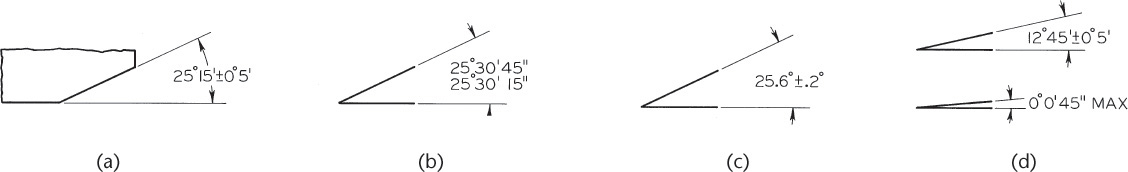
Angular tolerances are usually bilateral and given in terms of degrees, minutes, and seconds (Figure 12.30), unless geometric dimensioning and tolerancing is used. Limit tolerances for angles, as shown in Figure 12.30b, are less commonly used.
12.5 Tolerance Stacking
It is very important to consider the effect of one tolerance on another. When the location of a surface is affected by more than one tolerance value, the tolerances are cumulative. In some cases, for functional reasons, it may be desirable to define dimensions (such as X, Y, and Z shown in Figure 12.31a) chain fashion, without regard to the overall width of the part. This allows the tolerance to accumulate or “stack up.” If the overall width dimension is shown in Figure 12.31a, the part is controlled in too many different ways—it is overdimensioned. In such cases, if it is shown, the overall dimension should be a reference dimension placed inside parentheses to indicate that it is for reference only.
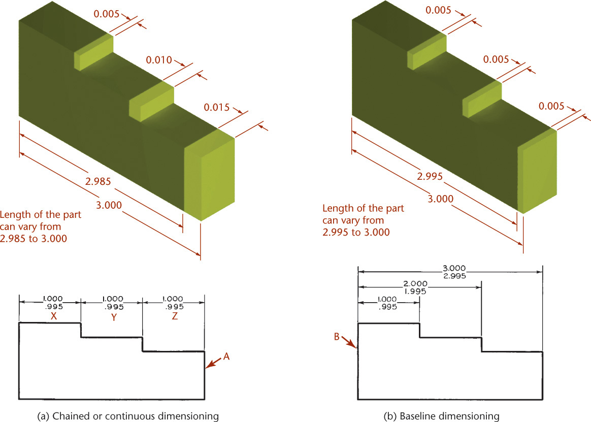
In other cases it may be desired to hold two dimensions (such as X and Y in Figure 12.31a) and the overall width of the part closely by giving the overall width dimension. In that case, a dimension such as Z should be omitted or given as a reference dimension only. As a rule, it is best to dimension each surface so that it is affected by only one dimension. This can be done by referring all dimensions to a single datum surface, such as B shown in Figure 12.31b.
Chained or Continuous Dimensioning
When dimensions are specified as a chain, the tolerances for the part may add up. A chained dimension uses the end of one dimension as the beginning of the next. Tolerance stacking refers to the way the tolerance for one dimension is added to the next dimension in the chain and so on from one feature to the next, resulting in a large variation in the location of the last feature in the chain. Figure 12.31a illustrates this effect where the surface labeled A is dimensioned chain fashion. Consider the location of the right end surface relative to the left end of the part. When features X, Y, and Z are at their maximum size, the surface at the right end of the part can vary within a .015-wide zone. Tolerance stacking is not necessarily bad, if that is the intent for the relative locations of the features. You should be aware of the effect that tolerance has on chained dimensions and specify the tolerances this way only when you want the tolerance to accumulate.
Baseline Dimensioning
Baseline dimensioning locates a series of features from a common base feature. Tolerances do not stack up because dimensions are not based on other toleranced dimensions. Figure 12.31b illustrates how the same part in Figure 12.31a could be dimensioned using baseline dimensioning. Baseline dimensioning can make it easy to inspect the part, because features are measured from a common base feature. Dimensioning from a zero point as the base feature can also be a useful technique for dimensioning parts for NC machining.
12.6 Using American National Standard Limits and Fit Tables
The American National Standards Institute has issued ANSI B4.1, Preferred Limits and Fits for Cylindrical Parts, defining terms and recommending preferred standard sizes, allowances, tolerances, and fits in terms of the decimal inch. This standard gives a series of standard classes of fits on a unilateral-hole basis so that the fit produced by mating parts of a class of fit will produce approximately similar performance throughout the range of sizes. These tables give standard allowances for any given size or type of fit; they also prescribe the standard limits for the mating parts that will produce the fit.
The tables are designed for the hole system (see Appendices 4–8). For coverage of the metric system of tolerances and fits, see Appendices 10–13.
Table 12.1 gives the three general types of fits, the five subtypes, their letter symbols, and descriptions.
Table 12.1 General Fit Types and Subtypes
Fit Type |
Symbol |
Subtype |
Description |
Clearance |
RC |
Running or sliding fits |
Running and sliding fits (Appendix 4) are intended to provide a similar running performance, with suitable lubrication allowance, throughout the range of sizes. The clearances for the first two classes, used chiefly as slide fits, increase more slowly with diameter than the other classes, so that accurate location is maintained even at the expense of free relative motion. |
Locational |
LC |
Clearance fits |
Locational fits (Appendices 5–7) are fits intended to determine only the location of the mating parts; they may provide rigid or accurate location, as with interference fits, or provide some freedom of location, as with clearance fits. Accordingly, they are divided into three groups: clearance fits, transition fits, and interference fits. |
LT |
Transition clearance or interference fits |
||
LN |
Locational |
||
Interference |
FN |
Force or shrink fits |
Force or shrink fits (Appendix 8) constitute a special type of interference fit, normally characterized by the maintenance of constant bore pressures throughout the range of sizes. The interference therefore varies almost directly with diameter, and the difference between its minimum and maximum value is small to maintain the resulting pressures within reasonable limits. |
In the fit tables for each class of fit, the range of nominal sizes of shafts or holes is given in inches. To simplify the tables and reduce the space required to present them, the other values are given in thousandths of an inch as in the example shown in Figure 12.32. Minimum and maximum limits of clearance are given; the top number is the least clearance, or the allowance, and the lower number the maximum clearance, or loosest fit. Then, under the heading “Standard Limits,” are the limits for the hole and for the shaft that are to be applied to the nominal size to obtain the limits of size for the parts, using the hole system.
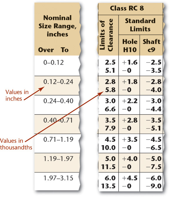
12.32 Portion of RC8 Fit Table. The International Organization for Standardization (ISO) publishes a similar series of fit tables for metric values.

Milling machines can produce parts within tolerances of 0.5 mm, or a few thousandths of an inch. (Courtesy of Ron Sherman/Creative Eye/MIRA.com)
12.7 Tolerances and Machining Processes
Tolerances should be as generous as possible and still permit satisfactory use of the part. The tighter the tolerance, the more expensive it is to manufacture the part. Great savings can be gained from the use of less expensive tools, from lower labor and inspection costs, and from reduced scrapping of material.
Table 12.2 is a chart to be used as a general guide to the tolerances achievable by the indicated machining processes. You can convert these to metric values by multiplying by 25.4 and rounding to one fewer decimal places.
Table 12.2 Tolerances Related to Machining Processes
Range of Sizes (in.) |
Tolerances |
|||||||||
|
To and |
|||||||||
.000 |
.599 |
.00015 |
.0002 |
.0003 |
.0005 |
.0008 |
.0012 |
.002 |
.003 |
.005 |
.600 |
.999 |
.00015 |
.00025 |
.0004 |
.0006 |
.001 |
.0015 |
.0025 |
.004 |
.006 |
1.000 |
1.499 |
.0002 |
.0003 |
.0005 |
.0008 |
.0012 |
.002 |
.003 |
.005 |
.008 |
1.500 |
2.799 |
.00025 |
.0004 |
.0006 |
.001 |
.0015 |
.0025 |
.004 |
.006 |
.010 |
2.800 |
4.499 |
.0003 |
.0005 |
.0008 |
.0012 |
.002 |
.003 |
.005 |
.008 |
.012 |
4.500 |
7.799 |
.0004 |
.0006 |
.001 |
.0015 |
.0025 |
.004 |
.006 |
.010 |
.015 |
7.800 |
13.599 |
.0005 |
.0008 |
.0012 |
.002 |
.003 |
.005 |
.008 |
.012 |
.020 |
13.600 |
20.999 |
.0006 |
.001 |
.0015 |
.0025 |
.004 |
.006 |
.010 |
.015 |
.025 |
Lapping and Honing |
||||||||||
Grinding, Diamond |
||||||||||
Broaching |
|
|||||||||
Reaming |
|
|||||||||
Turning, Boring, |
||||||||||
Milling |
||||||||||
Drilling |
|
12.8 Metric System of Tolerances and Fits
The preceding material on limits and fits between mating parts applies for both systems of measurement. A system of preferred metric limits and fits by the International Organization for Standardization (ISO) is in the ANSI B4.2 standard. The system is specified for holes, cylinders, and shafts, but it is also adaptable to fits between parallel surfaces of such features as keys and slots. The following terms for metric fits, shown in Figure 12.33a, are somewhat similar to those for decimal inch fits:
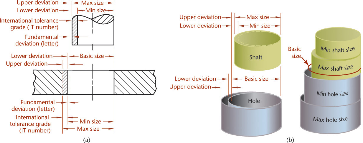
12.33 Terms Related to Metric Limits and Fits (Reprinted from ASME B4.2-1978, by permission of The American Society of Mechanical Engineers. All rights reserved.)
Basic size/nominal size Basic size/nominal size is the size from which limits or deviations are assigned. Basic sizes, usually diameters, should be selected from a table of preferred sizes, as shown in Table 12.3. Figure 12.34 shows examples of preferred and accceptable methods of specifying tolerances on a drawing. Deviation The deviation is the difference between the basic size and the hole or shaft size. This is equivalent to the tolerance in the decimal-inch system.

Upper deviation The upper deviation is the difference between the basic size and the permitted maximum size of the part. This is comparable to the maximum tolerance in the decimal-inch system.
Lower deviation The lower deviation is the difference between the basic size and the minimum permitted size of the part. This is comparable to the minimum tolerance in the decimal-inch system.
Fundamental deviation The fundamental deviation is the deviation closest to the basic size. This is comparable to the minimum allowance in the decimal-inch system.
Tolerance The tolerance is the difference between the permitted minimum and maximum sizes of a part.
International tolerance grade The international tolerance grade (IT) is a set of tolerances according to the basic size that provides a uniform level of accuracy within the grade. For example, in the dimension 50H9 for a close-running fit in Figure 12.34, the IT grade is indicated by the numeral 9. (The letter H indicates that the tolerance is on the hole for the 50 mm dimension.) In all, there are 18 IT grades—IT01, IT0, and IT1 through IT16 (see Figures 12.35 and 12.36 for IT grades related to machining processes and for the practical use of the IT grades).
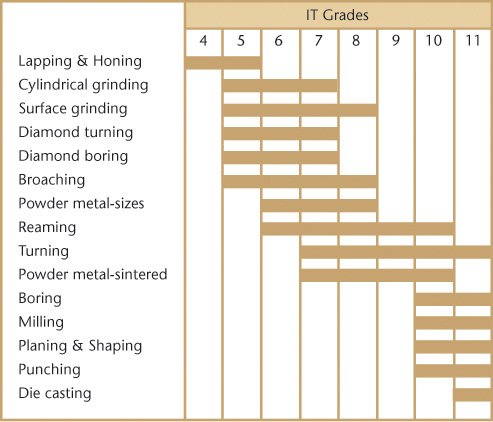
12.35 International Tolerance Grades Related to Machining Processes (Reprinted from ASME B4.2-1978, by permission of The American Society of Mechanical Engineers. All rights reserved.)

Tolerance zone The tolerance zone refers to the relationship of the tolerance to the basic size. It is established by a combination of the fundamental deviation indicated by a letter and the IT grade number. In the dimension 50H8, for the close-running fit, the H8 specifies the tolerance zone, as shown in Figure 12.37.
Hole system The hole system of preferred fits uses the basic diameter as the minimum size. For the generally preferred hole-basis system, shown in Figure 12.37a, the fundamental deviation is specified by the uppercase letter H.
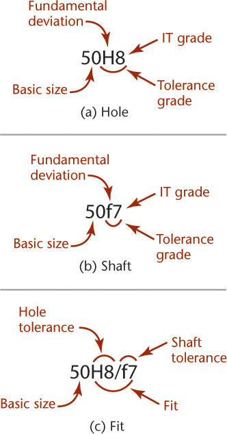
12.37 Applications of Definitions and Symbols to Holes and Shafts (Reprinted from ASME B4.2-1978, by permission of The American Society of Mechanical Engineers. All rights reserved.)
Shaft system The shaft system of preferred fits is a system in which the basic diameter is the maximum size of the shaft. The fundamental deviation is given by the lowercase letter f, as shown in Figure 12.37b.
Interference fit An interference fit results in an interference between two mating parts under all tolerance conditions.
Transition fit A transition fit results in either a clearance or an interference condition between two assembled parts.
Tolerance symbols Tolerance symbols are used to specify the tolerances and fits for mating parts, as shown in Figure 12.37c. For the hole-basis system, the 50 indicates the diameter in millimeters, the capital letter H indicates the fundamental deviation for the hole, and the lowercase letter f indicates the deviation for the shaft. The numbers following the letters indicate the IT grade. Note that the symbols for the hole and shaft are separated by a slash. Tolerance symbols for a 50-mm-diameter hole may be given in several acceptable forms, as shown in Figure 12.38. The values in parentheses are for reference only and may be omitted. For upper and lower limit values, see Appendix 10.

12.38 Acceptable Methods for Stating Tolerances (Reprinted from ASME Y14.5M-1994 (R2004), by permission of The American Society of Mechanical Engineers. All rights reserved.)
12.9 Preferred Sizes
The preferred basic sizes for computing tolerances are given in Table 12.3. Basic diameters should be selected from the “First Choice” column, because these are readily available stock sizes for round, square, and hexagonal products.
Table 12.3 Preferred Sizes (Reprinted from ASME B4.2-1978, by permission of The American Society of Mechanical Engineers. All rights reserved.)
Basic Size, mm |
Basic Size, mm |
Basic Size, mm |
|||
First Choice |
Second Choice |
First Choice |
Second Choice |
First Choice |
Second Choice |
1 |
10 |
100 |
|||
1.1 |
11 |
110 |
|||
1.2 |
12 |
120 |
|||
1.4 |
14 |
140 |
|||
1.6 |
16 |
160 |
|||
1.8 |
18 |
180 |
|||
2 |
20 |
200 |
|||
2.2 |
22 |
220 |
|||
2.5 |
25 |
250 |
|||
2.8 |
28 |
280 |
|||
3 |
30 |
300 |
|||
3.5 |
35 |
350 |
|||
4 |
40 |
400 |
|||
4.5 |
45 |
450 |
|||
5 |
50 |
500 |
|||
5.5 |
55 |
550 |
|||
6 |
60 |
600 |
|||
7 |
70 |
700 |
|||
8 |
80 |
800 |
|||
9 |
90 |
900 |
|||
1000 |
12.10 Preferred Fits
The symbols for either the hole-basis or shaft-basis preferred fits (clearance, transition, and interference) are given in Table 12.4. Fits should be selected from this table for mating parts where possible.
Table 12.4 Preferred Fits (Reprinted from ASME B4.2-1978, by permission of The American Society of Mechanical Engineers. All rights reserved.)
ISO Symbol |
||||
Hole Basis |
Shaft Basis* |
Description |
||
Clearance Fits |
H11/c11 |
C11/h11 |
Loose-running fit for wide commercial tolerances or allowances on external members. |
More Clearance → |
H9/d9 |
D9/h9 |
Free-running fit not for use where accuracy is essential, but good for large temperature variations, high running speeds, or heavy journal pressures. |
||
H8/f7 |
F8/h7 |
Close-running fit for running on accurate machines and for accurate location at moderate speeds and journal pressures. |
||
Transition Fits |
H7/g6 |
G7/h6 |
Sliding fit not intended to run freely, but to move and turn freely and locate accurately. |
|
H7/h6 |
H7/h6 |
Locational clearance fit provides snug fit for locating stationary parts; but can be freely assembled and disassembled. |
||
H7/k6 |
K7/h6 |
Locational transition fit for accurate location, a compromise between clearance and interference. |
← More interference |
|
Interference Fits |
H7/n6 |
N7/h6 |
Locational transition fit for more accurate location where greater interference is permissible. |
|
H7/p6 |
P7/h6 |
Locational interference fit for parts requiring rigidity and alignment with prime accuracy of location but without special bore pressure requirements. |
||
H7/s6 |
S7/h6 |
Medium drive fit for ordinary steel parts or shrink fits on light sections, the tightest fit usable with cast iron. |
||
H7/u6 |
U7/h6 |
Force fit suitable for parts that can be highly stressed or for shrink fits where the heavy pressing forces required are impractical. |
For values corresponding to the fits, see Appendices 10–13. Although second- and third-choice basic-size diameters are possible, they must be calculated from tables not included in this text. For the generally preferred hole-basis system, note that the ISO symbols range from H11/c11 (loose running) to H7/u6 (force fit). For the shaft-basis system, the preferred symbols range from C11/h11 (loose fit) to U7/h6 (force fit).
Suppose that you want to use the symbols to specify the dimensions for a free-running (hole-basis) fit for a proposed diameter of 48 mm. Because 48 mm is not listed as a preferred size in Table 12.3, the design is altered to use the acceptable 50-mm diameter when possible. From the preferred fit descriptions in Table 12.4, the free-running (hole-basis) fit is H9/d9. To determine the upper and lower deviation limits of the hole as given in the preferred hole-basis table (Appendix 10) follow across from the basic size of 50 to H9 under “Free Running.” The limits for the hole are 50.000 and 50.062 mm. The upper and lower limits of deviation for the shaft are found in the d9 column under “Free Running.” They are 49.920 and 49.858 mm, respectively. Limits for other fits are established in a similar way.
Limits for the shaft-basis dimensioning are determined similarly from the preferred shaft-basis table in Appendix 12. Refer to Figures 12.34 and 12.38 for acceptable methods of specifying tolerances by symbols on drawings. A single note for the mating parts (free-running fit, hole basis) would be H9/d9, as was shown in Figure 12.37.
12.11 Geometric Dimensioning and Tolerancing
Geometric tolerances state the maximum allowable variations of a form or its position from the perfect geometry implied on the drawing. The term “geometric” refers to various forms, such as a plane, a cylinder, a cone, a square, or a hexagon. Theoretically, these are perfect forms, but because it is impossible to produce perfect forms, it may be necessary to specify the amount of variation permitted. Geometric tolerances specify either the diameter or the width of a tolerance zone within which a surface or the axis of a cylinder or a hole must be if the part is to meet the required accuracy for proper function and fit. When tolerances of form are not given on a drawing, it is assumed that regardless of form variations, the part will fit and function satisfactorily.
Tolerances of form (shape) and position (location) control such characteristics as straightness, flatness, parallelism, perpendicularity (squareness), concentricity, roundness, angular displacement, and so on.
Methods of indicating geometric tolerances by means of geometric characteristic symbols, rather than by traditional notes, are recommended. See the latest dimensioning and tolerancing standard, ANSI/ASME Y14.5M, for more complete coverage.
12.12 Symbols for Tolerances of Position and Form
Because traditional notes for specifying tolerances of position (location) and form (shape) may be confusing or unclear, may require too much space, and may not be understood internationally, most multinational companies have adopted symbols for such specifications (ANSI/ASME Y14.5M). These symbols, shown in Table 12.5, provide an accurate and concise means of specifying geometric characteristics and tolerances in a minimum of space. A feature control frame (Figure 12.39) specifies the tolerance for the geometric characteristic to be controlled and any modifying conditions (see Table 12.6) that are required. The symbols may be supplemented by notes if the precise geometric requirements cannot be conveyed by the symbols.
Table 12.5 Geometric Characteristic Symbols (Reprinted from ASME Y14.5M-1994 (R2004), by permission of The American Society of Mechanical Engineers. All rights reserved.)
Geometric Characteristic Symbols |
|||
|
Type of Tolerance |
Characteristic |
Symbol |
For individual features |
Form |
Straightness |
|
Flatness |
|
||
Circularity (roundness) |
|
||
Cylindricity |
|
||
For individual |
Profile |
Profile of a line |
|
Profile of a surface |
|
||
For related |
Orientation |
Angularity |
|
Perpendicularity |
|
||
Parallelism |
|
||
Location |
Position* |
|
|
Concentricity |
|
||
Runout |
Symmetry |
|
|
Circular runout† |
|
||
Total runout† |
|


Table 12.6 Modifying Symbols (Reprinted from ASME Y14.5M-1994 (R2004), by permission of The American Society of Mechanical Engineers. All rights reserved.)
Modifying Symbols |
|
Term |
Symbol |
At maximum material condition |
|
At least material condition |
|
Projected tolerance zone |
|
Free state |
|
Tangent plane |
|
Independency |
|
Unequally disposed |
|
Statistical tolerance |
|
Continuous feature |
|
Between† |
|
All around |
|
All over |
|
Dimension origin |
|
Diameter |
|
Spherical diameter |
|
Radius |
|
Spherical radius |
|
Controlled radius |
|
Reference |
|
Arc length |
|
Translation |
|
Square |
|


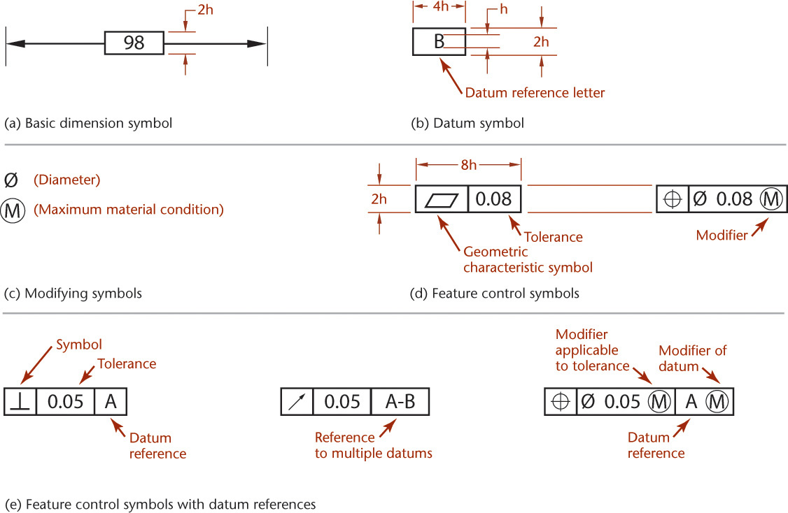
Figure 12.40 shows combinations of the various symbols and their meanings. The geometric characteristic symbols and the supplementary symbols are explained below with material adapted from ANSI/ASME Y14.5M-2009:
Basic dimension symbols use an enclosing frame, as shown in Figure 12.40a and below. The basic dimension is the value used to describe the theoretically exact size, shape, or location of a feature. It is the basis from which permissible variations are established either by specifying tolerances on other dimensions, by tolerances given in notes, or by using feature control frames.

Datum identifying symbols consist of a capital letter in a square frame and a leader line extending from the frame to the concerned feature and terminating with a triangle. The triangle may be filled or not filled. Letters of the alphabet (except I, O, Q, X, Y, and Z) are used as datum identifying letters.

Supplementary symbols include the symbols for MMC (maximum material condition—or minimum hole diameter, maximum shaft diameter) and LMC (least material condition—or maximum hole diameter, minimum shaft diameter), as shown in Figure 12.40c. The abbreviations MMC and LMC are also used in notes (see also Table 12.6).
12.40 Use of Symbols for Tolerance of Position and Form (Reprinted from ASME Y14.5M-1994 (R2004), by permission of The American Society of Mechanical Engineers. All rights reserved.)
When needed, the symbol for diameter precedes the specified tolerance in a feature control symbol, as shown in Figure 12.40d. For narrative notes, you can use the abbreviation DIA for diameter.
Combined symbols are found when individual symbols, datum reference letters, and needed tolerances are combined in a single frame, as shown in Figure 12.40e.
Form tolerance is given by a feature control symbol made up of a frame around the appropriate geometric characteristic symbol plus the allowable tolerance. A vertical line separates the symbol and the tolerance, as shown in Figure 12.40d. Where needed, the tolerance should be preceded by the symbol for the diameter and followed by the symbol for MMC or LMC.
Reference to a datum is indicated in the feature control frame by placing the datum reference letter after either the geometric characteristic symbol or the tolerance. Vertical lines separate the entries, and where applicable, the datum reference letter entry includes the symbol for MMC or LMC, as shown in Figure 12.40e.
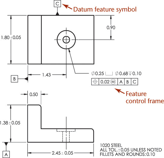
Figure 12.41 shows how geometric dimensioning and tolerance symbols are applied to a drawing. Understanding datum surfaces and features is important to the application of geometric dimensioning and tolerancing.

12.41 Application of Symbols to Position and Form Tolerance Dimensions (Reprinted from ASME Y14.5-2009, by permission of The American Society of Mechanical Engineers. All rights reserved.)
12.13 Datum Features
Datum features are used as references to control other features on the part. For example, when defining the location of a hole, you can specify its distance from a datum surface on the part. Datums should be geometric features on the actual part, such as a point or a plane as shown in Figure 12.42. Centerlines on drawings are not used as datums.

12.42 Placement of Datum Feature Symbol (Reprinted from ASME Y14.5M-1994 (R2004), by permission of The American Society of Mechanical Engineers. All rights reserved.)
Datum Features versus Datum Feature Simulator
Datums are theoretically exact points, axes, lines, or planes. A datum feature is a physical feature on the part that is being manufactured or inspected. It is identified on the drawing by a datum feature symbol, such as shown in Figure 12.43. When specifying datum features keep in mind that the feature should
• Correspond to the mating feature on another part to which the fit is required,
• Be readily accessible on the part, and
• Be sufficiently large to permit its use for making measurements and alignments.
12.43 Datum feature symbols identify datum surfaces on a drawing.
Datum features, because they are features of the actual part, are inherently imperfect. When a part is inspected to determine if it meets the tolerance requirement specified in relation to a datum, a datum feature simulator is used. The datum feature simulator is a boundary derived from the datum feature. It is typically the inverse of the datum feature. For example, if the datum feature is a hole, then the datum feature simulator is a positive cylinder, such as a go/no-go plug gage. A datum feature simulator can be one of two types: a theoretically exact datum feature simulator or a physical datum feature simulator.
An example of a theoretically exact datum feature simulator is a plane defined in a CAD system. An example of a physical datum feature simulator is a precisely finished granite slab on which a part to be inspected is placed. Because physical datum feature simulators themselves cannot be exactly perfect, the tolerances defined for a feature must take into account the imperfections in precision gages and fixtures. Standards for these are specified in ASME Y14.43.
Datum Reference Frame
Imagine trying to measure the location of a hole in an air hockey puck while it is floating on an air hockey table. That would be difficult! A datum reference frame provides a framework for eliminating the translations (movement) and rotations of which the free part is capable.
A datum reference frame is often defined by three mutually perpendicular planes, used to immobilize the part to be inspected and provide a way to make accurate and repeatable measurements. The datum feature symbols on the drawing identify the primary datum, secondary datum, and tertiary datum (meaning first, second, and third) (Figure 12.43).
The datum reference frame is a theoretical construct that does not exist on the actual part. It is established from the datum features identified on the part drawing. Often, a fixture is used where the primary datum surface contacts the measurement fixture at three points, thus defining a plane. Once the primary datum plane is established, only two additional contact points are needed to establish the secondary datum plane. Once the primary and secondary planes are established, a single additional point will establish the tertiary datum plane (see Figure 12.44). The datum reference frame is established from the datum feature simulators, not from the datum features themselves.

Step by Step: Constraining Degrees of Freedom
Datums listed in a feature control frame are applied to constrain degrees of freedom of the part with respect to a datum reference frame. Datums can be identified to constrain the degrees of freedom of the part to immobilize it for inspection.
The free part shown here can translate (move) back and forth in the x, y, and z directions. It can also have rotations u, v, and w. It is said to have six degrees of freedom owing to these motions.

![]() If the part rests on datum plane A, the part can no longer move in the z direction, nor can it rotate in u or v motions. Now it has three degrees of freedom. It can rotate in w, and move in x and y.
If the part rests on datum plane A, the part can no longer move in the z direction, nor can it rotate in u or v motions. Now it has three degrees of freedom. It can rotate in w, and move in x and y.
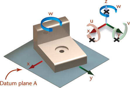
![]() Adding datum B further restricts the motion of the part. Now it can no longer move in the y direction or rotate in w. It has one remaining degree of freedom, motion in x.
Adding datum B further restricts the motion of the part. Now it can no longer move in the y direction or rotate in w. It has one remaining degree of freedom, motion in x.

![]() Adding datum C restricts the final motion to produce a part that is stationary. The x, y, and z axes may be specified on the drawing and in the feature control frame as needed for clarity.
Adding datum C restricts the final motion to produce a part that is stationary. The x, y, and z axes may be specified on the drawing and in the feature control frame as needed for clarity.

Datum Targets
Datum targets, as shown in Figure 12.45, can be added to drawings when necessary to specify where points or areas of contact for the simulated datum should occur on the part. You can find detailed information on datum targets and inspection methods in standard geometric dimensioning and tolerancing texts.
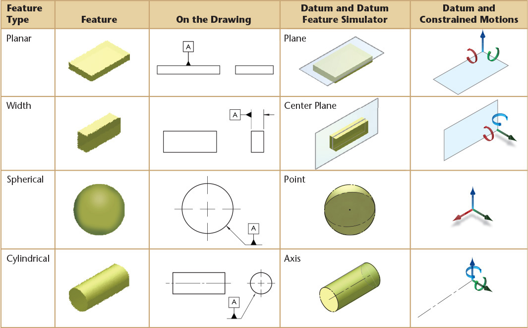
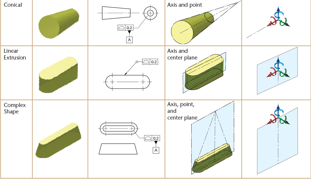
Table 12.7 shows examples of typical datum features, how the feature is identified as a datum on the drawing, and a pictorial view of the theoretically exact datum feature simulator. The final column shows which motions would be constrained. In the application of a feature control frame, the degrees of freedom constrained will depend on whether the datum feature is referenced as a primary, secondary, or tertiary datum feature. The examples in the table show simple cases with single features.
12.14 Positional Tolerances
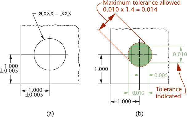
Figure 12.46a shows a hole located from two surfaces at right angles to each other. The center may lie anywhere within a square tolerance zone, with sides equal to the tolerances. Using coordinate dimensioning, the total variation allowed along the diagonals of the square is 1.4 times the indicated tolerance. In contrast, when a circular area is used to specify the allowable variation for the center’s location, up to 57% more parts may measure acceptable.
If four holes are dimensioned with rectangular coordinates, as in Figure 12.47a, the tolerance describes a square zone in which the center of the hole must be located (Figure 12.47b). This square-shaped zone allows the center of the hole to vary more in the diagonal direction than the stated tolerance value.
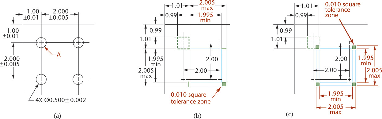
In Figure 12.47a, hole A is located from the corner of the part, and the other three are located from A. The tolerances applied to the locations for hole A result in a square tolerance zone. The other three holes are located from the previous hole. Their tolerances produce square zones whose locations vary according to the actual location of hole A. Two of the many possible zone patterns are shown in Figures 12.47b and c.
With the dimensions shown in Figure 12.47a, the resulting parts may not fit with mating parts, even though they meet the drawing tolerances.
Tolerancing features based on their geometry can prevent these problems. Geometric tolerancing controls the shape of the tolerance zone using geometric characteristics in the feature control frame. This is also called true-position dimensioning. Using it, the tolerance zone for holes can be circular, with the size of the circle depending on the variation permitted from true position as specified using a feature control frame (see Figure 12.48).

12.48 True-Position Dimensioning (Reprinted from ASME Y14.5M-1994 (R2004), by permission of The American Society of Mechanical Engineers. All rights reserved.)
Methods for relating feature control symbols to the feature were shown in Figure 12.41. The following are preferred:
1. Add the symbol to a feature’s note or dimension.
2. Run a leader from the symbol to the feature.
3. Attach the side, end, or corner of the symbol frame to an extension line from the feature.
4. Attach a side or end of the symbol frame to the dimension line basic to the feature.
A basic dimension specifies the theoretically exact position of a feature. The location of each feature, such as a hole, slot, or stud, is given by untoleranced basic dimensions identified by an enclosing box. True position is usually established with respect to a datum.
A feature control frame for a positional tolerance describes a cylindrical tolerance zone with a diameter equal to the positional tolerance and a length equal to the length of the feature unless otherwise specified (Figure 12.48). The axis of the hole center must be within the cylindrical zone, as shown in Figure 12.49.
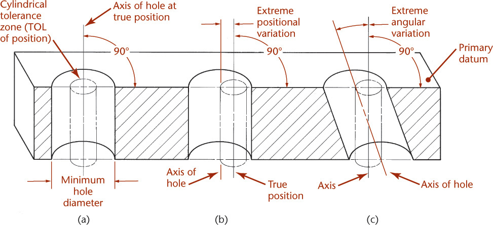
12.49 Cylindrical Tolerance Zone (Reprinted from ASME Y14.5M-1994 (R2004), by permission of The American Society of Mechanical Engineers. All rights reserved.)
The centerline of the hole may coincide with the centerline of the cylindrical tolerance zone (Figure 12.49a). It may be parallel to it but displaced so that it remains within the tolerance cylinder (Figure 12.49b), or it may be inclined and remain within the tolerance cylinder (Figure 12.49c).
A positional tolerance specifies that all elements on the hole surface must be on or outside a cylinder whose diameter is equal to the minimum diameter or the maximum diameter of the hole minus the positional tolerance diameter, when the centerline of the cylinder is located at true position.
Special untoleranced basic dimensions locate features at true position, avoiding tolerance accumulation, as shown in Figure 12.50.
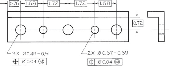
The exact locations of the true positions are given by untoleranced basic dimensions, ensuring that general tolerances are not applied to them. Basic dimensions are enclosed in a box to indicate that no tolerance applies to them, Alternatively, this information can be stated in a clearly worded note, such as UNTOLERANCED DIMENSIONS ARE BASIC.
Features such as slots may vary on either side of a true-position plane, as shown in Figure 12.51.

12.51 Positional Tolerancing for Symmetry (Reprinted from ASME Y14.5M-1994 (R2004), by permission of The American Society of Mechanical Engineers. All rights reserved.)
12.15 Maximum Material Condition
Maximum material condition, or MMC, means that a feature of a finished product contains the maximum amount of material permitted by the toleranced dimensions shown for that feature. Holes, slots, or other internal features are at MMC when at minimum size. Shafts, pads, bosses, and other external features are at MMC when at their maximum size. A feature is at MMC for both mating parts when the largest shaft is in the smallest hole and there is the least clearance between the parts.
In assigning positional tolerance to a hole, consider the size limits of the hole. If the hole is at MMC, or its smallest size, the positional tolerance is not affected, but if the hole is larger, the available positional tolerance is greater. In Figure 12.52a, two half-inch holes are shown. If they are exactly .500″ in diameter (MMC, or smallest size) and are exactly 2.000″ apart, a gage made of two round pins .500″ in diameter fixed in a plate 2.000″ apart, as shown in Figure 12.52b, should fit into them. However, the center-to-center distance between the holes may vary from 1.993″ to 2.007″ as specified by the ∅.007 positional tolerance in the feature control frame in Figure 12.52a.
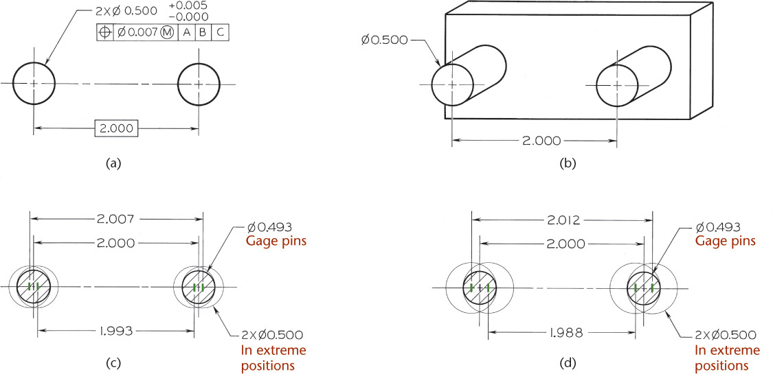
12.52 Maximum and Minimum Material Conditions—Two-Hole Pattern (Reprinted from ASME Y14.5M-1994 (R2004), by permission of The American Society of Mechanical Engineers. All rights reserved.)
If the .500″ diameter holes are at their extreme positions, as in Figure 12.52c, the pins in the gage would have to be .007″ smaller, or .493″ in diameter, to fit into the holes. If the .500″ diameter holes are located at the maximum distance apart, the .493″ diameter gage pins would contact the inner sides of the holes; and if the holes are located at the minimum distance apart, the .493″ diameter pins would contact the outer surfaces of the holes, as shown. If gage-maker’s tolerances are not disregarded, the gage pins would have to be .493″ in diameter and exactly 2.000″ apart if the holes are .500″ in diameter, or MMC.
If the holes are .505″ in diameter—that is, at maximum size—the same .493″ diameter gage pins at 2.000″ apart will fit with the inner sides of the holes contacting the inner sides of the gage pins and the outer sides of the holes contacting the outer sides of the gage pins, as shown in Figure 12.52d. When the holes are larger, they may be farther apart and still fit the pins. In this case they may be 2.012″ apart, which is beyond the tolerance permitted for the center-to-center distance between the holes. Similarly, the holes may be as close together as 1.988″ from center to center, which again is outside the specified positional tolerance.
Thus, when holes are at maximum size, a greater positional tolerance becomes available. Because all features may vary in size, it is necessary to make clear on the drawing at what basic dimension the true position applies. In all but a few exceptional cases, when the holes are larger, the additional positional tolerance is available without affecting the function. Parts can still be freely assembled whether or not the holes or other features are within the specified positional tolerance. This practice has been recognized and used in manufacturing for years in designing fixed-pin gages, which are commonly used to inspect parts and control the least favorable condition of assembly. It has become common practice for both manufacturing and inspection to assume that positional tolerance applies to MMC and that greater positional tolerance becomes permissible when the part is not at MMC.
To avoid misinterpretation as to whether the MMC applies, it should be clearly stated by adding MMC symbols to each applicable tolerance on the drawing or by a document referenced on the drawing. When MMC is not specified on the drawing with respect to an individual tolerance, datum reference, or both, these rules apply:
1. True-position tolerances and related datum references apply at MMC.
2. All applicable geometric tolerances—such as angularity, parallelism, perpendicularity, concentricity, and symmetry tolerances, including related datum references—apply regardless of feature size when no modifying symbol is specified. Circular runout, total runout, concentricity, and symmetry are applicable regardless of feature size and cannot be modified to MMC or LMC.
3. No element of the actual feature will extend beyond the envelope of the perfect form at MMC. Maximum material condition or least material condition must be specified on the drawing where it is required.
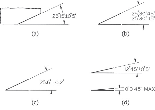
12.16 Tolerances of Angles
Bilateral tolerances have traditionally been given on angles as shown in Figure 12.53. With bilateral tolerances, the wedge-shaped tolerance zone increases as the distance from the vertex of the angle increases.
If an angular surface is located by a linear and an angular dimension, as shown in Figure 12.54a, the surface must lie within a tolerance zone, as shown in Figure 12.54b. The angular zone will be wider as the distance from the vertex increases. To avoid the accumulation of tolerance farther out from the angle’s vertex, the basic angle tolerancing method, shown in Figure 12.54c, is recommended. The angle is indicated as a basic dimension, and no angular tolerance is specified. The tolerance zone is now defined by two parallel planes, resulting in improved angular control, as shown in Figure 12.54d.
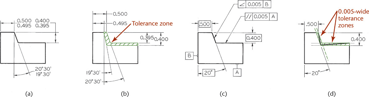
12.54 Angular Tolerance Zones (Reprinted from ASME Y14.5M-1994 (R2004), by permission of The American Society of Mechanical Engineers. All rights reserved.)
Use specific controls such as angular geometric controls or a basic dimension to prevent general tolerances from applying to implied right angles.
12.17 Form Tolerances for Single Features
Straightness, flatness, roundness, cylindricity, and in some instances, profile, are form tolerances that apply to single features.
The straightness tolerance specifies a tolerance zone within which an axis or all points of the considered element must lie (Figure 12.55). Straightness is a condition in which an element of a surface or an axis is a straight line.
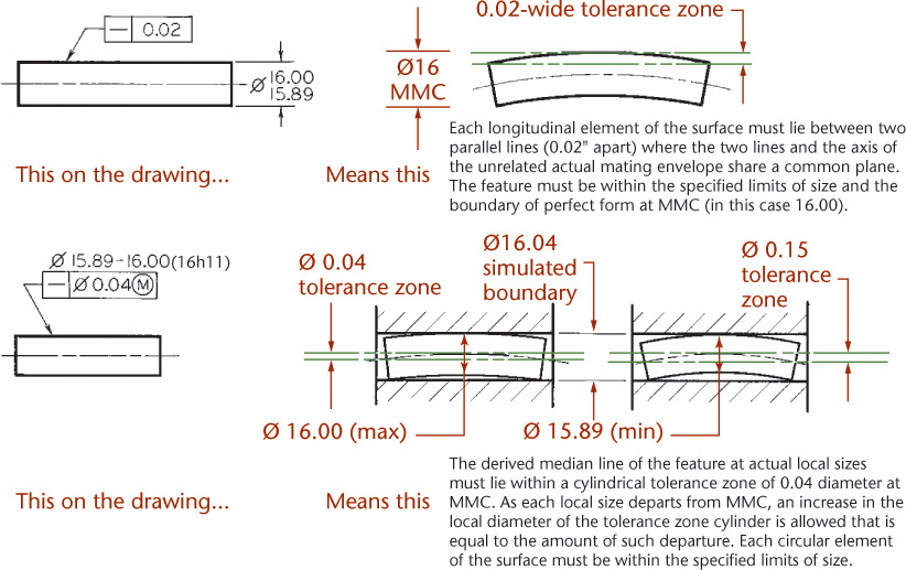
12.55 Specifying Straightness (Reprinted from ASME Y14.5M-1994 (R2004), by permission of The American Society of Mechanical Engineers. All rights reserved.)
The flatness tolerance specifies a tolerance zone defined by two parallel planes within which the surface or derived median plane must lie (Figure 12.56). Flatness is the condition of a surface or derived median plane having all elements in one plane.
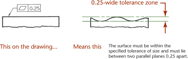
12.56 Specifying Flatness (Reprinted from ASME Y14.5M-1994 (R2004), by permission of The American Society of Mechanical Engineers. All rights reserved.)
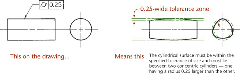
The circularity (roundness) tolerance specifies a tolerance zone bounded by two concentric circles within which each circular element of the surface must lie (Figure 12.57). Roundness is a condition of a cone or cylinder where all points of the surface intersected by any plane perpendicular to a common axis are equidistant from that axis. For a sphere, all points of the surface intersected by any plane passing through a common center are equidistant from that center.

12.57 Specifying Roundness for a Cylinder or Cone (Reprinted from ASME Y14.5M-1994 (R2004), by permission of The American Society of Mechanical Engineers. All rights reserved.)
The cylindricity tolerance specifies a tolerance zone bounded by two concentric cylinders within which the surface must lie (Figure 12.58). This tolerance applies to both circular and longitudinal elements of the entire surface. Cylindricity is a condition of a surface of revolution in which all points of the surface are equidistant from a common axis. When no tolerance of form is given, many possible shapes may exist within a tolerance zone (Figure 12.59).
12.58 Specifying Cylindricity (Reprinted from ASME Y14.5M-1994 (R2004), by permission of The American Society of Mechanical Engineers. All rights reserved.)

The profile tolerance specifies a uniform boundary or nonuniform boundary (using the unequally disposed symbol) along the true profile within which all elements of the surface or single elements of the surface must lie (Figures 12.60 and 12.61). A profile is an outline of a surface, a shape made up of one or more features, or a two-dimensional element of one or more features. A digital file or drawing view defines the true profile.
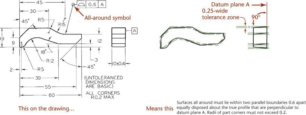
12.60 Specifying Profile of a Surface All Around (Reprinted from ASME Y14.5M-1994 (R2004), by permission of The American Society of Mechanical Engineers. All rights reserved.)

12.61 Specifying Profile of a Surface Between Points (Reprinted from ASME Y14.5M-1994 (R2004), by permission of The American Society of Mechanical Engineers. All rights reserved.)
12.18 Orientations for Related Features
Angularity, parallelism, perpendicularity, and in some instances, profile, are tolerances that apply to related features. These tolerances control the orientations of features to one another Orientation tolerances do not control the location of the features.
Angularity specifies the condition of a surface, feature’s center plane, or feature’s axis at a specified angle from a datum plane or datum axis.
Perpendicularity specifies the condition of a surface, feature’s center plane, or feature’s axis at a right angle from a datum plane or datum axis. This is the same as angularity when specifying a 90° angle. Either method can be used.
Parallelism specifies the condition of a surface or feature’s center plane equidistant from a datum plane or for a feature’s axis, equidistant along its length from one or more datum planes or datum axes.
Orientation tolerances must be related to one or more datums. Only the rotational degrees of freedom are constrained when an orientation tolerance is specified. Orientation tolerances may specify the following:
• A zone defined by two parallel planes at the specified basic angle from, or perpendicular to, or parallel to one or more datum planes or a datum axis. The surface or center plane of the feature must lie within this zone.
• A zone defined by two parallel planes at the specified basic angle from, perpendicular to, or parallel to one or more datum planes or a datum axis. The axis of the feature must lie within this zone.
• A cylindrical zone at the specified base angle from, or perpendicular to, or parallel to one or more datum planes or a datum axis. The axis of the feature must lie within this zone.
• A zone defined by two parallel lines at the specified basic angle from, or perpendicular to, or parallel to one or more datum planes or a datum axis. Any line element of the feature must lie within this zone.
The angularity tolerance specifies a tolerance zone defined by two parallel planes at the specified basic angle from a datum plane or axis within which the surface or the axis of the feature must lie (Figure 12.62).
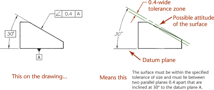
12.62 Specifying Angularity for a Plane Surface (Reprinted from ASME Y14.5M-1994 (R2004), by permission of The American Society of Mechanical Engineers. All rights reserved.)
The parallelism tolerance specifies a tolerance zone defined by two parallel planes or lines parallel to a datum plane or axis, respectively, within which the surface or axis of the feature must lie (Figures 12.63–12.65). Also, a parallelism tolerance may specify a cylindrical tolerance zone parallel to a datum axis within which the axis of the feature must lie.
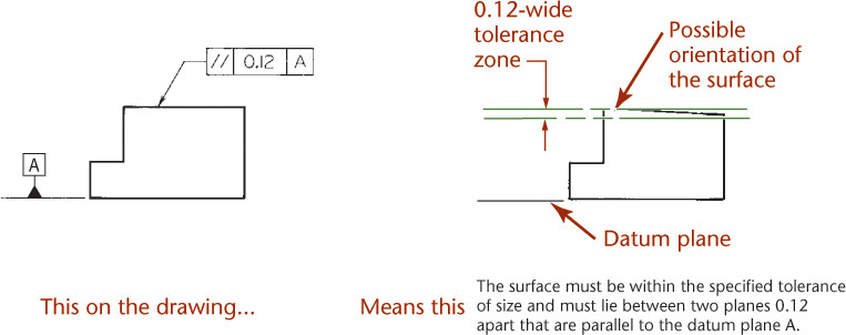
12.63 Specifying Parallelism for a Plane Surface (Reprinted from ASME Y14.5M-1994, by permission of The American Society of Mechanical Engineers. All rights reserved.)

12.64 Specifying Parallelism for an Axis Feature (Reprinted from ASME Y14.5M-1994 (R2004), by permission of The American Society of Mechanical Engineers. All rights reserved.)
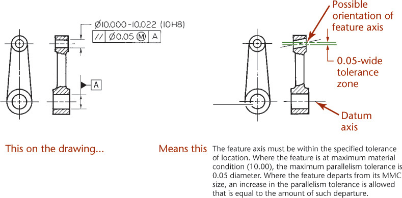
12.65 Specifying Parallelism for an Axis Feature at MMC (Reprinted from ASME Y14.5M-1994 (R2004), by permission of The American Society of Mechanical Engineers. All rights reserved.)
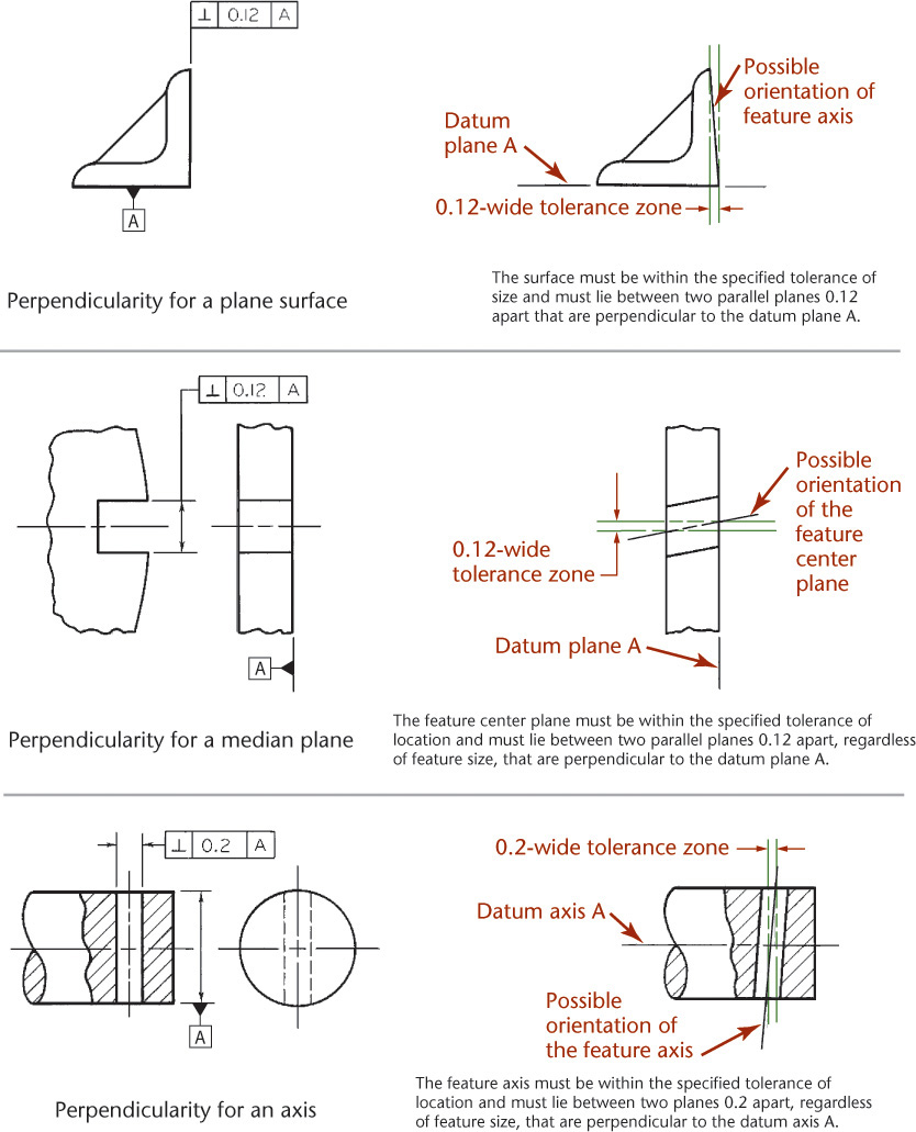
12.66 Specifying Perpendicularity (Reprinted from ASME Y14.5M-1994 (R2004), by permission of The American Society of Mechanical Engineers. All rights reserved.)
The perpendicularity tolerance specifies one of the following:
1. A tolerance zone defined by two parallel planes perpendicular to a datum plane, datum axis, or axis within which the surface of the feature must lie.
2. A cylindrical tolerance zone perpendicular to a datum plane within which the axis of the feature must lie.
(Perpendicularity is the condition of a surface, median plane, or axis that is at 90° to a datum plane or axis.)
The concentricity tolerance specifies a cylindrical (or spherical for those applications) tolerance zone whose axis or center point coincides with a datum axis and within which all cross-sectional axes of the feature being controlled must lie (Figure 12.67). Concentricity is the condition in which the median points of all diametrically opposed elements of a surface of revolution are congruent with a datum axis.
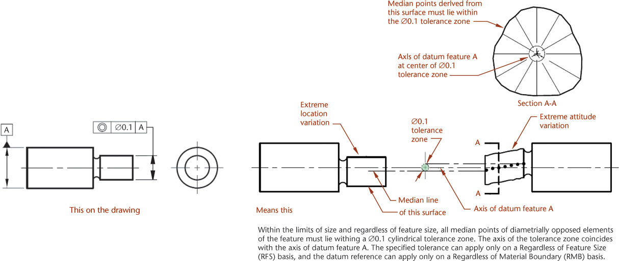
12.67 Specifying Concentricity. (Reprinted from ASME Y14.5-2009, by permission of The American Society of Mechanical Engineers. All rights reserved.)
12.19 Using Geometric Dimensioning and Tolerancing
Geometric dimensioning and tolerancing (GDT) has evolved over the last 40 years to become an indispensable tool for defining parts and features more accurately. GDT not only considers an individual part and its dimensions and tolerances but views that part in relation to its related parts. This allows the designer more latitude in defining the part’s features more accurately by considering not only the part’s dimensions but its tolerances at the initial design stage. GDT also simplifies the inspection process. This is accomplished through the use of ASME standards (ASME-Y14.5M), as we have discussed previously.
Individually manufactured parts and components must eventually be assembled into products. We take for granted that each part of a lawnmower, for example, will mate properly with its other components when assembled. The wheels will slip into their axles, the pistons will fit properly into their cylinders, and so on. Nothing should be too tight or too loose.
Geometric dimensioning and tolerancing, therefore, is important to both the design and manufacturing processes.
Applying GDT principles to the design process requires five steps.
Step 1 Define the part’s functions. It is best to break the part down to its simplest functions. Be as specific as possible. For example, a lawnmower wheel’s functions are to (a) give the product mobility; (b) lift the mowing deck off the ground; (c) add rigidity to the body, and so forth.
Step 2 List the functions by priority. Only one function should have top priority. This step can be difficult, because many parts are designed to incorporate multiple functions. In our lawnmower wheel example, the function with top priority would be to give the product mobility.
Step 3 Define the datum reference frame. This step should be based on your list of priorities. This may mean creating several reference frames, each based on a priority on your list. The frame should be set up in either one, two, or three planes.
Step 4 Control selection. In most cases, several controls will be needed (e.g., runout, position, concentricity, or roughness). Begin with the simplest control. By “simplest” we mean least restrictive. Work from the least restrictive to the most restrictive set of controls.
Step 5 Calculate tolerances. Most tolerances are mathematically based. This step should be the easiest. Apply MMC, RFS, or LMC where indicated. Avoid completing this step first; it should always be your final step.
12.20 Tolerances and Digital Product Definition
Dimensioning and tolerancing can take place directly in the 3D digital database. The electronic file can be transmitted as the digital product definition specifying the shape, size, and finish to the company that will manufacture and/or assemble the parts.
When you create a 3D model, it represents the ideal geometric shape of the part. The part can be manufactured very precisely, but as precision is increased, so is the price of the part. Adding tolerances to the model informs the manufacturer of the accuracy that is required on the finished part for it to function in your design as you intend. Essentially, you need to tell the manufacturer when to stop trying to achieve the level of perfection that is represented in your model.
When you include annotations in the solid model, the annotation should:
• Be in a plane that is clearly associated with the corresponding surface or view;
• Be clearly associated with the corresponding model geometry;
• Be capable of being printed and meet applicable drawing standards; and
• Be possible to display on the screen or turn off.
In general, tolerances and annotations provided directly in the model need to be interpreted to achieve the result that you intend. A combination of drawings and the model, only drawings, or a fully annotated model are all available methods for documenting a design. Each method has its advantages and disadvantages. You should investigate which method is suitable for your use and understand the applicable standards. See Figure 12.68 for examples of tolerancing in CAD. Partially dimensioned drawings should note: SEE DATASET FOR FULL GEOMETRIC DESCRIPTION.

12.68 Tolerances can be added directly to a 3D model so that it can be used as the digital product definition. (Reprinted from ASME Y14.41-2003, by permission of The American Society of Mechanical Engineers. All rights reserved.)
12.21 Computer Graphics
CAD programs generally allow the user to add tolerances to dimension values in the drawings. Geometric dimensioning and tolerancing symbols, finish marks, and other standard symbols are typically available as a part of the CAD program or as a symbol library (see Figures 12.69 and 12.70.

12.69 This dialog box in Autodesk Inventor aids in creating geometric dimensioning and tolerancing symbols. (Autodesk screen shots reprinted courtesy of Autodesk, Inc.)
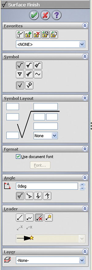
12.70 SolidWorks software makes it easy to select surface finish symbols. (Courtesy of SolidWorks Corporation.)
Geometric dimensioning and tolerancing has become an essential part of today’s manufacturing industry. To compete in today’s marketplace, companies are required to develop and produce products of the highest quality, at lowest cost, and guarantee on-time delivery. Although considered by most to be a design specification language, GDT is a manufacturing and inspection language as well, providing a means for uniform interpretation and understanding by these various groups. It provides both a national and international contract base for customers and suppliers.
CAD at Work: Using SolidWorks to Perform a Fit Study
Tolerances are important to consider not just for each individual part but also for the entire assembly. Tolerance variations may accumulate from feature to feature of a part, and tolerances may also stack up from part to part in an assembly. One way to analyze the tolerances in the design of your assembly is to do a fit study. SolidWorks software is one modeler that has some useful tools for performing a fit study.
You can use the Interference Detection command in SolidWorks to show you where any two parts overlap in the model. To perform a fit study, modify the features of interest so they are at the upper size range of the allowable tolerance. Then, use the Interference Detection selection to display the dialog box shown in the figure. Click Calculate to display the names of components that overlap in the Results portion of the dialog box. Once you have checked the features sized at the upper extremes of the tolerance limits, set the feature to the lower size limit, and repeat the interference detection.
You can use SolidWorks to store configurations of each part. You can configure the model at the maximum material condition and at the minimum and store both. This allows you to quickly set the part model to a particular case for your fit study and then check the interferences.
As you can imagine, the more complex the assembly, the more valuable this CAD tool will be to you.
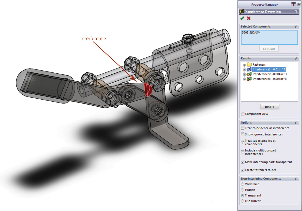
Areas that interfere in the assembly model are highlighted during interference detection. The length of this wheel lock lever part has been modified to exaggerate the material overlap when this part interferes. (Courtesy of Dynojet Research, Inc.)

Unilateral tolerances are specified for hole sizes. (Courtesy of Dynojet Research, Inc.)
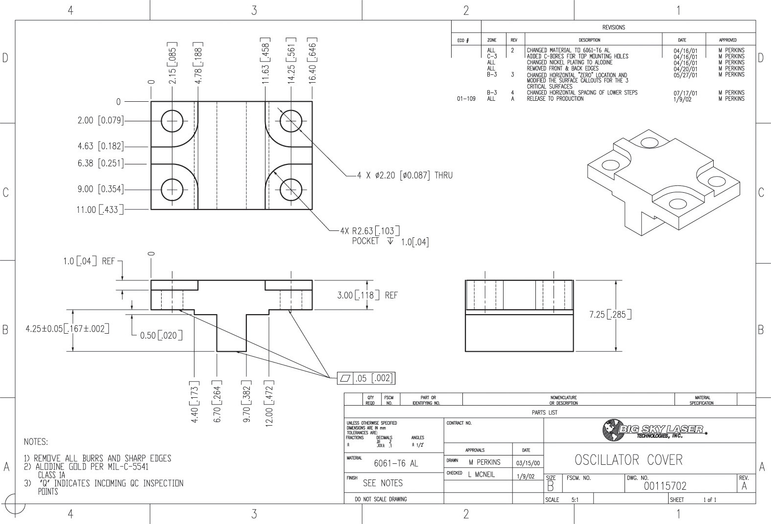

Dimensioned and Toleranced Part Drawing Using Limit, Variation, and Geometric Dimensioning and Tolerancing (Courtesy of Dynojet Research, Inc.)
Actual Minimum Material Envelope
Basic Angle Tolerancing Method
Concentricity Tolerance
Geometric Dimensioning and Tolerancing (GDT)
International Tolerance Grade (IT)
Roundness (Circularity) Tolerance
Chapter Summary
• Tolerance dimensioning describes the minimum and maximum limits for the size or the location of a feature.
• There are several types of dimensioning tolerances, including limit dimensions, unilateral tolerances, bilateral tolerances, and geometric tolerancing.
• Hole tolerance systems are the most commonly used tolerance systems because they assume the hole is nominal size and adjust the shaft to accommodate the tolerance.
• The amount of space between two mating parts at maximum material condition is called the allowance.
• Mating parts with large allowances are classified as having a clearance fit or a running and sliding fit.
• Mating parts with negative allowances are classified as having an interference fit or force fit.
• Mating parts are designed around a nominal size and class of fit. Other tolerances are calculated from these two values.
• High-quality parts are often dimensioned with geometric tolerancing to ensure that the size, shape, and relative geometric characteristics are properly defined.
• Datums can be used to define which degrees of freedom to restrict to make accurate and repeatable measurements.
• GDT has become an essential part of today’s manufacturing industry. GDT is not only a design language but an inspection language as well.
2. Draw three different geometric tolerances that reference a datum. Label the information in each box.
3. Why is the hole system more common than the shaft system for determining fits?
4. Give five examples of nominal sizes in everyday life. What is the purpose of a nominal size?
5. Give an example of two parts that would require a running and sliding fit. A force fit.
6. List five classes of fit.
7. Can one part have an allowance? Why?
8. Can two parts have a tolerance? Why?
9. Give an example of how GDT could be used as both a design and inspection tool.
10. Draw an isometric sketch of a cube and label the six degrees of freedom its motion can exhibit.
11. List the five steps required to apply GDT to the design process.
Chapter Exercises
Design Project
Exercise 12.1 Design a bike rack using standard tubing products and standard fittings. Provide a means for mounting the rack to concrete. What accuracy is required for your design to function? Research the manufacturing accuracy for the parts you specify. What is the maximum allowance your mounting can be off and still allow the parts to fit?
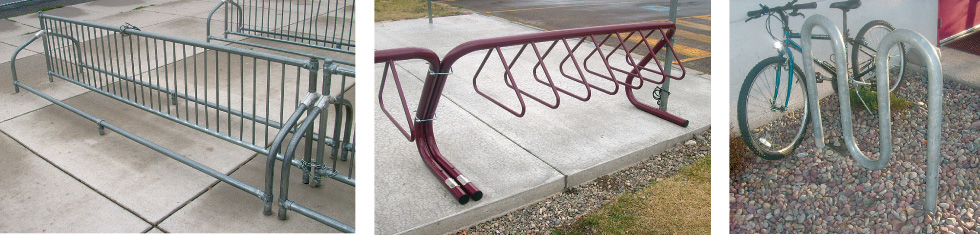
Tolerancing Projects
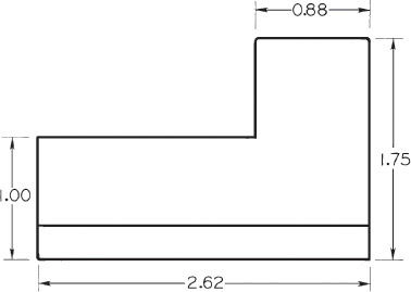
Exercise 12.2 Sketch the figure shown. Use either limit dimensions, bilateral tolerances, or geometric tolerancing to add a hole to the left end of the part, located .50″ from the bottom surface and 2″ from the right end of the part. The location should be accurate to ±.005 and its size accurate to within ±.002.

Exercise 12.3 Add geometric dimensioning and tolerancing symbols to the drawing to do the following: (a) Control the flatness of the bottom surface to a total tolerance of .001. (b) Control perpendicularity of the left surface and bottom surface to .003. (c) Control the tolerance for the 30° angle to .01.

Exercise 12.4 You have been tasked with mounting a dielectric mirror at a 45° angle. This will be done by creating a mount out of 6061-T6 aluminum machined with a 45° face. The face will have a machined counterbore in which to mount the optic and three bond spots to attach the optic. The specifications for the design are:
• Reference the provided drawing for a stock 1″ dielectric mirror.
• The diameter for the counterbore must be .005″ to .010″ larger than the maximum diameter of the optic.
• The optic must sit at a minimum of .010″ and maximum of .020″ above the mounting surface.
• The optic will be bonded to the mount using ultraviolet curing adhesive. The adhesive bond spots will be .100″ diameter by .050″ deep, equally spaced around the perimeter of the optic counterbore.
• The center point of the outer surface of the optic will be located 1 ± .05″ from the bottom of the mount.
• The mount will be attached to a laser structure using two 6-32 socket head cap screws.
Answer these questions:
1. What diameter of counterbore is used to ensure the counterbore is .005″ to .010″ larger than the maximum diameter of the optic?
2. What depth of counterbore is used to ensure a .010″/.020″ protrusion height of the optic?
3. Create a full mechanical drawing with appropriate tolerances for the designed mount.
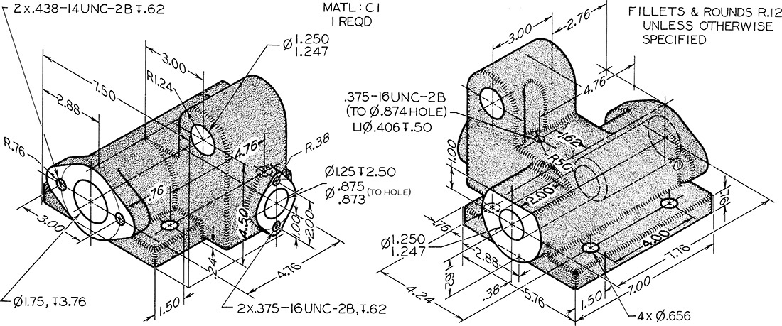
Exercise 12.5 Create a detail drawing for the automatic stop box shown in the two isometric views. Use standardized dimensioning and tolerancing symbols to replace notes as much as possible.
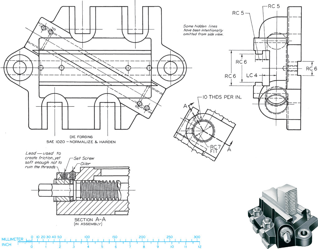
Exercise 12.6 Complete the following for this jaw base for a chuck jaw, with top, right-side, and partial auxiliary views shown. (a) Create top, left-side (beside top), front, and partial auxiliary views complete with dimensions, if assigned. Use metric or decimal-inch dimensions. Use American National Standard tables for indicated fits or convert for metric values. See Appendices 4–13. (b) Create solid models for parts and assembly. Make detail drawings for parts and provide tolerances for critical fits. Use a general tolerance note for all other sizes.
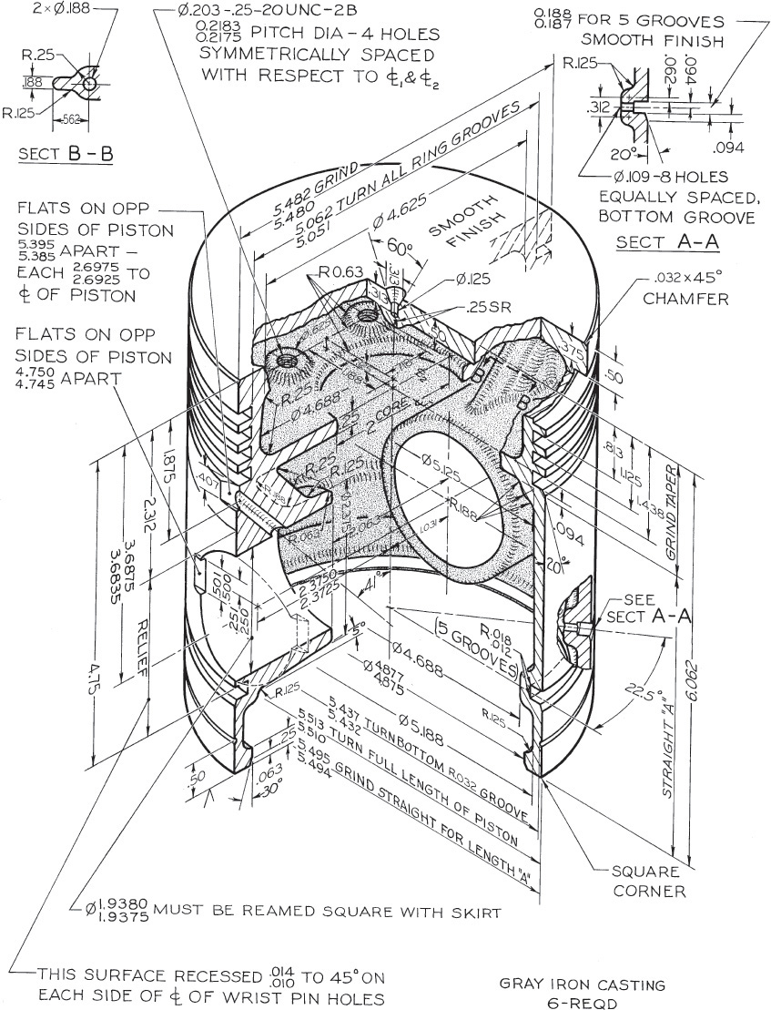
Exercise 12.7 For this Caterpillar tractor piston, make a detail drawing full size. If assigned, use the unidirectional decimal-inch system, converting all fractions to two-place decimal dimensions, or convert all dimensions to metric. Use standard symbols for dimensioning and tolerancing to replace notes.