Chapter Thirteen. Threads, Fasteners, and Springs
Objectives
After studying the material in this chapter, you should be able to:
1. Define and label the parts of a screw thread.
2. Identify various screw thread forms.
3. Draw detailed, schematic, and simplified threads.
4. Define typical thread specifications.
5. Identify various fasteners and describe their use.
6. Draw various screw head types.
Refer to the following standards:
• ANSI/ASME B1.1
• ANSI/ASME B1.7M
• ANSI/ASME B1.13M
• ANSI/ASME B17.11
• ANSI/ASME Y14.6
Understanding Threads and Fasteners
Screw threads are vital to industry. They are designed for hundreds of different purposes. The three basic applications are:
1. To hold parts together (Figure 13.1).

2. To provide for adjustment between parts (Figure 13.2).
3. To transmit power (Figure 13.3).

The shape of the helical (spiral shaped) thread is called the thread form. The metric thread form is the international standard, although the unified thread form is common in the United States. Other thread forms are used in specific applications.
3D CAD software may automatically depict fasteners inserted into the model using simplified thread representation in drawing views and may assist in creating proper callouts. The thread specification is a special leader note that defines the type of thread or fastener. This is an instruction for the shop technician so the correct type of thread is created during the manufacturing process.
The Standardization of Screw Threads
Once, there was no such thing as standardization. Nuts made by one manufacturer would not fit the bolts of another. In 1841 Sir Joseph Whitworth started crusading for a standard screw thread, and soon the Whitworth thread was accepted throughout England.
In 1864 the United States adopted a thread proposed by William Sellers of Philadelphia, but the Sellers nuts would not screw onto a Whitworth bolt or vice versa. In 1935 the American standard thread, with the same 60° V form of the old Sellers thread, was adopted in the United States.
Still, there was no standardization among countries. In peacetime it was a nuisance; in World War I it was a serious inconvenience; and in World War II the obstacle was so great that the Allies decided to do something about it. Talks began among the Americans, British, and Canadians, and in 1948 an agreement was reached on the unification of American and British screw threads. The new thread was called the Unified screw thread, and it represented a compromise between the American standard and Whitworth systems, allowing complete interchangeability of threads in three countries.
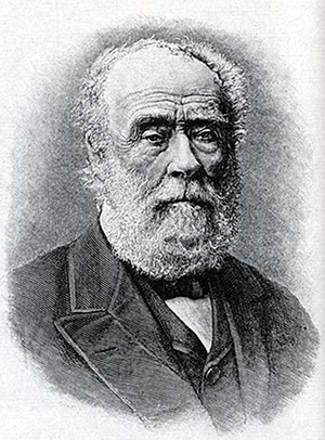
Sir Joseph Whitworth (Courtesy of National Park Service.)
In 1946 a committee called the International Organization for Standardization (ISO) was formed to establish a single international system of metric screw threads. Consequently, through the cooperative efforts of the Industrial Fasteners Institute (IFI), several committees of the American National Standards Institute, and the ISO representatives, a metric fastener standard was prepared.
*For a listing of ANSI standards for threads, fasteners, and springs, see page A-1.
Screw Thread Terms
The following definitions apply to screw threads in general and are illustrated in Figure 13.4. For additional information regarding specific Unified and metric screw thread terms and definitions, refer to the appropriate standards.
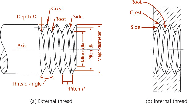
Screw thread A ridge of uniform cross section in the form of a helix on the external or internal surface of a cylinder.
External thread A thread on the outside of a member, as on a shaft.
Internal thread A thread on the inside of a member, as in a hole.
Major diameter The largest diameter of a screw thread (for both internal and external threads).
Minor diameter The smallest diameter of a screw thread (for both internal and external threads).
Pitch The distance from a point on a screw thread to a corresponding point on the next thread measured parallel to the axis. In the United States, the pitch is equal to 1 divided by the number of threads per inch.
Pitch diameter The diameter of an imaginary cylinder passing through the threads where the widths of the threads and the widths of the spaces would be equal.
Lead The distance a screw thread advances axially in one turn.
Angle of thread The angle between the sides of the thread measured in a plane through the axis of the screw.
Crest The top surface joining the two sides of a thread.
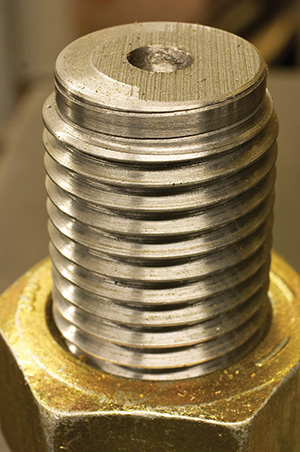
Close-Up View of Threaded Nut and Bolt (Courtesy of Glenj/iStockphoto.com.)
Root The bottom surface joining the sides of two adjacent threads.
Side The surface of the thread that connects the crest with the root. Axis of screw The longitudinal centerline through the screw.
Depth of thread The distance between the crest and the root of the thread measured normal to the axis.
Form of thread The cross section of thread cut by a plane containing the axis.
Series of thread The standard number of threads per inch for various diameters.
A Historical Thread
The concept of the screw thread seems to have occurred first to Archimedes, the third-century-B.C. mathematician who wrote briefly on spirals and designed several simple devices applying the screw principle. By the first century B.C., the screw was a familiar element but was crudely cut from wood or filed by hand on a metal shaft. Not much was heard of the screw thread until the fifteenth century.
Leonardo da Vinci understood the screw principle, and created sketches showing how to cut screw threads by machine. In the sixteenth century, screws appeared in German watches and were used to fasten suits of armor. In 1669, the Frenchman Besson invented the screw-cutting lathe, but this method of production did not take hold for another century and a half; nuts and bolts continued to be made largely by hand. Screw manufacturing began in eighteenth-century England, during the Industrial Revolution.
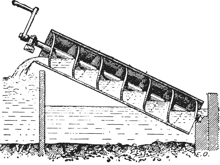
An Archimedean Screw (Copyright Morphart Creation/Shutterstock.)
Screw Thread Forms
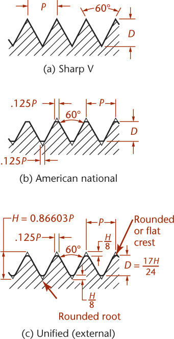
The thread form is the cross-sectional shape of the thread. Various forms of threads are used for different purposes. Figures 13.5–13.7 show some of the typical thread forms.

13.6 Metric, Square, and Acme Screw Thread Forms
Sharp-V thread (60°) is useful for certain adjustments because of the increased friction resulting from the full thread face. It is also used on brass pipe work (Figure 13.5a).
American national thread, with flattened roots and crests, is a stronger thread. This form replaced the sharp-V thread for general use (Figure 13.5b).
Unified thread is the standard thread agreed on by the United States, Canada, and Great Britain in 1948. It has replaced the American national form. The crest of the external thread may be flat or rounded, and the root is rounded; otherwise, the thread form is essentially the same as the American national. Some earlier American national threads are still included in the new standard, which lists 11 different numbers of threads per inch for the various standard diameters, together with selected combinations of special diameters and pitches. The 11 series includes the coarse thread series (UNC or NC), recommended for general use; the fine thread series (UNF or NF), for general use in automotive and aircraft work and in applications where a finer thread is required; the extra fine series (UNEF or NEF), which is the same as the SAE extra fine series, used particularly in aircraft and aeronautical equipment and generally for threads in thin walls; and the 8 series of 4, 6, 8, 12, 16, 20, 28, and 32 threads with constant pitch. The 8UN or 8N, 12UN or 12N, and 16UN or 16N series are recommended for the uses corresponding to the old 8-, 12-, and 16-pitch American national threads. In addition, there are three special thread series—UNS, NS, and UN—that involve special combinations of diameter, pitch, and length of engagement (Figure 13.5c).
Unified extra fine thread series (UNEF) has many more threads per inch for given diameters than any series of the American national or unified. The form of thread is the same as the American national. These small threads are used in thin metal where the length of thread engagement is small, in cases where close adjustment is required, and where vibration is great.
Metric thread is the standard screw thread agreed on for international screw thread fasteners. The crest and root are flat, but the external thread is often rounded if formed by a rolling process. The form is similar to the American national and unified threads but with less depth of thread. The preferred metric thread for commercial purposes conforms to the ISO basic profile M for metric threads. This M profile design is comparable to the unified inch profile, but the two are not interchangeable. For commercial purposes, two series of metric threads are preferred—coarse (general-purpose) and fine—much fewer than previously used (Figure 13.6a).
Square thread is theoretically the ideal thread for power transmission, since its face is nearly at right angles to the axis, but owing to the difficulty of cutting it with dies and because of other inherent disadvantages (such as the fact that split nuts will not readily disengage), square thread has been displaced to a large extent by the acme thread. Square thread is not standardized (Figure 13.6b).
Acme thread is a modification of the square thread and has largely replaced it. It is stronger than the square thread, is easier to cut, and has the advantage of easy disengagement from a split nut, as on the lead screw of a lathe (Figure 13.6c).
Standard worm thread (not shown) is similar to the acme thread but is deeper. It is used on shafts to carry power to worm wheels.
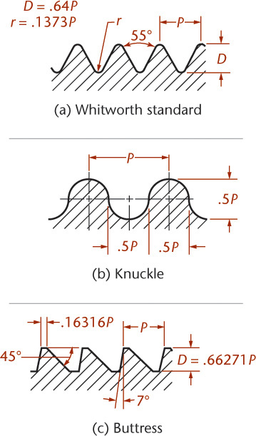
Whitworth thread was the British standard and has been replaced by the unified thread. The uses of Whitworth thread correspond to those of the American national thread (Figure 13.7a).

Knuckle thread is usually rolled from sheet metal but is sometimes cast. In modified forms knuckle thread is used in electric bulbs and sockets, bottle tops, and the like (Figure 13.7b).
Buttress thread is designed to transmit power in one direction only. It is commonly used in large guns, in jacks, and in other mechanisms that have high strength requirements (Figure 13.7c).
A number of different thread forms are defined in various ASME standards that specify requirements for the design and selection of screw threads. For example, the old N thread series has been superseded by the UN series.
Thread Pitch
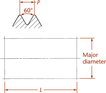
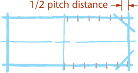
The pitch of any thread form is the distance parallel to the axis between corresponding points on adjacent threads, as shown in Figure 13.8.

For metric threads, this distance is specified in millimeters. The pitch for a metric thread that is included with the major diameter in the thread designation determines the size of the thread—for example, as shown in Figure 13.8b.
For threads dimensioned in inches, the pitch is equal to 1 divided by the number of threads per inch. See Appendix 14 for thread tables giving more information on standard numbers of threads per inch for various thread series and diameters. For example, a unified coarse thread of 1″ diameter has eight threads per inch, and the pitch P equals 1/8″ (.125″).
If a thread has only four threads per inch, the pitch and the threads themselves are quite large, as shown in Figure 13.8a. If there are 16 threads per inch, the pitch is only 1/16″ (.063″), and the threads are relatively small, similar to those in Figure 13.8b.
The pitch or the number of threads per inch can be measured with a scale or with a thread pitch gage (Figure 13.8d).
Thread Series
ASME/ANSI Y14.6, Screw Thread Representation, is a standard for drawing, specifying, and dimensioning threads on drawings.
A thread series is the detail of the shape and number of threads per inch composing different groups of fasteners. Table 13.1 shows the thread series for UN thread. (UNJ and UNR thread series have rounded root contours to aid in preventing stress concentrations that may result from the flat contour of the typical UN thread profile. Both are external thread specifications.)
Table 13.1 Thread Series of UN Thread
Basic Thread Series |
Constant Pitch |
Coarse |
Fine |
Extra Fine |
Special Diameter |
UN |
UN |
UNC |
UNF |
UNEF |
UNS |
UNJ |
UNJ |
UNJC |
UNJF |
UNJEF |
UNJS |
N* |
N |
NC |
NF |
NEF |
NS |
UNR |
UNR |
UNRC |
UNRF |
UNREF |
UNRS |
Five series of threads were used in the old ANSI standards:
Coarse thread A general-purpose thread used for holding. It is designated NC (national coarse).
Fine thread With a greater number of threads per inch, it is used extensively in automotive and aircraft construction. It is designated NF (national fine).
8-pitch thread All diameters have 8 threads per inch. It is used on bolts for highpressure pipe flanges, cylinder-head studs, and similar fasteners. It is designated 8N (national form, 8 threads per inch).
12-pitch thread All diameters have 12 threads per inch. It is used in boiler work and for thin nuts on shafts and sleeves in machine construction. It is designated 12N (national form, 12 threads per inch).
16-pitch thread All diameters have 16 threads per inch. It is used where necessary to have a fine thread regardless of diameter, as on adjusting collars and bearing retaining nuts. It is designated 16N (national form, 16 threads per inch).

The helical shape of thread is similar to the striping on a barber pole.
Right-Hand and Left-Hand Threads
A right-hand thread is one that advances into a nut when turned clockwise, and a left-hand thread is one that advances into a nut when turned counterclockwise, as shown in Figure 13.9. A thread is always considered to be right-hand (RH) unless otherwise specified. A left-hand thread is always labeled LH on a drawing.

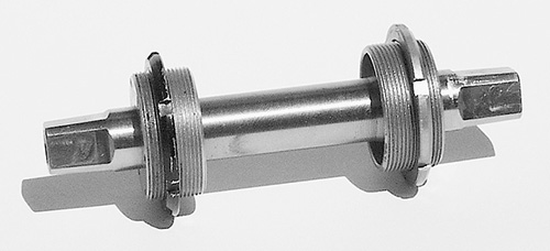
This bottom bracket is used to attach the cranks on a bicycle to the frame. One end has right-hand thread and the other side left-hand thread so the pedal motion won’t unscrew the bottom-bracket bearing cups.
Single and Multiple Threads
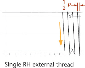
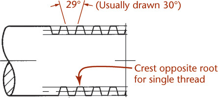
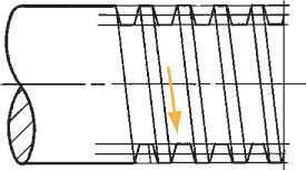
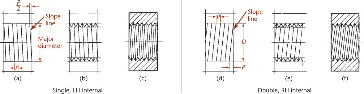
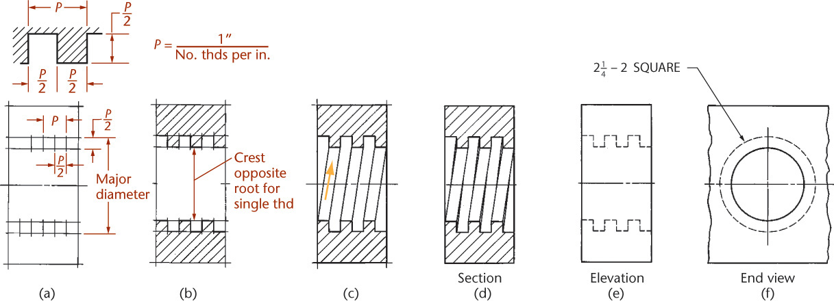
A single thread, as the name implies, is composed of one ridge, and the lead is therefore equal to the pitch. Multiple threads are composed of two or more ridges running side by side. As shown in Figures 13.10a–c, the slope is the hypotenuse of a right triangle whose short side equals .5P for single threads, P for double threads, 1.5P for triple threads, and so on. This relationship applies to all forms of threads. In double threads, the lead is twice the pitch; in triple threads, the lead is three times the pitch, and so on. On a drawing of a single or triple thread, a root is opposite a crest; in the case of a double or quadruple thread, a root is drawn opposite a root. Therefore, in one turn, a double thread advances twice as far as a single thread, and a triple thread advances three times as far. RH double square and RH triple acme threads are shown in Figures 13.10d and e, respectively.
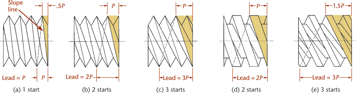
Multiple threads are used wherever quick motion, but not great power, is desired, as on ballpoint pens, toothpaste caps, valve stems, and so on. The threads on a valve stem are frequently multiple threads to impart quick action in opening and closing the valve. Multiple threads on a shaft can be recognized and counted by observing the number of thread starts on the end of the screw, as shown in Figure 13.11.

13.11 This shaded model of a triple-threaded bolt makes it easy to see the three distinct threads. When you look at the end view of a bolt, you can count the number of starts.
American National Thread Fits
For general use, three classes of fits between mating threads (as between bolt and nut) have been established by ANSI.
These fits are produced by the application of tolerances listed in the standard and are as follows:
Class 1 Fit Recommended only for screw thread work where clearance between mating parts is essential for rapid assembly and where shake or play is not objectionable.
Class 2 Fit Represents a high quality of commercial thread product and is recommended for the great bulk of interchangeable screw thread work.
Class 3 Fit Represents an exceptionally high quality of commercially threaded product and is recommended only in cases where the high cost of precision tools and continual checking are warranted.
The standard for unified screw threads specifies tolerances and allowances defining the several classes of fit (degree of looseness or tightness) between mating threads. In the symbols for fit, the letter A refers to the external threads and B to internal threads. There are three classes of fit each for external threads (1A, 2A, 3A) and internal threads (1B, 2B, 3B). Classes 1A and 1B have generous tolerances, facilitating rapid assembly and disassembly. Classes 2A and 2B are used in the normal production of screws, bolts, and nuts, as well as in a variety of general applications. Classes 3A and 3B provide for applications needing highly accurate and close-fitting threads.
Metric and Unified Thread Fits
Some specialized metric thread applications are specified by tolerance grade, tolerance position, class, and length of engagement. There are a number of tolerance grades for metric thread fits. These are based on the diameter of the thread. The tolerance grade is given as a number and the position is given as a letter. Upper case letters are used for internal thread (like that on nuts) and lower case letters are used for external thread (like that on bolts).
Grade 6 is a medium tolerance. A number lower than 6 specifies a tighter, finer tolerance; a number larger than 6 indicates larger, coarser tolerances, which might be required for long lengths of thread engagement. A general-purpose application has a tolerance class of 6H for internal threads and a class of 6g for external threads. Metric thread tolerance classes of 6H/6g are generally assumed if not otherwise designated and are used in applications comparable to the 2A/2B inch classes of fits.
When a double designation is given, such as 5g6g, this indicates separate tolerance grades for the pitch diameter (given first, 5g) and the major diameter of the thread (given second, 6g), in this case external thread. A single-tolerance designation, such as 6H, indicates that both the tolerance grade and position for the pitch diameter and the minor diameter are the same (in this case internal thread) so it is listed only once.
The tolerance grade for the minor diameter and for the pitch diameter of internal thread may be 4, 5, 6, 7 or 8. The major diameter of external thread may be grade 4, 6, or 8 and the external pitch diameter may be grades 3 through 9.
The tolerance position is the range of the tolerance from the basic size of the thread profile. For internal thread, H has a zero fundamental deviation, and G has a positive fundamental deviation. External thread may be h (zero fundamental deviation), or e, f, or g, which all have negative fundamental deviations, meaning that the thread element will be smaller than the basic size, to assure it may be threaded into the hole.
Three Methods for Drawing Thread
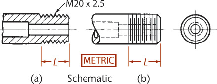
There are three methods of representing screw threads on drawings—the schematic, simplified, and detailed methods. All three types may be combined on a single drawing.
Schematic and the more common simplified representations are used to show threads. The symbols are the same for all forms of threads, such as metric, unified, square, and acme, but the thread specification identifies which is to be used.
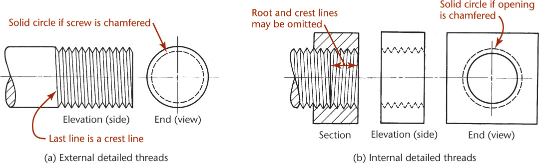
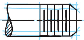
Detailed representation is a closer approximation of the exact appearance of a screw thread, in which the true profiles of the thread’s form are drawn; but the helical curves are replaced by straight lines. The true projection of the helical curves of a screw thread is rarely used in practice. Detailed representation is shown in Figure 13.12. Do not use detailed representation unless the diameter of the thread on the drawing is more than 1″ or 25 mm and then only to call attention to the thread when necessary. Whether the crests or roots are flat or rounded, they are represented by single lines and not double lines. American national and unified threads are drawn the same way. Figure 13.13 shows schematic thread symbols, and Figure 13.14 shows simplified thread symbols.

Detailed directions for drawing and sketching schematic and simplified thread are shown on pages 602 and 603.
![]() Draw the centerline and lay out the length and major diameter as shown at right.
Draw the centerline and lay out the length and major diameter as shown at right.
![]() Find the number of threads per inch in the Thread Table for American National and Unified threads. This number depends on the major diameter of the thread and whether the thread is internal or external.
Find the number of threads per inch in the Thread Table for American National and Unified threads. This number depends on the major diameter of the thread and whether the thread is internal or external.
Find the pitch (P) by dividing 1 by the number of threads per inch. For example, .75–10 UNC has a major diameter of .75 inches and is 10 threads per inch. The pitch for metric threads is given directly in the thread designation. For example, in the designation M20 × 2, the 20 mm diameter thread has a pitch of 2 mm.
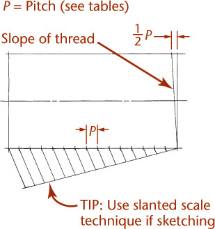
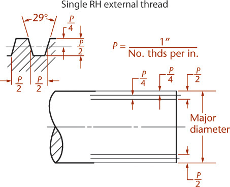
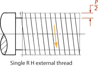
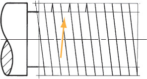
Establish the slope of the thread by offsetting the slope line .5P for single threads, P for double threads, 1.5P for triple threads, and so on. For righthand external threads, the slope slants upward to the left; for left-hand external threads, the slope slants upward to the right.
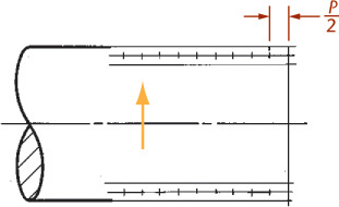
By eye, mark off even spacing for the pitch. If using CAD, make a single thread and array the lines using the pitch as the spacing.
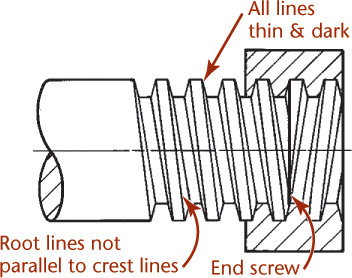
![]() From the pitch points, make crest lines parallel to the slope line. These should be dark, thin lines. Make two V’s to establish the depth of the thread, and sketch light guidelines for the root of the thread, as shown.
From the pitch points, make crest lines parallel to the slope line. These should be dark, thin lines. Make two V’s to establish the depth of the thread, and sketch light guidelines for the root of the thread, as shown.
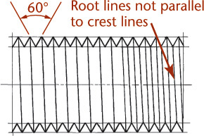
![]() Finish the final 60° V’s. The V’s should be vertical; they should not lean with the thread.
Finish the final 60° V’s. The V’s should be vertical; they should not lean with the thread.
Make root lines. Root lines will not be parallel to crest lines but should appear parallel to each other.
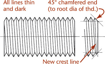
![]() When the end is chamfered (usually 45° with the end of the shaft, sometimes 30°), the chamfer extends to the thread depth. The chamfer creates a new crest line, which you make between the two new crest points. It is not parallel to the other crest lines. When finished, all thread root and crest lines should be shown thin, but dark.
When the end is chamfered (usually 45° with the end of the shaft, sometimes 30°), the chamfer extends to the thread depth. The chamfer creates a new crest line, which you make between the two new crest points. It is not parallel to the other crest lines. When finished, all thread root and crest lines should be shown thin, but dark.
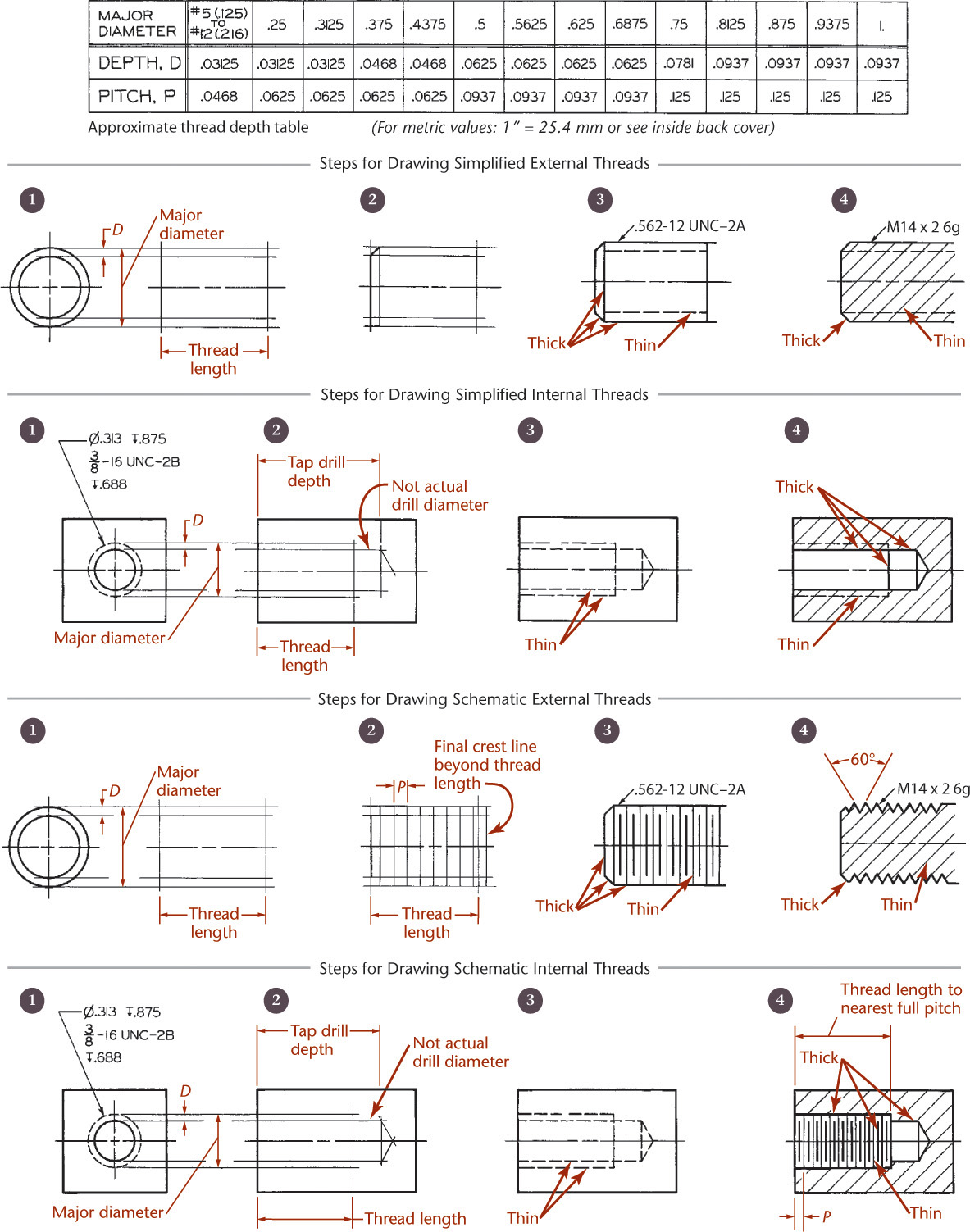
The thread depth table in Figure 13.15 gives approximate thread depths for a variety of common diameters. You can use thread depth tables to calculate the exact depth and spacing, but the calculated thread depth is often too small to show clearly on the drawing, so it is often shown larger than actual size for clarity.
Step by Step: Three Ways to Sketch Thread
Detailed Representation
Detailed representation is the most realistic looking, although it is a symbolic way of representing thread and does not show the helical shape accurately. Detailed representation is rarely ever sketched because it is time-consuming to draw the large number of lines making up its shape. Detailed representation does not reproduce well when the thread diameter on the sheet of paper is smaller than 1″ or 25 mm.
![]() Lightly block in the threaded shaft. Draw a light vertical line to define the threaded portion. Add lines angled at 45° to represent the chamfer.
Lightly block in the threaded shaft. Draw a light vertical line to define the threaded portion. Add lines angled at 45° to represent the chamfer.
![]() Make light ticks to mark the pitch distances.
Make light ticks to mark the pitch distances.

![]() Sketch 60° V’s representing the thread form.
Sketch 60° V’s representing the thread form.
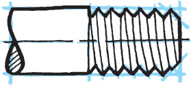
![]() Connect crest to crest and root to root and darken in the final lines.
Connect crest to crest and root to root and darken in the final lines.
Simplified Representation
Simplified representation uses hidden lines to represent the depth of the thread. Because the thread depth is different for different pitches or thread series, and can sometimes be quite small, this hidden line is often shown at 1/16″ or 2 mm so it can easily be identified on a sketched or printed drawing. Notice the lines that represent the chamfer and the end of the threaded length. The chamfer makes it easier to get the bolt started in the hole.
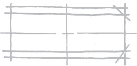
![]() Lightly block in the threaded shaft. Make a light vertical line to define the threaded portion. Use a light line to mark the thread depth.
Lightly block in the threaded shaft. Make a light vertical line to define the threaded portion. Use a light line to mark the thread depth.
![]() Sketch short dashes for the thread depth, then darken in the final lines.
Sketch short dashes for the thread depth, then darken in the final lines.
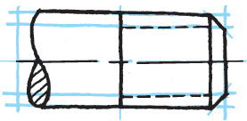
Schematic Thread Representation
Schematic thread representation uses shorter thick parallel lines to represent the roots of the thread and longer thin lines to represent the crests. The ends of screws and bolts are shown chamfered, as they are in detailed and simplified representation. Distances from crest to crest or root to root are not always shown accurately; instead they are often shown about 1/8″ or 3 mm apart to give the appearance of thread.

![]() Lightly block in the threaded shaft. Make a light vertical line to define the threaded portion. Use a light line to mark the thread depth.
Lightly block in the threaded shaft. Make a light vertical line to define the threaded portion. Use a light line to mark the thread depth.
![]() Use short thick lines to represent the roots and long thin lines to represent the crests.
Use short thick lines to represent the roots and long thin lines to represent the crests.
13.1 Thread Notes
ASME/ANSI Y14.6, Screw Thread Representation, is a standard for representing, specifying, and dimensioning screw threads on drawings. Thread notes for metric, unified, and American national screw threads are shown in Figures 13.16 through 13.19. These same notes or symbols are used in correspondence, on shop and storeroom records, and in specifications for parts, taps, dies, tools, and gages.


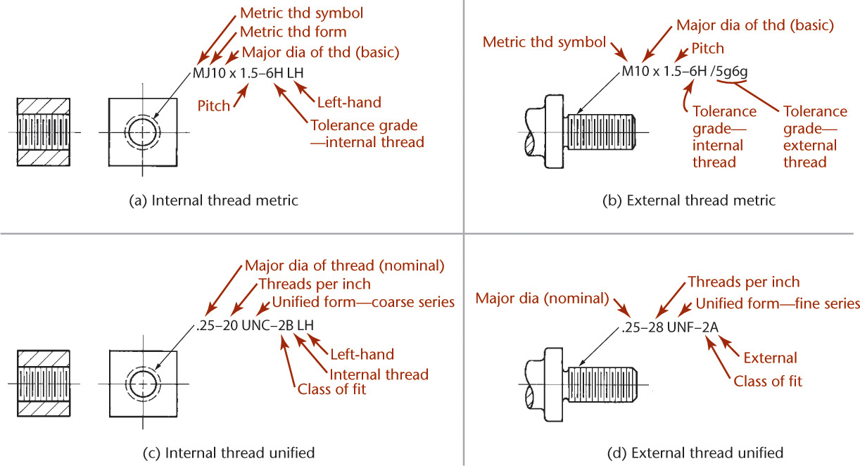
Metric screw threads are designated basically by the letter M (for metric thread) followed by the thread form and nominal size (basic major diameter) in millimeters and separated by the symbol × followed by the pitch, also in millimeters. For example, the basic thread note M10 × 1.5 is adequate for most commercial purposes, as shown in Figure 13.17. If needed, the class of fit and LH for left-hand designation is added to the note. (The absence of LH indicates a RH thread.)
If necessary, the length of the thread engagement is added to the thread note. The letter S stands for short, N means normal, and L means long. For example, the single note M10 × 1.5-6H/6g-N-LH combines the specifications for internal and external mating of left-hand metric threads of 10-mm diameter and 1.5-mm pitch with general-purpose tolerances and normal length of engagement.
For inch threads based on 60° forms, the thread designation should include (in order):
• Nominal diameter in inches
• Number of threads per inch
• Letter symbol of the thread series
• Number and letter of the thread class
• Any qualifying information needed, such as the class of fit or the thread gaging system
For example:
.750–16 UNF–2A(21)
A sample special thread designation is 1.50–7N-LH.
For multiple-start threads, use this format:
• Nominal diameter in inches
• Pitch in inches followed by the letter P
• Lead in inches followed by the letter L
• Number of starts in parentheses
• Letter symbol of the thread series
• Number and letter of the thread class
• Any qualifying information needed, such as the class of fit or the thread gaging system
For example:
.750–.0625P–.1875L (3 STARTS) UNF–2A(21)
Alternatively, the number of threads per inch can be given as is typical, followed by the lead in inches with the letter L afterward. Finally, the number of starts is given in parentheses, as in
.750–16–.1875L (3 STARTS) UNF–2A(21).
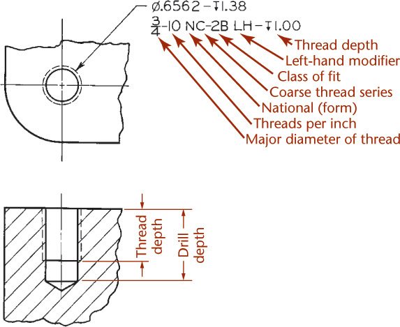
A thread note for a blind tapped hole is shown in Figure 13.16. A tap drill is sized to form a hole that will leave enough material for thread to be cut using a tap to form a threaded hole. In practice the tap drill size and depth are omitted and left up to the shop. At times it is desirable to state a tolerance range for the size of the hole prior to threading. This can be stated as follows:
∅.656–.658 BEFORE THD .75–20–NEF–2B
Thread notes for holes are preferably attached to the circular views of the holes. Thread notes for external threads are preferably given where the threaded shaft appears rectangular, as shown in Figures 13.18a–d.
When converting typical fractional nominal diameter sizes to decimals, the decimal equivalent for the major diameter is given to four decimal places (omitting zero in the fourth place). For example, .1375–32 UNF-2A
Thread notes for unified threads are shown in Figures 13.19c and d. The letters A and B designate external or internal, respectively, after the numeral designating the class of fit. If the letters LH are omitted, the thread is understood to be right hand.
The following are some typical thread notes:
9/16–18 UNF–2B
1.75–16 UN–2A
.25–.050P–.015L (3 STARTS) UNC–2A
Acme Thread Notes
ACME screw threads use the following two classes of fit:
G (general-purpose) Provides clearance on the major and minor diameters of the thread.
C (centralizing) Provides for contact of the major diameters.
For many applications either specification is adequate, but the centralizing fit is preferred when the load will be transverse to the screw axis, as the thread major diameters then act as radial bearings. The G designation is not to be confused with the G used for metric fits. Some typical thread notes are:
1.75–4 ACME–2G
1.75–6 ACME–4C
13.2 External Thread Symbols
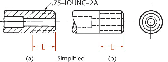
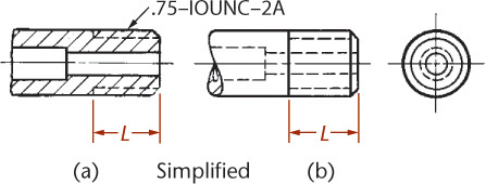
Simplified representations for external threads are shown in Figures 13.20a and b. The threaded portions are indicated by hidden lines parallel to the axis at the approximate depth of the thread, whether the cylinder appears rectangular or circular. The depth shown is not always the actual thread depth, just a representation of it. Use the table in Figure 13.15 for the general appearance of these lines.
When the schematic form is shown in section, as in Figure 13.21a, show the V’s of the thread to make the thread obvious. It is not necessary to show the V’s to scale or to the actual slope of the crest lines. To draw the V’s, use the schematic thread depth, as shown in Figure 13.16, and determine the pitch by drawing 60° V’s.
Schematic threads are indicated by alternating long and short lines, as shown in Figure 13.21b. The short lines representing the root lines are thicker than the long crest lines. Theoretically, the crest lines should be spaced according to actual pitch, but this would make them crowded and tedious to draw, defeating the purpose, which is to save time in sketching them. Space the crest lines carefully by eye, then add the heavy root lines halfway between the crest lines. Generally, lines closer together than about 1/16″ are hard to distinguish. The spacing should be proportionate for all diameters. You do not need to use these actual measurements in sketching schematic threads, just use them to get a feel for how far apart to make the lines.
13.3 Internal Thread Symbols
Internal thread symbols are shown in Figure 13.22. Note that the only differences between the schematic and simplified internal thread symbols occur in the sectional views. The representation of the internal schematic thread in section in Figures 13.22k, m, and o is exactly the same as the external representation shown in Figure 13.21b. Hidden threads, by either method, are represented by pairs of hidden lines. The hidden dashes should be staggered, as shown.
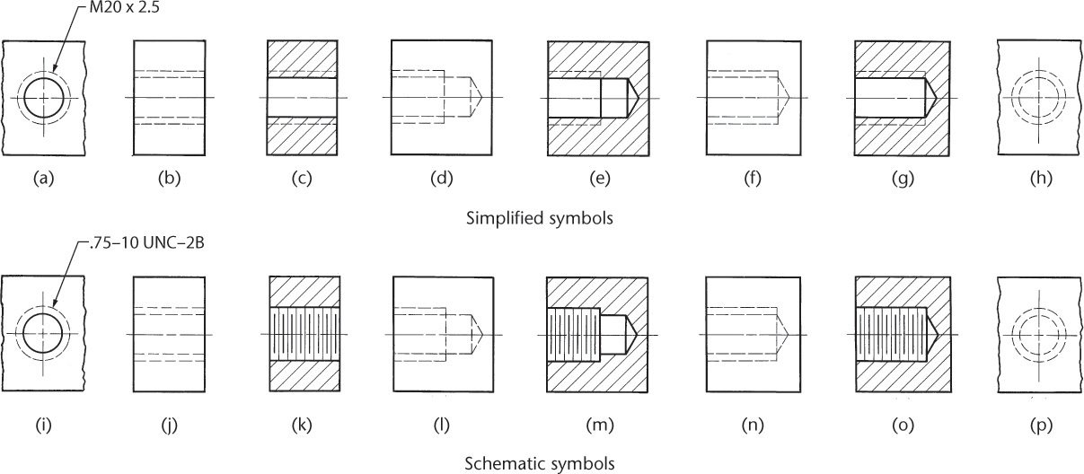
In the case of blind tapped holes, the drill depth normally is drawn at least three schematic pitches beyond the thread length, as shown in Figures 13.22d, e, l, and m. The symbols in Figures 13.22f and n represent the use of a bottoming tap, when the length of thread is the same as the depth of drill. The thread length you sketch may be slightly longer than the actual given thread length. If the tap drill depth is known or given, draw the drill to that depth. If the thread note omits this information, as is often done in practice, sketch the hole three schematic thread pitches beyond the thread length. The tap drill diameter is represented approximately, not to actual size.
Step by Step: Detailed Representation of Acme Threads
Detailed representation of acme threads is used only to call attention when details of the thread are important and the major diameter is larger than 1″ or 25 mm on the drawing. The steps are as follows.
![]() Make a centerline and lay out the length and major diameter of the thread, as shown. For U.S. drawings, determine the pitch by dividing 1 by the number of threads per inch (see Appendix 21). Make construction lines for the root diameter, making the thread depth P/2. Make construction lines halfway between crest and root guidelines.
Make a centerline and lay out the length and major diameter of the thread, as shown. For U.S. drawings, determine the pitch by dividing 1 by the number of threads per inch (see Appendix 21). Make construction lines for the root diameter, making the thread depth P/2. Make construction lines halfway between crest and root guidelines.
![]() Mark off spaces on the intermediate construction lines.
Mark off spaces on the intermediate construction lines.
![]() Through alternate points, make construction lines for the sides of the threads at 15° (instead of 14.5°).
Through alternate points, make construction lines for the sides of the threads at 15° (instead of 14.5°).

![]() Make construction lines for the other sides of the threads, as shown. For single and triple threads, a crest is opposite a root; for double and quadruple threads, a crest is opposite a crest. Finish tops and bottoms of threads.
Make construction lines for the other sides of the threads, as shown. For single and triple threads, a crest is opposite a root; for double and quadruple threads, a crest is opposite a crest. Finish tops and bottoms of threads.
![]() Make parallel crest lines.
Make parallel crest lines.
![]() Make parallel root lines, and finish the thread profiles. All lines should be thin and dark.
Make parallel root lines, and finish the thread profiles. All lines should be thin and dark.
The internal threads in the back of the nut and the external threads on the front side of the screw will slope in opposite directions.
End views of acme threaded shafts and holes are drawn exactly like those for the square thread.
13.4 Detailed Representation: Metric, Unified, and American National Threads
The detailed representation for metric, unified, and American national threads is the same, because the flats are disregarded.
Internal detailed threads in section are drawn as shown in Figure 13.23. Notice that for left-hand threads the lines slope upward to the left (Figures 13.23a–c); for right-hand threads the lines slope up to the right (Figures 13.23d–f).
Detailed Internal Square Thread
The internal thread construction is shown in Figure 13.24. Note that the thread lines representing the back half of the internal threads (because the thread is in section) slope in the opposite direction from those on the front side of the screw.
Steps in drawing a single internal square thread in section are shown in Figure 13.24. Note in Figure 13.24b that a crest is drawn opposite a root. This is the case for both single and triple threads. For double or quadruple threads, a crest is opposite a crest. Thus, the construction in Figures 13.24a and b is the same for any multiple of thread. The differences appear in Figure 13.24c, where the threads and spaces are distinguished and outlined.
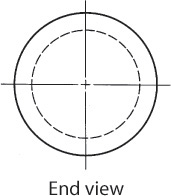
The same internal thread is shown in Figure 13.24e from an external view. The profiles of the threads are drawn in their normal position, but with hidden lines, and the sloping lines are omitted for simplicity. The end view of the same internal thread is shown in Figure 13.24f. Note that the hidden and solid circles are opposite those for the end view of the shaft.
Detailed External Square Thread
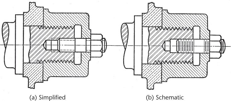
Figure 13.25 is an assembly drawing showing an external square thread partly screwed into a nut. When the external and internal threads are assembled, the thread in the nut overlaps and covers up half of the V, as shown at B.
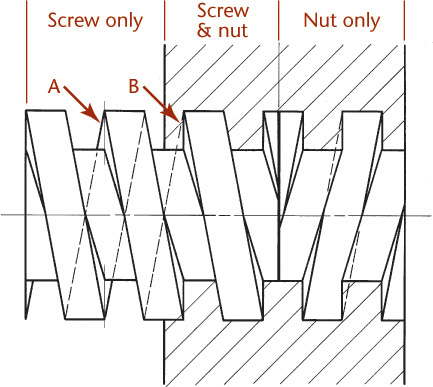
Sometimes in assemblies the root and crest lines may be omitted from the nut only portion of the drawing so that it is easier to identify the inserted screw.
Step by Step: Detailed Representation of Square Threads
Detailed representation of external square threads is used only when the major diameter is over about 1″ or 25 mm, and it is important to show the detail of the thread on the finished sketch or plotted drawing. The steps for creating a detailed square thread are as follows.
![]() Make a centerline and lay out the length and major diameter of the thread. For U.S. drawings, determine the pitch (P) by dividing 1 by the number of threads per inch. For a single right-hand thread, the lines slope upward to the left, and the slope line is offset as for all single threads of any form. On the upper line, use spacing equal to P/2, as shown.
Make a centerline and lay out the length and major diameter of the thread. For U.S. drawings, determine the pitch (P) by dividing 1 by the number of threads per inch. For a single right-hand thread, the lines slope upward to the left, and the slope line is offset as for all single threads of any form. On the upper line, use spacing equal to P/2, as shown.

![]() From the points on the upper line, draw guidelines for the root of the thread, making the depth as shown.
From the points on the upper line, draw guidelines for the root of the thread, making the depth as shown.
![]() Make parallel visible back edges of threads.
Make parallel visible back edges of threads.
![]() Make parallel visible root lines.
Make parallel visible root lines.

![]() All lines should be thin and dark.
All lines should be thin and dark.

Tip: End View of a Shaft
The end view of the shaft illustrated in this Step by Step feature is shown below. Note that the root circle is hidden. In a sketch, no attempt is made to show the true projection of any but the major diameter.
If the end of a shaft is chamfered, a solid circle is drawn instead of the hidden circle.
13.5 Threads in Assembly
Threads in an assembly drawing are shown in Figure 13.26. It is customary not to section a stud or a nut or any solid part unless necessary to show some internal shapes. Show these items “in the round,” as they would look if they were set in the hole after the assembly was cut to form the section. When external and internal threads are sectioned in assembly, the V’s are required to show the threaded connection.
13.6 Modeling Thread
Thread is not typically modeled, because this complex helical surface adds greatly to the complexity and file size of the model without providing much useful manufacturing information. Many 3D modeling packages allow you to model thread accurately, but it is better to include this type of information as a note, or if you require this level of detail in the model, wait to add it after you have worked out the major details of the design.
Sometimes, the major and minor diameters of the thread are represented so they can be used in checking clearances and interferences. If not, the nominal size (the general size used to identify the fastener) of the threaded hole or shaft is modeled. A detailed list of fasteners and their proportions is included in Appendices 17–19.
Sweep a Thread Form
Some modeling software allows you to define the helical path curve using an equation. Other software provides a helical sweep command that allows you to enter the number of revolutions and diameter parameters, which can be changed later.
To model thread:
a. Draw the cross-sectional shape of the thread.
b. Draw the helical path.
c. Sweep the cross section along the helical path to form the shape of the thread.

13.7 American National Standard Pipe Threads
The American National Standard for pipe threads, originally known as the Briggs standard, was formulated by Robert Briggs in 1882. Two general types of pipe threads have been approved as American National Standard: tapered and straight.
The profile of the tapered pipe thread is illustrated in Figure 13.27. The taper of the standard tapered pipe thread is 1 in 16, or .75″ per foot measured on the diameter and along the axis. The angle between the sides of the thread is 60°. The depth of the sharp V is .8660p, and the basic maximum depth of the thread is .800p, where p = pitch. The basic pitch diameters, E0 and E1, and the basic length of the effective external taper thread, L2, are determined by the formulas

13.27 American National Standard Taper Pipe Thread (Reprinted from ASME B1.20.1-1983 (R1992), by permission of The American Society of Mechanical Engineers. All rights reserved.)
E0 = D – (.050D + 1.1) 1/n
E1 = E0 + .0625L1
L2 = (.80D + 6.8) 1/n
where D = outer diameter of pipe, E0 = pitch diameter of thread at end of pipe, E1 = pitch diameter of thread at large end of internal thread, L1 = normal engagement by hand, and n = number of threads per inch.
ANSI also recommends two modified tapered pipe threads for (1) dry-seal pressure-tight joints (.880 per foot taper) and (2) rail fitting joints. The former is used for metal-to-metal joints, eliminating the need for a sealer, and is used in refrigeration, marine, automotive, aircraft, and ordnance work. The latter is used to provide a rigid mechanical thread joint as is required in rail fitting joints.
Although tapered pipe threads are recommended for general use, there are certain types of joints in which straight pipe threads are used to advantage. The number of threads per inch, the angle, and the depth of thread are the same as on the tapered pipe thread, but the threads are cut parallel to the axis. Straight pipe threads are used for pressure-tight joints for pipe couplings, fuel and oil line fittings, drain plugs, free-fitting mechanical joints for fixtures, loose-fitting mechanical joints for locknuts, and loose-fitting mechanical joints for hose couplings.
Pipe threads are represented by detailed or symbolic methods in a manner similar to that used to represent unified and American national threads. The symbolic representation (schematic or simplified) is recommended for general use regardless of the diameter, as shown in Figure 13.28. The detailed method is recommended only when the threads are large and when it is desired to show the profile of the thread, as for example, in a sectional view of an assembly.
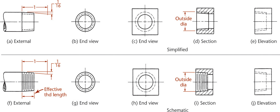
As shown in Figure 13.28, it is not necessary to draw the taper on the threads unless there is some reason to emphasize it, because the thread note indicates whether the thread is straight or tapered. If it is desired to show the taper, it is sometimes shown exaggerated to make it more visible, as shown in Figure 13.28, where the taper is drawn 1/16″ per 1″ on radius (or 0.75″ per 1′ on diameter) instead of the actual taper of 1/16″ on diameter. American National Standard tapered pipe threads are indicated by a note giving the nominal diameter followed by the letters NPT (national pipe taper), as shown in Figure 13.29. When straight pipe threads are specified, the letters NPS (national pipe straight) are used. In practice, the tap drill size is normally not given in the thread note.

13.8 Use of Phantom Lines
Use phantom lines to save time when representing identical features, as shown in Figure 13.30. Threaded shafts and springs may be shortened without using conventional breaks but must be correctly dimensioned.
13.9 Tapped Holes
The bottom of a drilled hole, formed by the point of a twist drill, is cone-shaped, as shown in Figures 13.31a and b. When an ordinary drill is used to make holes that will be tapped, it is referred to as a tap drill. When drawing the drill point, use an angle of 30° to approximate the actual 31° slope of the drill bit.
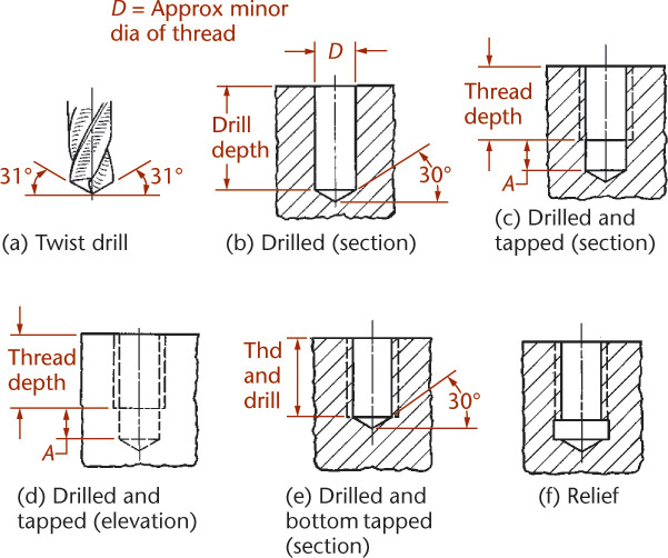
The thread length is the length of full or perfect threads. The tap drill depth does not include the cone point of the drill. In Figures 13.31c and d, the drill depth shown beyond the threads (labeled A) includes several imperfect threads produced by the chamfered end of the tap. This distance varies according to drill size and whether a plug tap or a bottoming tap is used to finish the hole.
A drawing of a tapped hole finished with a bottoming tap is shown in Figure 13.31e. Blind bottom-tapped holes are hard to form and should be avoided whenever possible. Instead, a relief with its diameter slightly greater than the major diameter of the thread is used, as shown in Figure 13.31f. Tap drill sizes for unified, American national, and metric threads can be found in tables. Tap drill sizes and lengths may be given in the thread note but are generally left to the manufacturer to determine. Because the tapped thread length contains only full threads, it is necessary to make this length only one or two pitches beyond the end of the engaging screw. In simplified or schematic representation, do not show threads in the bottoms of tapped holes. This way the ends of the screw show clearly.
The thread length in a tapped hole depends on the major diameter and the material being tapped. The minimum engagement length, when both parts are steel, is equal to the diameter (D) of the thread. Table 13.2 shows different engagement lengths for different materials.
Tip
Prevent tap breakage: A chief cause of tap breakage is insufficient tap drill depth. When the depth is too short, the tap is forced against a bed of chips in the bottom of the hole. Don’t specify a blind hole when a through hole of not much greater length can be used. When a blind hole is necessary, the tap drill depth should be generous.
Clearance holes: When a bolt or a screw passes through a clearance hole, the hole is often drilled 0.8 mm larger than the screw for screws of 3/8″ (10 mm) diameter and 1.5 mm larger for larger diameters. For more precise work, the clearance hole may be only 1/64″ (0.4 mm) larger than the screw for diameters up to 10 mm and 0.8 mm larger for larger diameters.
Closer fits may be specified for special conditions. The clearance spaces on each side of a screw or bolt need not be shown on a drawing unless it is necessary to show clearly that there is no thread engagement. When it is necessary to show that there is no thread engagement, the clearance spaces should be drawn about 3/64″ (1.2 mm) wide.
13.10 Bolts, Studs, and Screws
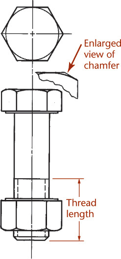
The term bolt is generally used to denote a “through bolt” that has a head on one end, is passed through clearance holes in two or more aligned parts, and is threaded on the other end to receive a nut to tighten and hold the parts together, as shown in Figure 13.33a. A hexagon head cap screw, shown in Figure 13.33b, is similar to a bolt except it often has greater threaded length. It is often used when one of the parts being held together is threaded to act as a nut. The cap screw is screwed on with a wrench. Cap screws are not screwed into thin materials if strength is desired.
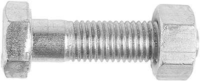

A stud, shown in Figure 13.33c, is a steel rod threaded on one or both ends. If threaded on both ends, it is screwed into place with a pipe wrench or with a stud driver. If threaded on one end, it is force-fitted into place. As a rule, a stud is passed through a clearance hole in one member, is screwed into another member, and uses a nut on the free end, as shown in Figure 13.33c.
A machine screw is similar to a slotted head cap screw but usually smaller. It may be used with or without a nut. Figure 13.34 shows different screw head types.

A set screw is a screw, with or without a head, that is screwed through one member and whose special point is forced against another member to prevent motion between the two parts.

(Courtesy of Michael Goldman/Taxi/Getty Images.)
Do not section bolts, nuts, screws, and similar parts when drawn in assembly because they do not have interior detail that needs to be shown.
13.11 Standard Bolts and Nuts
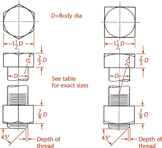
American National Standard hexagon bolts and nuts are made in both metric and inch sizes. Square bolts and nuts, shown in Figure 13.35c, are produced only in inch sizes. Square heads and nuts are chamfered at 30°, and hexagon heads and nuts are chamfered at 15°–30°. Both are drawn at 30° for simplicity. Metric bolts, cap screws, and nuts also come in hexagon form.

Bolt Types Bolts are grouped into bolt types according to use: regular bolts for general use and heavy bolts for heavier use or easier wrenching. Square bolts come only in the regular type; hexagon bolts, screws, nuts, and square nuts are available in both regular and heavy.
Metric hexagon bolts are grouped according to use: regular and heavy bolts and nuts for general service and high-strength bolts and nuts for structural bolting.
Finish Square bolts and nuts, hexagon bolts, and hexagon flat nuts are unfinished. Unfinished bolts and nuts are not machined on any surface except for the threads. Hexagon cap screws, heavy hexagon screws, and all hexagon nuts, except hexagon flat nuts, are considered finished to some degree and have a “washer face” machined or otherwise formed on the bearing surface. The washer face is 1/64″ thick (drawn 1/32″ so that it will be visible on the plotted drawing), and its diameter is 1.5 times the body diameter for the inch series.
For nuts, the bearing surface may also be a circular surface produced by chamfering. Hexagon screws and hexagon nuts have closer tolerances and a more finished appearance but are not completely machined. There is no difference in the drawing for the degree of finish on finished screws and nuts.
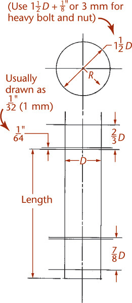
Proportions Proportions for both inch and metric are based on the diameter (D) of the bolt body. These are shown in Figure 13.35.
For regular hexagon and square bolts and nuts, proportions are
where W = width across flats, H = head height, and T = nut height.
For heavy hexagon bolts and nuts and square nuts, the proportions are
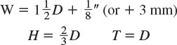
The washer face is always included in the head or nut height for finished hexagon screw heads and nuts.
Threads Square and hex bolts, hex cap screws, and finished nuts in the inch series are usually Class 2 and may have coarse, fine, or 8-pitch threads. Unfinished nuts have coarse threads and are Class 2B. For diameter and pitch specifications for metric threads, see Appendix 17.
Thread lengths For bolts or screws up to 6″ (150 mm) long,
For bolts or screws over 6″ in length,
Fasteners too short for these formulas are threaded as close to the head as practical. For drawing purposes, use approximately three pitches. The threaded end may be rounded or chamfered, but it is usually drawn with a 45° chamfer from the thread depth, as shown in Figure 13.35.
Bolt Lengths Bolt lengths have not been standardized because of the endless variety required by industry. Short bolts are typically available in standard length increments of 1/4″ (6 mm), and long bolts come in increments of 1/2″ to 1″ (12 to 25 mm). For dimensions of standard bolts and nuts, see Appendix 17.
13.12 Drawing Standard Bolts
Detail drawings show all the necessary information defining the shape, size, material, and finish of a part. Standard bolts and nuts do not usually require detail drawings unless they are to be altered (for example, by having a slot added through the end of a bolt), because they are usually stock parts that can easily be purchased, but you often need to show them on assembly drawings, which you will learn more about in Chapter 14.
Templates are available to help you add bolts quickly to sketches, or you can use the dimensions from tables if accuracy is important, as in figuring clearances. In most cases, a quick representation, where proportions are based on the body diameter, is sufficient. Three typical bolts illustrating the use of these proportions are shown in Figure 13.35.
Many CAD systems have fastener libraries that you can use to add a wide variety of nuts and bolts to your drawings. Often, these symbols are based on a diameter of 1 unit so that you can quickly figure a scale at which to insert them. Other systems prompt for the diameter and lengths and create a symbol to your specifications. In 3D models, when nuts and bolts are represented, the thread is rarely shown because it adds to the complexity and size of the drawing and is difficult to model. The thread specification is annotated in the drawing.
Generally, bolt heads and nuts should be drawn “across corners” in all views, regardless of projection. This conventional violation of projection is used to prevent confusion between the square and hexagon heads and nuts and to show actual clearances. Only when there is a special reason should bolt heads and nuts be drawn across flats, as shown in Figure 13.36.
13.13 Specifications for Bolts and Nuts
In specifying bolts in parts lists, in correspondence, or elsewhere, the following information must be covered in order:
1. Nominal size of bolt body
2. Thread specification or thread note
3. Length of bolt
4. Finish of bolt
5. Style of head
6. Name
Example (complete decimal inch)
.75–10 UNC–2A × 2.5 STAINLESS STEEL HEXAGON CAP SCREW
Example (abbreviated decimal inch)
.75–10 UNC × 2.5 SS HEXCAP SCR
Example (metric)
M14–2 × 20 SS HEXCAP SCR
For either bolts or nuts, REGULAR or GENERAL PURPOSE are assumed if omitted from the specification. If the heavy series is intended, the word HEAVY should appear as the first word in the name of the fastener. Likewise, HIGH STRENGTH STRUCTURAL should be indicated for such metric fasteners and the particular grade may be specified. However, the number of the specific ISO standard is often included in the metric specifications—for example, M20–2.5 DIN 934 HEX NUT. Finish need not be mentioned if the fastener or nut is correctly named.
Nuts may be specified as follows:
Example (complete)
![]()
Example (abbreviated)
![]()
Example (metric)
M20–2.5 HEX NUT
Step by Step: Sketching Hex Bolts, Cap Screws, and Nuts
![]() Determine the diameter of the bolt, the length (from the underside of the bearing surface to the tip), the style of head (square or hexagon), the type (regular or heavy), and the finish before starting to draw.
Determine the diameter of the bolt, the length (from the underside of the bearing surface to the tip), the style of head (square or hexagon), the type (regular or heavy), and the finish before starting to draw.
![]() Lightly sketch the top view as shown, where D is the diameter of the bolt. Project the corners of the hexagon or square to the front view. Sketch the head and nut heights. Add the washer face if needed. Its diameter is equal to the distance across flats of the bolt head or nut. Only the metric and finished hexagon screws or nuts have a washer face. The washer face is 1/64″ (0.4 mm) thick but is shown at about 1/32″ (1 mm) for clarity. The head or nut height includes the washer face.
Lightly sketch the top view as shown, where D is the diameter of the bolt. Project the corners of the hexagon or square to the front view. Sketch the head and nut heights. Add the washer face if needed. Its diameter is equal to the distance across flats of the bolt head or nut. Only the metric and finished hexagon screws or nuts have a washer face. The washer face is 1/64″ (0.4 mm) thick but is shown at about 1/32″ (1 mm) for clarity. The head or nut height includes the washer face.

![]() Represent the curves produced by the chamfer on the bolt heads and nuts as circular arcs, although they are actually hyperbolas. On drawings of small bolts or nuts under approximately 1/2″ (12 mm) in diameter, where the chamfer is hardly noticeable, omit the chamfer in the rectangular view.
Represent the curves produced by the chamfer on the bolt heads and nuts as circular arcs, although they are actually hyperbolas. On drawings of small bolts or nuts under approximately 1/2″ (12 mm) in diameter, where the chamfer is hardly noticeable, omit the chamfer in the rectangular view.

![]() Chamfer the threaded end of the screw at 45° from the thread depth.
Chamfer the threaded end of the screw at 45° from the thread depth.

![]() Show threads in simplified or schematic form for diameters of 1″ (25 mm) or less on the drawing. Detailed representation is rarely used because it clutters the drawing and takes too much time.
Show threads in simplified or schematic form for diameters of 1″ (25 mm) or less on the drawing. Detailed representation is rarely used because it clutters the drawing and takes too much time.
Hex head bolts come in a variety of SAE grades. A system of marks on the head of the bolt indicates the grade, which is an indication of its minimum tensile strength.
The commonly used grades are 1 or 2 which are unmarked and are low to medium carbon steel. Grade 5 bolts provide higher minimum tensile strength. They are marked with 3 lines on the bolt head. Grade 8 bolts provide even higher minimum tensile strength and are marked with 6 lines.
Metric grades are marked with numerals in the format X.Y indicating the various grades, for example, 4.6 is a low carbon steel metric grade.
Bolt selection and the torques required to tighten them are based on your particular application.
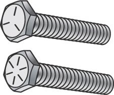
SAE grade 8 has 6 lines marked on the bolt head; SAE grade 5 has 3 lines marked on the bolt head.
13.14 Locknuts and Locking Devices
Many types of special nuts and devices to prevent nuts from unscrewing are available, and some of the most common are shown in Figure 13.37. The American National Standard jam nuts, as shown in Figures 13.37a and 13.37b, are the same as the hexagon or hexagon flat nuts, except that they are thinner. The application shown in Figure 13.37b, where the larger nut is on top and is screwed on more tightly, is recommended. They are the same distance across flats as the corresponding hexagon nuts (1-1/2D or 1″). They are slightly more than 1/2D in thickness but are drawn 1/2D for simplicity. They are available with or without the washer face in the regular and heavy types. The tops of all are flat and chamfered at 30°, and the finished forms have either a washer face or a chamfered bearing surface.
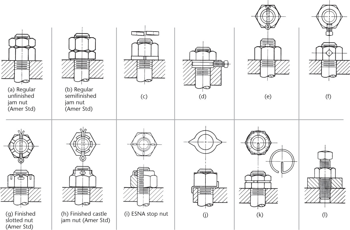
The lock washer, shown in Figure 13.37c, and the cotter pin, shown in Figure 13.37e, are very common (see Appendices 26 and 29). The set screw, shown in Figure 13.37f, is often made to press against a plug of softer material, such as brass, which in turn presses against the threads without deforming them. With cotter pins (see Appendix 29), it is recommended to use a hex slotted nut (Figure 13.37g), a hex castle nut (Figure 13.37h), or a hex thick slotted nut or a heavy hex thick slotted nut.
Similar metric locknuts and locking devices are available. See fastener catalogs for details.
Hexagon Head Screws Coarse, fine, or 8-thread series, 2A. Thread length = ![]() ″ up to 6″ long and
″ up to 6″ long and ![]() ″ if over 6″ long. For screws too short for formula, threads extend to within
″ if over 6″ long. For screws too short for formula, threads extend to within ![]() threads of the head for diameters up to 1″. Screw lengths not standardized. For suggested lengths for metric hexagon head screws, see Appendix 17.
threads of the head for diameters up to 1″. Screw lengths not standardized. For suggested lengths for metric hexagon head screws, see Appendix 17.
Slotted Head Screws Coarse, fine, or 8-thread series, 2A. Thread length = ![]() ″. Screw lengths not standardized. For screws too short for formula, threads extend to within
″. Screw lengths not standardized. For screws too short for formula, threads extend to within ![]() threads of the head.
threads of the head.
Hexagon Socket Screws Coarse or fine threads, 3A. Coarse thread length = ![]() ″ where this would be over
″ where this would be over ![]() ; otherwise thread length =
; otherwise thread length = ![]() . Fine thread length =
. Fine thread length = ![]() ″ where this would be over
″ where this would be over ![]() ; otherwise thread length =
; otherwise thread length = ![]() . Increments in screw lengths =
. Increments in screw lengths = ![]() ″ for screws
″ for screws ![]() ″ to 1″ long,
″ to 1″ long, ![]() ″ for screws 1″ to 3″ long, and
″ for screws 1″ to 3″ long, and ![]() ″ for screws
″ for screws ![]() ″ to 6″ long.
″ to 6″ long.
13.15 Standard Cap Screws
Five types of American National Standard cap screws are shown in Figure 13.38. The first four of these have standard heads, whereas the socket head cap screws, as shown in Figure 13.38e, have several different shapes of round heads and sockets. Cap screws are normally finished and are used on machine tools and other machines when accuracy and appearance are important. The ranges of sizes and exact dimensions are given in Appendices 17 and 18. The hexagon head cap screw and hex socket head cap screw are also available in metric.
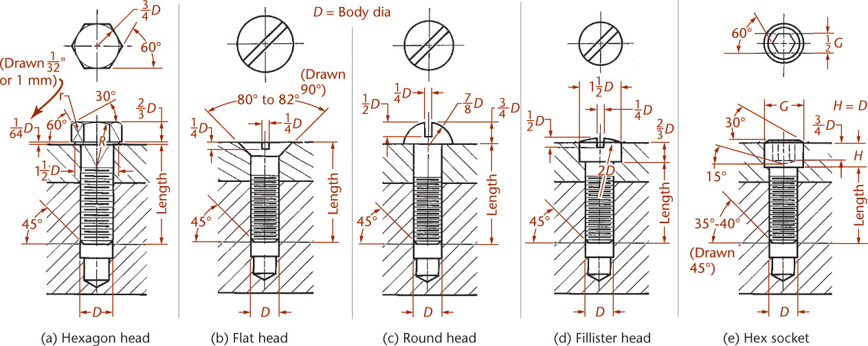
13.38 Standard Cap Screws—See Appendices 17 and 18
Cap screws ordinarily pass through a clearance hole in one member and screw into another.
Cap screws are inferior to studs when frequent removal is necessary. They are used on machines requiring few adjustments. The slotted or socket-type heads are used for crowded conditions.
Actual dimensions may be used in drawing cap screws when exact sizes are necessary. Figure 13.38 shows the proportions in terms of body diameter (D) that are usually used. Hexagonal head cap screws are drawn similar to hex head bolts. The points are chamfered at 45° from the schematic thread depth.
Note that screwdriver slots are drawn at 45° in the circular views of the heads, without regard to true projection, and that threads in the bottom of the tapped holes are omitted so that the ends of the screws may be clearly seen. A typical cap screw note is
Example (complete)
.375–16 UNC-2A × 2.5 HEXAGON HEAD CAP SCREW
Example (abbreviated)
.375 × 2.5 HEX HD CAP SCR
Example (metric)
M20 × 2.5 × 80 HEX HD CAP SCR
13.16 Standard Machine Screws
Machine screws are similar to cap screws but are usually smaller (.060″ to .750″ diameter) and the threads generally go all the way to the head. There are eight ANSI-approved forms of heads, which are shown in Appendix 19. The hexagonal head may be slotted if desired. All others are available in either slotted- or recessed-head forms. Standard machine screws are produced with a naturally bright finish, not heat treated, and have plain-sheared ends, not chamfered. For similar metric machine screw forms and specifications, see Appendix 19.
Machine screws are used for screwing into thin materials, and the smaller-numbered screws are threaded nearly to the head. They are used extensively in firearms, jigs, fixtures, and dies. Machine screw nuts are used mainly on the round head, pan head, and flat head types and are usually hexagonal.
Exact dimensions of machine screws are given in Appendix 19 tables, but they are seldom needed for drawing purposes. The four most common types of machine screws are shown in Figure 13.39, with proportions based on the diameter (D). Clearance holes and counterbores should be made slightly larger than the screws.
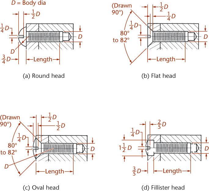
13.39 Standard Machine Screws—See Appendix 19
Typical machine screw notes are:
Example (complete)
![]()
Example (abbreviated)
![]()
Example (metric)
Spotlight: Screw Drive Types
Slotted Easily manufactured, this common drive type is often called a flat head screw.
Phillips Named for Henry F. Phillips, though he is not credited with inventing it, but rather with the refined design and manufacture. This head type is designed to be self centering and to limit overtightening.
Pozidriv Pozidriv screws are similar to Phillips but they allow you to apply more torque than the Phillips design does. SupaDriv is a similar style.
Hex Hex (or Allen key) heads are easy to produce and insert with low cost hex-key tools.
Hexalobular Often called torx head or star because of the 6 point star pattern, these styles provide better contact between the driver and the screw head to allow higher torque. TTAP is an improved design to reduce wobble.
Security T Similar to a torx screw, but designed to be even more difficult to remove without the proper tool.
Double-square This head style has an 8-pointed star shape. It can be driven with a square drive, but has more positions for easier insertion of the tool.
Japanese Industrial Standard (JIS) Sometimes called Japanese Phillips, these cross-style heads have a single depressed dot or an “X” to one side of the cross slot to indicate that they can be overtightened with a Phillips screwdriver.
Combinations Some screws accept more than one style of driver, such as the slottedPhillips. Slotted-pozidriv heads are also common in electrical products.
Many other specialty drive types are available for security, single direction turning, limited reuse, special torque requirements, and other factors. Special drivers are also available to allow precise torquing of screws.
13.17 Standard Set Screws
Set screws, shown in Figure 13.40, are used to prevent motion, usually rotary, between two parts, such as the movement of the hub of a pulley on a shaft. A set screw is screwed into one part so that its point bears firmly against another part. If the point of the set screw is cupped, or if a flat is milled on the shaft, the screw will hold much more firmly. Obviously, set screws are not efficient when the load is heavy or when it is suddenly applied. Usually they are manufactured of steel and case hardened (Figure 13.41).
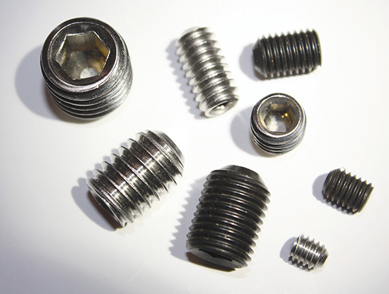
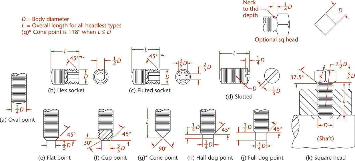
Headless set screws have come into greater use because a projecting head on a set screw has caused many industrial casualties; this has resulted in legislation prohibiting their use in many states.
Metric hexagon socket headless set screws with the full range of points are available. Nominal diameters of metric hex socket set screws are 1.6, 2, 2.5, 3, 4, 5, 6, 8, 10, 12, 16, 20, and 24 mm.
Square-head set screws have coarse, fine, or 8-pitch threads and are Class 2A but are usually furnished with coarse threads, because the square-head set screw is generally used on the rougher grades of work. Slotted headless and socket set screws have coarse or fine threads and are Class 3A.
Nominal diameters of set screws range from number 0 up through 2″. Set screw lengths are standardized in increments of 1/32″ to 1″ depending on the overall length of the set screw.
Metric set screw length increments range from 0.5 to 4 mm, again depending on overall screw length.
Set screws are specified as follows:
Example (complete)
.375–16UNC-2A × .75 SQUARE HEAD FLAT POINT SET SCREW
Example (abbreviated)
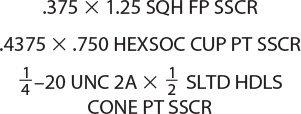
Example (metric)
M10–1.5 × 12 HEX SOCKET HEAD SET SCREW
13.18 American National Standard Wood Screws
Wood screws with three types of heads—flat, round, and oval—have been standardized. The approximate dimensions sufficient for drawing purposes are shown in Figure 13.42.

Wood Screws (Courtesy of Michael Newman/PhotoEdit Inc.)
The Phillips style recessed head is also available on several types of fasteners, as well as on wood screws. Three styles of cross recesses have been standardized by ANSI. A special screwdriver is used, as shown in Figure 13.43q, and this results in rapid assembly without damage to the head.
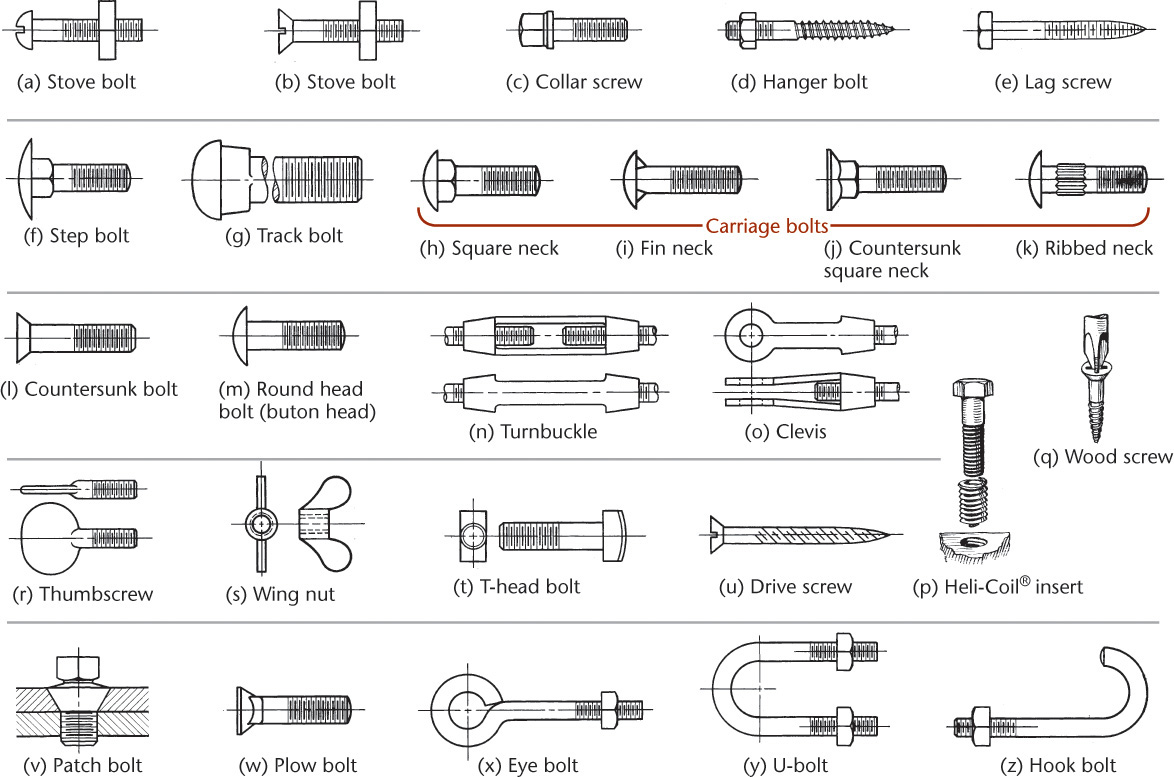
13.19 Miscellaneous Fasteners
Many other types of fasteners have been devised for specialized uses. Some of the more common types are shown in Figure 13.43. A number of these are American National Standard round head bolts, including carriage, button head, step, and countersunk bolts.
Helical-coil-threaded inserts, shown in Figure 13.43p, are shaped like a spring except that the cross section of the wire conforms to threads on the screw and in the hole. These are made of phosphor bronze or stainless steel, and they provide a hard, smooth protective lining for tapped threads in soft metals and plastics.
13.20 Keys
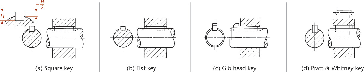
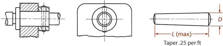
Keys are used to prevent movement between shafts and wheels, couplings, cranks, and similar machine parts attached to or supported by shafts, as shown in Figure 13.44. A keyseat is in a shaft; a keyway is in the hub or surrounding part.
For heavy-duty functions, rectangular keys (flat or square) are used, and sometimes two rectangular keys are necessary for one connection. For even stronger connections, interlocking splines may be machined on the shaft and in the hole.
A square key is shown in Figure 13.44a.
A flat key is shown in Figure 13.44b. The widths of keys are generally about one fourth the shaft diameter. In either case, half the key is sunk into the shaft. The depth of the keyway or the keyseat is measured on the side—not the center—as shown in Figure 13.44a. Square and flat keys may have the top surface tapered 1/8″ per foot, in which case they become square taper or flat taper keys.
A feather key is rectangular to prevent rotary motion, but permits relative longitudinal motion. Usually, feather keys have gib heads, or are fastened so they cannot slip out of the keyway.
A gib head key (Figure 13.44c) is the same as a square taper or flat taper key except that a gib head allows its easy removal. Square and flat keys are made from cold-finished stock and are not machined. For dimensions, see Appendix 20.
A Pratt & Whitney key (P&W key) is shown in Figure 13.44d. It is rectangular, with semicylindrical ends. Two-thirds of its height is sunk into the shaft keyseat (see Appendix 24).
Woodruff keys are semicircular, as shown in Figure 13.45. This key fits into a semicircular key slot cut with a Woodruff cutter, as shown, and the top of the key fits into a plain rectangular keyway. Sizes of keys for given shaft diameters are not standardized. For average conditions, select a key whose diameter is approximately equal to the shaft diameter. For dimensions, see Appendix 23. See manufacturers’ catalogs for specifications for metric counterparts.

Typical specifications for keys are
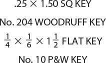
13.21 Machine Pins
Machine pins include taper pins, straight pins, dowel pins, clevis pins, and cotter pins. For light work, taper pins can be used to fasten hubs or collars to shafts. Figure 13.46 shows the use of a taper pin where the hole through the collar and shaft is drilled and reamed when the parts are assembled. For slightly heavier duty, a taper pin may be used parallel to the shaft, as for square keys (see Appendix 28).
Dowel pins are cylindrical or conical and usually used to keep two parts in a fixed position or to preserve alignment. They are usually used where accurate alignment is essential. Dowel pins are generally made of steel and are hardened and ground in a centerless grinder.
Clevis pins are used in a clevis and held in place by cotter pins. For the latter, see Appendix 29.
13.22 Rivets
Rivets are regarded as permanent fastenings, unlike removable fastenings, such as bolts and screws. Rivets are generally used to hold sheet metal or rolled steel together and are made of wrought iron, carbon steel, copper, or occasionally other metals.
To fasten two pieces of metal together, holes are punched, drilled, or punched and then reamed, all slightly larger in diameter than the shank of the rivet. Rivet diameters are made from ![]() to
to ![]() , where d is the rivet diameter and t is the metal thickness. The larger rivet diameter size is used for steel and single-riveted joints, and the smaller may be used for multiple-riveted joints. In structural work it is common to make the hole 1.6 mm (1/16″) larger than the rivet.
, where d is the rivet diameter and t is the metal thickness. The larger rivet diameter size is used for steel and single-riveted joints, and the smaller may be used for multiple-riveted joints. In structural work it is common to make the hole 1.6 mm (1/16″) larger than the rivet.
When the red-hot rivet is inserted, a “dolly bar” with a depression the shape of the driven head is held against the head. A riveting machine is used to drive the rivet and forms the head on the plain end. This causes the rivet to swell and fill the hole tightly.
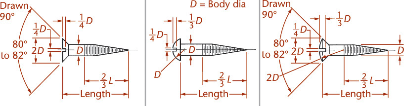
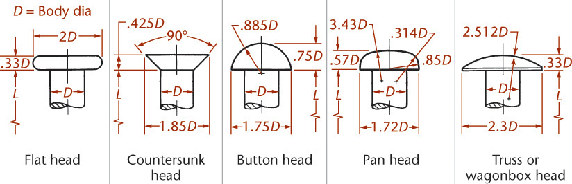
Large rivets or heavy hex structural bolts are often used in structural work for bridges and buildings and in ship and boiler construction. They are shown in Figure 13.47 in their exact formula proportions. Button heads (Figure 13.47a) and countersunk heads (Figure 13.47e) are the rivets most commonly used in structural work. The button head and cone head are commonly used in tank and boiler construction.

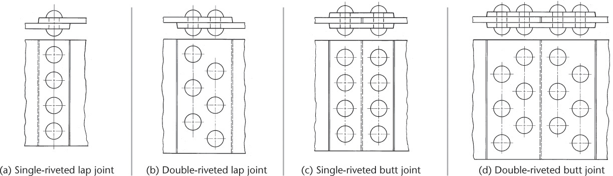
Riveted Joints
Typical riveted joints are shown in Figure 13.48. Note that the rectangular view of each rivet shows the shank of the rivet with both heads made with circular arcs, and the circular view of each rivet is represented by only the outside circle of the head.
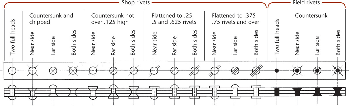
Rivet Symbols
Because many engineering structures are too large to be built in the shop, they are built in the largest units possible and then are transported to the desired location. Trusses are common examples. The rivets driven in the shop are called shop rivets, and those driven on the job are called field rivets. However, heavy steel bolts are commonly used on the job for structural work. Solid black circles are used to represent field rivets, and other standard symbols are used to show other features, as shown in Figure 13.49.
Small Rivets
Small rivets are used for light work. American National Standard small solid rivets are illustrated with dimensions that show their standard proportions in Figure 13.50, from ANSI/ASME B18.1.1. Included in the same standard are tinners’, coppers’, and belt rivets. Metric rivets are also available. Dimensions for large rivets are in ANSI/ASME B18.1.2. See manufacturers’ catalogs for additional details.
Blind Rivets
Blind rivets, commonly known as pop rivets (Figure 13.51), are often used for fastening together thin sheet-metal assemblies. Blind rivets are hollow and are installed with manual or power-operated rivet guns that grip a center pin or mandrel, pulling the head into the body and expanding the rivet against the sheet metal. They are available in aluminum, steel, stainless steel, and plastic. As with any fastener, it is important to choose an appropriate material to avoid corrosive action between dissimilar metals.

13.23 Springs
A spring is a mechanical device designed to store energy when deflected and to return the equivalent amount of energy when released (see ANSI Y14.13M). Springs are commonly made of spring steel, which may be music wire, hard-drawn wire, or oil-tempered wire. Other materials used for compression springs include stainless steel, beryllium copper, and phosphor bronze. Urethane plastic is used in applications where conventional springs would be affected by corrosion, vibration, or acoustic or magnetic forces.
Springs are classified as helical springs (Figure 13.52), or flat springs.

Helical Springs
Helical springs are usually cylindrical but may also be conical. There are three types of helical springs:
• Compression springs offer resistance to a compressive force.
• Extension springs offer resistance to a pulling force.
• Torsion springs offer resistance to a torque or twisting force.

Springs (Norton, Robert L., Machine Design: An Integrated Approach, 3rd, © 2006. Printed and electronically reproduced by permission of Pearson Education, Upper Saddle River, NJ.)
On working drawings, true projections of helical springs are not drawn because of the labor involved. Like screw threads, they are drawn in detailed and schematic methods, using straight lines to replace helical curves, as shown in Figure 13.52.
A square wire spring is similar to the square thread with the core of the shaft removed, as in Figure 13.52b. Use standard cross-hatching if the areas in section are large, as in Figures 13.52a and b. Small sectioned areas may be made solid black, as in Figure 13.52c.
In cases where a complete picture of the spring is not necessary, use phantom lines to save time in drawing the coils, as in Figure 13.52d. If the drawing of the spring is too small to be represented by the outlines of the wire, use schematic representation, shown in Figures 13.52e and f.
Compression springs have plain ends, as in Figure 13.53a, or squared (closed) ends, as in Figure 13.53b. The ends may be ground, as shown in Figure 13.53c, or both squared and ground, as in Figure 13.53d. Required dimensions are indicated in the figure. When required, RH or LH is specified for right-hand or left-hand coil direction.
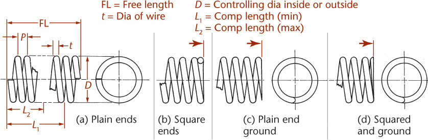
Extension springs may have many types of ends, so it is necessary to draw the spring or at least the ends and a few adjacent coils, as shown in Figure 13.54.
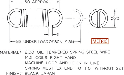
A typical torsion spring drawing is shown in Figure 13.55. A typical flat spring drawing is shown in Figure 13.56. Other types of flat springs are power springs (or flat coil springs), Belleville springs (like spring washers), and leaf springs (commonly used in automobiles).

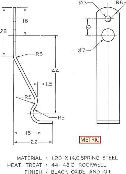
Many companies use a printed specification form to provide the necessary spring information, including data such as load at a specified deflected length, load rate, finish, and type of service.
13.24 Drawing Helical Springs
The construction for a schematic elevation view of a compression spring with six total coils is shown in Figure 13.57a. Because the ends are closed, or squared, two of the six coils are “dead” coils, leaving only four full pitches to be set off along the top of the spring.
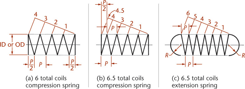
If there are six and a half total coils, as shown in Figure 13.57b, the P/2 measurement is set on opposite sides of the spring. The construction of an extension spring with six active coils and loop ends is shown in Figure 13.57c.
Figure 13.58 shows the steps in drawing a detailed section and elevation view of a compression spring. The spring is shown pictorially in Figure 13.58a. Figure 13.58b shows the cutting plane through the centerline of the spring. Figure 13.58c shows the section with the cutting plane removed. Steps to construct the sectional view are shown in Figures 13.58d–f. Figure 13.58g shows the corresponding elevation view.

If there are a fractional number of coils, such as the 5.5 coils in Figure 13.58h, the half-rounds of sectional wire are placed on opposite sides of the spring.
13.25 Modeling Springs
Using 3D modeling, it is uncommon to model springs accurately, unless it is important to show them in the assembly. Springs are usually stock parts that are specified and purchased rather than designed individually. If you must show springs, they may sometimes be modeled as a single 3D curve, as shown in Figure 13.59. Because of their shape, springs are complex objects that greatly increase the file size of your models. You should model them accurately only when there is a design or production benefit to be gained from doing so.

13.59 Springs are sometimes represented as a single 3D curve in a 3D model when the complexity of the shape outweighs the benefits of modeling it.
CAD at Work: Downloading Standard Fasteners
Many stock fasteners are available to download in standard CAD formats ready to use in CAD drawings and models. For example, the PennEngineering company makes files available for the many PEM brand fasteners used to fasten sheet metal parts, such as the part shown in Figure B, on their site at www.pemnet.com.

(A) PEM brand fasteners, available from PennEngineering, are an example of the many stock fasteners that you can download in CAD file formats for easy insertion into drawings. (Courtesy of PennEngineering.)
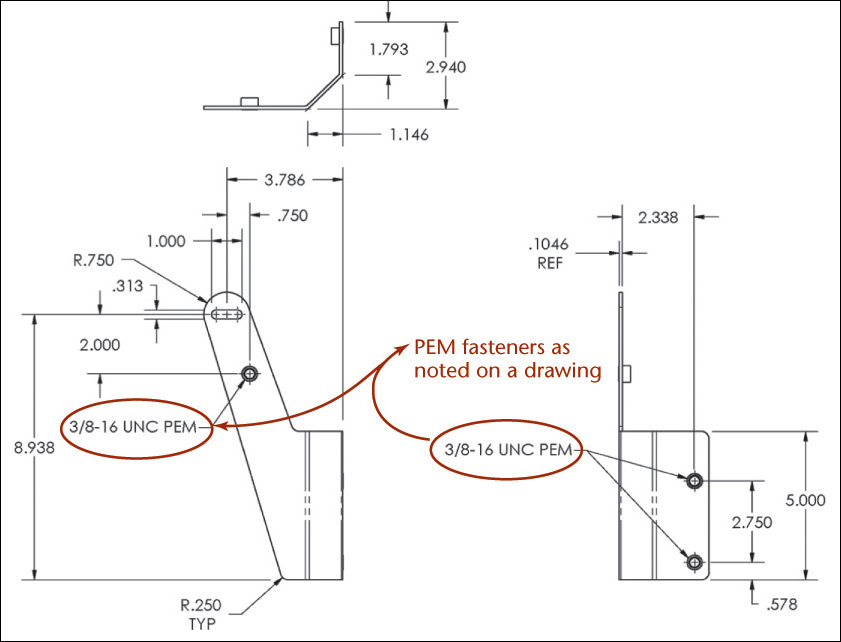
The CAD files that you download can be inserted into your drawings to save drawing time. The stock fastener type is specified in a drawing note as shown in Figure B.
Data sheets in PDF format are also available from the PEM site. Figure C shows the cover of a 12-page PDF booklet that lists material, thread size, performance data, and other key data for unified and metric self-clinching nuts sold by PEM.

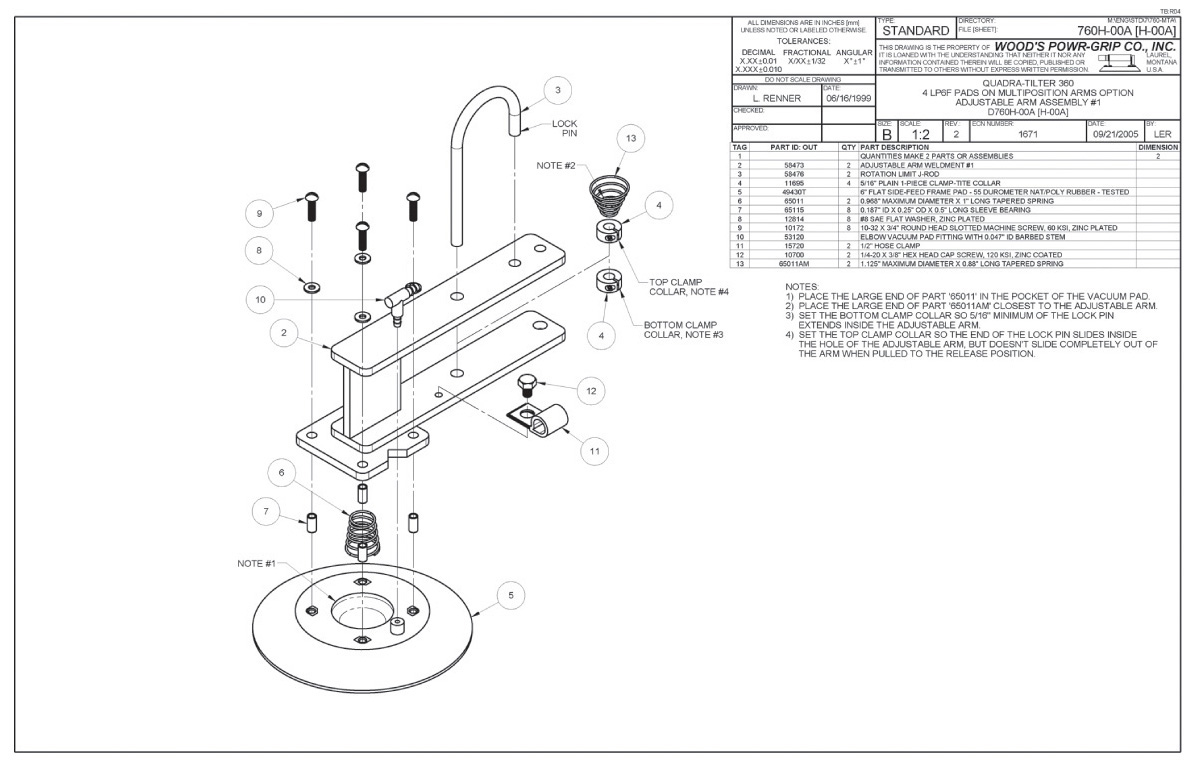
Assembly Drawing Showing Fasteners and Springs (Courtesy of Wood’s Power-Grip Co. Inc.)
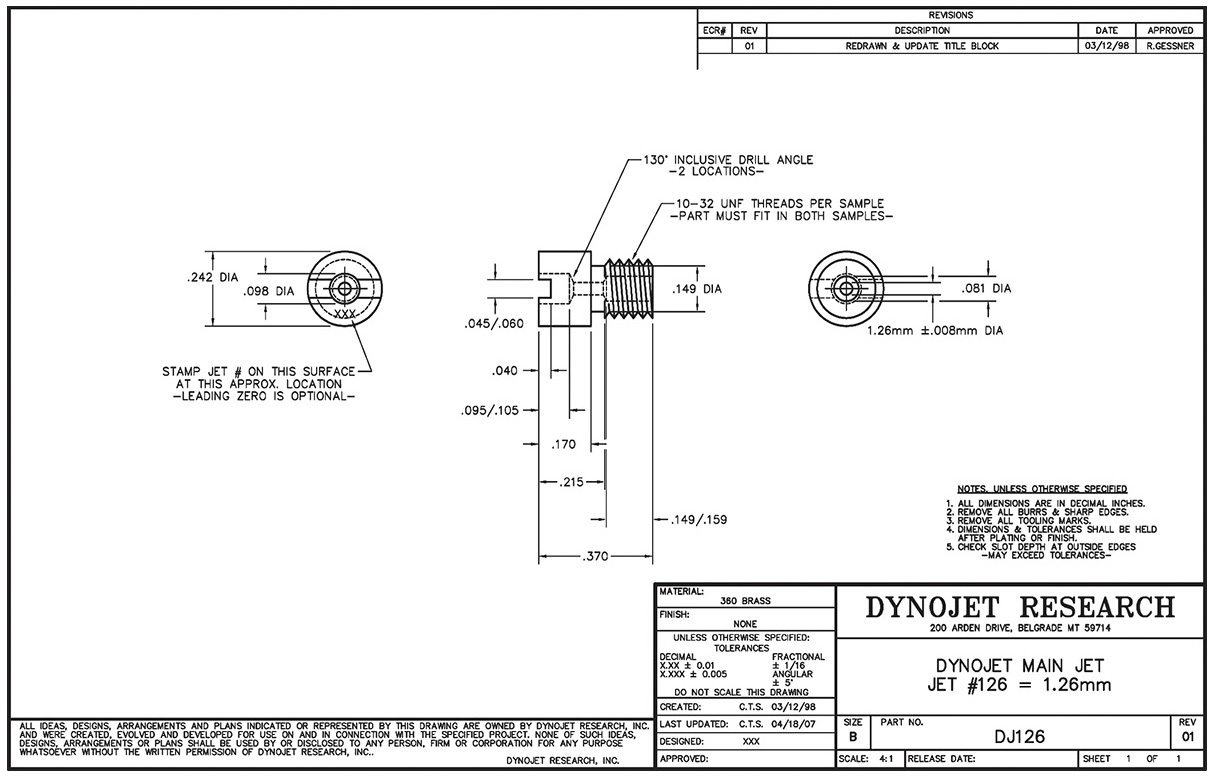
Part Drawing for a Special-Purpose Threaded Part (Scale 4:1) (Courtesy of Dynojet Research, Inc.)

Unified Extra Fine Thread Series
Chapter Summary
• There are many types of thread forms; however, metric and unified are the most common.
• The method of showing threads on a drawing is called the thread representation. The three types of thread representation are detailed, schematic, and simplified.
• The major diameter, pitch, and form are the most important parts of a thread specification.
• Thread specifications are dimensioned using a leader, usually pointing to the rectangular view of the threaded shaft or to the circular view of a threaded hole. The thread specification tells the manufacturing technician what kind of thread needs to be created.
• The nut and bolt is still the most common type of fastener. Many new types of fasteners are being created to streamline the production process.
• Keys and pins are special fasteners for attachment; for example, attaching a pulley to a shaft.
• The screw head determines what kind of tool will be necessary to install the fastener.
Review Questions
1. Draw a typical screw thread using detailed representation, and label the parts of the thread.
2. Why are phantom lines used to represent the middle part of a long spring?
3. Draw several types of screw heads.
4. List five types of screws.
5. Why is the simplified thread representation the most commonly used drawing style?
6. List five fasteners that do not have any threads.
7. Write out a metric thread specification and a unified thread specification and label each part of the specification.
8. Which type of thread form is used on a lightbulb?
9. How are multiple threads designated in a thread note?
10. Using abbreviations, give a specification for a slotted headless flat point set screw.
Chapter Exercises
Design Project
Design a system that uses thread to transmit power, for use in helping transfer a handicapped person from a bed to a wheelchair. Use either schematic or detailed representation to show the thread in your design sketches.
Thread and Fastener Projects
Use the information in this chapter and in various manufacturers’ catalogs in connection with the working drawings at the end of the next chapter, where many different kinds of threads and fasteners are required. Several projects are included here (Exercises 13.1 to 13.5).

Exercise 13.1 Draw specified detailed threads arranged as shown. Omit all dimensions and notes given in inclined letters. Letter only the thread notes and the title strip. (Some dimensions are given to help you match the sheet layout.)
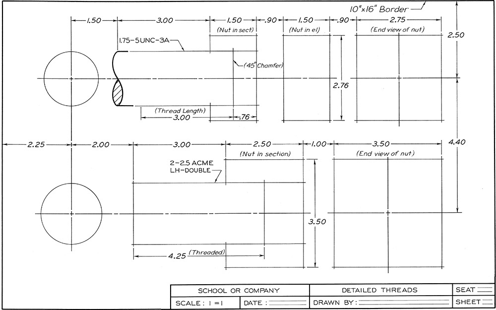
Exercise 13.2 Draw specified detailed notes given in inclined letters. Letter only the thread notes and the title strip. (Some dimensions are given to help you match the sheet layout.)
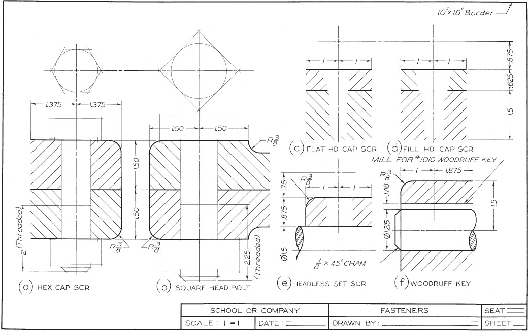
Exercise 13.3 Draw fasteners, arranged as shown. At (a) draw ![]() Hex Cap Screw. At (b) draw
Hex Cap Screw. At (b) draw ![]() Sq Hd Bolt. At (c) draw
Sq Hd Bolt. At (c) draw ![]() Flat Hd Cap Screw. At (d) draw
Flat Hd Cap Screw. At (d) draw ![]() Fil Hd Cap Screw. At (e) draw
Fil Hd Cap Screw. At (e) draw ![]() Headless Slotted Set Screw. At (f) draw front view of No. 1010 Woodruff key. Draw simplified or schematic thread symbols as assigned. Letter titles under each figure as shown. (Some dimensions are given to help you match the sheet layout.)
Headless Slotted Set Screw. At (f) draw front view of No. 1010 Woodruff key. Draw simplified or schematic thread symbols as assigned. Letter titles under each figure as shown. (Some dimensions are given to help you match the sheet layout.)
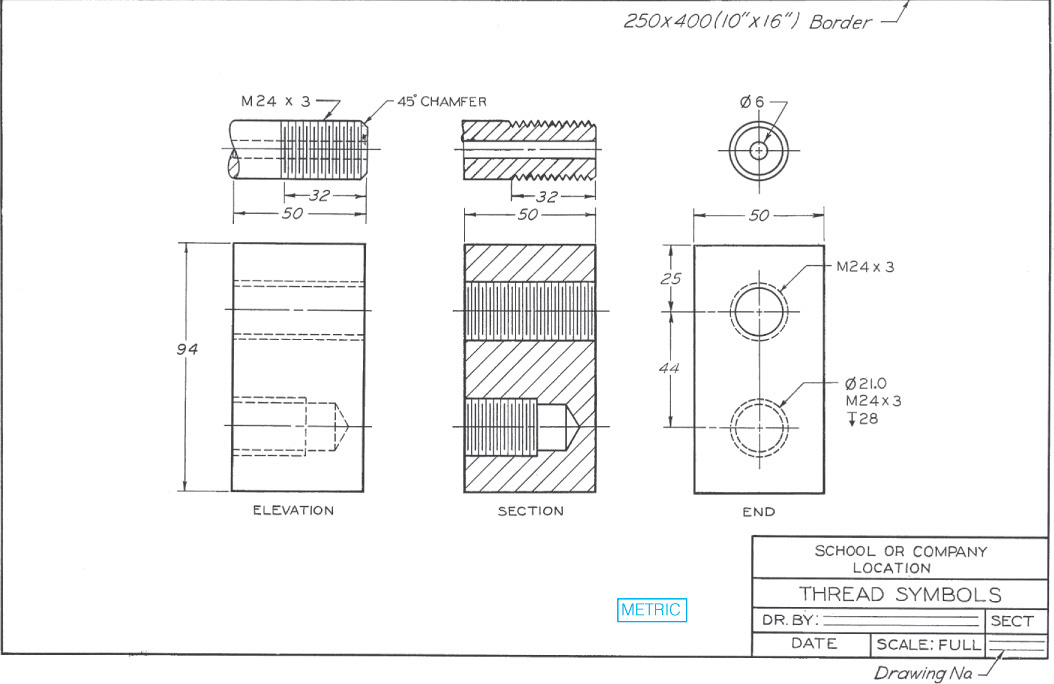
Exercise 13.4 Draw specified thread symbols, arranged as shown. Draw simplified or schematic symbols, as assigned by instructor, using Layout B-5 or A3-5. Omit all dimensions and notes given in inclined letters. Letter only the drill and thread notes, the titles of the views, and the title strip. (Some dimensions are given to help you match the sheet layout.)
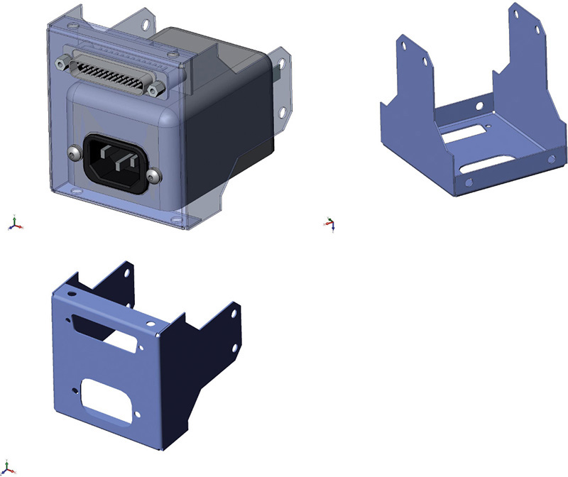
Exercise 13.5 Specify fasteners for attaching the sheet metal and standard electrical components shown. Use the Web to research power and electrical connectors.
Exercise 13.6 Captive hardware is a term for fasteners that, once installed, cannot be easily or accidentally removed. This is typically achieved by removing a portion of the threading on a screw shaft and then threading the captive hardware into a special sleeve that, once installed, prevents the hardware from backing out. Captive hardware is useful in situations where many fasteners are necessary—for example in sheet metal covers and large panels and when the fastener must be repeatedly unfastened and refastened.
For this exercise, modify a standard 6–32 × .75″ socket head cap screw (SHCS) so it can be installed into a sleeve that you will design. The dimensions for the lock and flat washer are provided on the facing page, and the dimensions from the screw to be modified are provided from a CAD file downloaded from the McMaster-Carr website. Provide dimensions for turning down the thread on the 6–32 SHCS and the missing callouts on the captive screw sleeve. Ensure the dimensions provided for the threaded portion of the screw and the clearance for the captive screw sleeve allow the screw to be fully inserted and allow it to be completely removed from the threaded blank material without causing interference.