The Vision System
The colour TV system is based on the principle that with three suitable primary colours of light (red, green and blue) it is possible to reproduce white and a gamut of colours. The precise ‘colour’ one sees depends on the relative amounts of red, green and blue light.
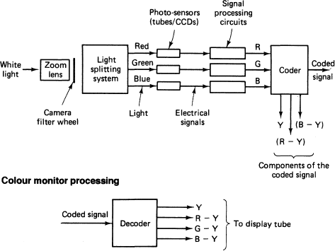
In colour television the display tube on the colour monitor generates three separate red, green and blue (RGB) pictures, which produce an appropriate mixture at any point on the screen, and the viewer sees a particular colour. It is the colour camera’s function to derive the appropriate RGB signals which eventually feed to the display. Colour cameras use a light-splitting system behind the zoom lens; this splits the light into red, green and blue light, which is then focused onto the appropriate camera tube or CCD imager as an optical image of the scene to be televised.
Scanning
The optical image is converted by the sensor into an electrical charge pattern which is ‘read out’ or ‘scanned’ in a regular pattern to produce an electrical signal. In the UK the scanning process operates at 625 lines/picture; in the USA it operates at 525 lines. The picture rate is repeated at 25 pictures/ second for the UK and 30 pictures/second for the USA; this is to ensure that the displayed picture is seen as a continuous picture and not as a scanning spot.
Interlace
By scanning first the odd lines of the picture and then the even lines (interlacing) the effective picture rate is doubled, and flicker is significantly reduced. This is known as interlaced scanning.
Coding
To avoid having to transmit three separate video signals (RGB), they are coded into one composite signal. This conveys both brightness information (luminance signal, indicated by the symbol Y) and colour information (chrominance signal, consisting of R-Y and B-Y). There are three basic incompatible systems for coding: NTSC, PAL and SECAM.
Colour picture monitors respond to both parts of the signal, while monochrome monitors extract only the brightness (luminance) information.
To ensure that the picture on the monitor is displayed in perfect synchronism with the cameras’ scanning process, synchronising pulses are added to the coded signal in the coder.
Bandwidth
The video system must be capable of reproducing fine detail in a picture. This represents an extremely high-frequency signal, greater than five million cycles per second (5 MHz) when using a 625-line system. All parts of the vision system must therefore be capable of handling a wide bandwidth of frequencies, from 50 Hz to 5 MHz; this illustrates one of the cost problems of vision systems. (An audio system, by comparison, involves a bandwidth of 30 Hz to 16 kHz.)
The basic principle of additive mixing can be represented by a colour triangle. Red, green and blue are the primary colours; magenta, cyan and yellow are the complementary or secondary colours.

Overview of the camera
Most lightweight combined camera-recorders record the ‘component’ signals.

The colour monitor has a decoder which is able to derive the G-Y signal as well as the ‘components’; these are then used to control the brightness of the appropriate colour phosphor on the tube, i.e., (R-Y)-Y=R signal.
