Signal Processing (Camera Control Unit)
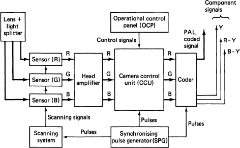
The three signals, RGB, derived from the camera sensors require electronic processing before they are coded to provide the camera output signal. Modern cameras house all the processing electronics and the coder in the camera head, with some provision for remote control of important facilities. Older cameras carried out this signal processing in a separate camera control unit (CCU).
Control features
Typically the processing, mentioned in the manufacturer’s literature, includes:
● Detail enhancement—special high-frequency correction used to improve the rendition of fine detail. It should be used with care: if over-corrected the pictures will look ‘edgy’ and artificially sharp, faces will look leathery in appearance due to the enhancement of spots, blemishes, skin pores etc. Noise is increased by detail enhancement.
● Black-level adjustment (lift)—used to establish the black level in a picture. In lightweight cameras this should be an automatic function.
● Gamma correction—the display tube has a non-linear law (see opposite). To compensate for this the RGB signals are pre-distorted in the camera to produce an overall effect which is approximately linear. Occasionally, gamma correction is used as an operational control to change the ‘law’ of the camera, i.e. to stretch or crush the dark areas of the picture. Stretching the dark areas will also increase the noise.
● Iris—remote control of the iris is essential to good vision control. It should be carefully adjusted to ensure correct exposure of the scene. Auto-iris should only be used on lightweight cameras when it is impossible to operate the iris, e.g. following rapid action between many areas the camera operator is preoccupied with framing and focus.
● Gain (master gain)—provides an increase in amplification to the video signal when operating in low-light conditions. Usually it is provided as switched increases in gain, e.g. a 6 dB increase in gain will double the signal level, equivalent to opening up the iris by one stop. Unfortunately, any increase in gain is accompanied by an increase in noise. When white balancing the cameras, the individual gain controls on the R and B channels will be adjusted to match signal levels with the G channel. This is usually an automatic facility on modern cameras. See page 60.
● Linear matrix—the deficiencies of the colour analysis by the light-splitting block and pick-up devices, can be compensated for by a small amount of coupling between the RGB signals. This improves the colour rendition of the camera.
The CCU originates appropriate control voltages and scanning signals for the camera sensors. Remote control panels are grouped together for ease of vision control and line-up.
Basic block diagram of a colour camera channel

Need for contrast law correction (gamma correction)

The linear camera law is modified by the gamma corrector to take account of the non-linear response of the display tube; this results in an approximately linear relationship between ‘light into camera’ and ‘light out from display’.
Typical switched gain settings
| Switched gain | Single device cameras | 3-device cameras |
| 1 | + 6dB (equivalent to opening up by 1 stop) | + 9dB (equivalent to opening up by 1 ½ stops) |
| 2 | +12 dB (equivalent to opening up by 2 stops) | +18 dB (equivalent to opening up by 3 stops) |
Because all forms of correction introduce extra noise on the signals it is usual for manufacturers to specify the signal-to-noise (S/N) ratio with all correction switched out, i e. a ‘flat’ channel with gamma correction off, detail enhancement off, linear matrix out etc.
