Lighting Control: Dimmers (Analogue)
A dimmer is an electrical device used to control the light output from a luminaire. It should:
● Provide continuously variable control of the light output.
● Be easy to remotely control the dimmer with a simple fader.
● Dim the light progressively, with an appropriate law, which should not vary with the load, whether it be a 2 kW or 150 W lamp.
● Not be wasteful of power.
● Not cause interference to other equipment and be silent in operation.
● Be compact.
● Be easy to maintain.
Thyristor or SCR dimmers
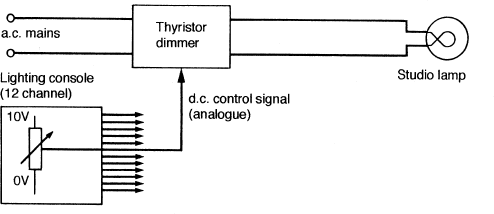
The modern dimmer consists of two thyristors or silicon-controlled rectifiers (SCR) connected back-to-back as shown in figure C. The diodes do not conduct until switched on by a suitable pulse at the gate electrode (G). D1 conducts on positive mains half-cycles and D2 on negative mains half-cycles. The control voltage (0–10 V) on the fader is therefore used in a control amplifier to produce suitably delayed or advanced gating pulses. The voltage waveform to the lamp is therefore a chopped sinusoidal shape.
Interference
The thyristor dimmer satisfies most of the requirements listed above except one—interference. The very rapid switch-on of the load current can cause pulses of interference at 100 Hz (and harmonics of 100 Hz) on to adjacent microphone cables. This can also cause excessive vibrations of the lamp filament in the luminaire.
The interference can be reduced by:
● Including an inductor in the dimmer circuit. This reduces the rate of rise of the load current and results in reduced interference and less filament vibration.
● Using special screened quad cable for microphone circuits. This produces a marked decrease in interference pick-up (28 dB) and is used in many major TV studios.
Digital-multiplex control
Digital-multiplex control (DMX 512) enables a lighting console to provide a single control signal in digital form which can be decoded at the dimmer racks to provide the appropriate 0–10 V dimmer control signal for all the dimmers. This simplifies the distribution of control signals to the dimmers especially when used on location. The DMX 512 system can handle 512 dimmers and can also be used for control of moving lights and scrollers.

B. Typical fader law
The fader law follows an approximately square law, providing an apparently linear change of illumination with fader movement.
C. Silicon-controlled rectifiers
1. Waveform of the sinusoidal mains voltage applied to the silicon controlled rectifiers D1 and D2.
2. Waveform of the gating pulses applied to switch the SCR gate (G).
3. Resultant load-current waveform.
D. Reducing interference
4. Basic SCR dimmer circuit with the inductor (L) included for interference suppression.
5. Waveform of the load current, showing the effect of the inductor on the rise time of the current.

