Vision Mixer or Switcher: Function
The vision mixer or switcher is the destination point for all picture sources in the studio. The output of all the studio cameras, telecine machines, videotape recorders (when ‘playing in’ inserts to a programme), caption scanners (film strips and slides) are connected to the inputs of the vision mixing unit (or switcher).
The function of the desk is to edit together (by cutting, mixing, etc.) all these various contributions to the production, as the director has planned.
The output of the switcher (studio output) is connected, via distribution amplifiers, to the transmission monitor in the production control area, and to the transmission chain, check monitors, etc., that comprise the television complex. The switcher is located in the production control area.
Vision mixer design
Although many designs of switcher exist, each with its own merits and limitations, the principles involved are simple enough. A flexible vision mixer should be able to cut, mix, fade up or out, superimpose, and provide effects facilities such as wipes, split screen, chroma key and downstream keyer.
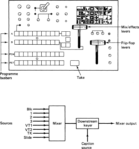
The operational panel of the switcher should be well laid out and easy to operate. Figure 1 opposite shows a typical panel layout for a basic switcher in which each picture source is available for button selection on a number of horizontal ‘busbars’. This switcher incorporates all the facilities mentioned above plus a master fader.
The downstream keyer provides the facility for black/white captions to be inserted after all the switching functions, thus ensuring that a caption is ‘in front’ of all parts of the picture. The captions, although faded up, are not superimposed but inserted into the picture, i.e. inlaid, for better legibility.
The master fader enables the output of the switcher to be easily faded to black/faded up from black.
What to look for
No matter how inexpensive your system your vision mixer should fit your projected requirements. All switching operations should be accomplished without any ‘break up’ or ‘roll’ on the transmission monitor. Also the quality of the outgoing picture should be identical to that of the input picture.
Be warned! Sophisticated mixing panels do not in themselves produce better production techniques. Unskilled operation can lead to embarrassing ‘on air’ errors. Even when mistakes can be rectified by re-recording, this can prove time-consuming—and is often costly.

Typical panel for a small studio vision mixer
Each picture source (channel) is connected to the same numbered button on each of the busbars or banks of the mixer (A, B, Programme, Preset). The first button is fed with Black; usually this is followed by Camera 1, Camera 2, Camera 3 etc.
This mixer will allow cutting between sources on the programme busbar, mixing between two sources by presetting the new source on the preset busbar and changing the faders (bottom left). Complex wipes and chroma key set-ups are achieved using the A/B banks together with the wipe selection panel, chroma-key controls and the mix/effects levers.
A useful addition to this is a downstream keyer which inserts captions into the final picture compilation (2). This enables captions to be faded up/down, and also allows the captions to have black edges/drop shadow/colour borders to improve the visibility of the lettering and allow the colour of the captions to be changed to suit the programme material.
