Chapter 11. Manage Storage
This chapter covers the following topics:
• Mulitpathing, Storage Policies, and vVols
This chapter contains information related to VMware 2V0-21.20 exam objectives 1.3.1, 1.3.2, 1.3.3, 1.3.4, 1.3.5, 1.4, 1.6.5, 1.9.1, 5.5, 7.4, 7.4.1, 7.4.2, 7.4.3
This chapter provides information on configuring and managing storage in a vSphere environment.
“Do I Know This Already?” Quiz
The “Do I Know This Already?” quiz allows you to assess whether you should study this entire chapter or move quickly to the “Exam Preparation Tasks” section. Regardless, the authors recommend that you read the entire chapter at least once. Table 11-1 outlines the major headings in this chapter and the corresponding “Do I Know This Already?” quiz questions. You can find the answers in Appendix A, “Answers to the ‘Do I Know This Already?’ Quizzes and Review Questions.”
Table 11-1 ”Do I Know This Already?” Section-to-Question Mapping

1. You are configuring a hybrid vSAN cluster in a vSphere 7.0 environment. By default, what percentage of the flash space is used as a write buffer?
a. 100%
b. 70%
c. 30%
d. 0%
2. You are configuring vSAN in a vSphere 7.0 environment. Which of the following is supported when using Quickstart to configure a vSAN cluster?
a. ESXi 6.5.0
b. Network Resource Control version 2.
c. Hosts with dissimilar network configurations
d. Fibre channel storage
3. You want to increase the size of a VMFS 6 datastore. Which one of the following statements is true?
a. You can extend the datastore using available space on the storage device that is backing the datastore.
b. You can expand the datastore using a separate storage device.
c. If the datastore is 100% full, you cannot increase its capacity.
d. You can expand the datastore using available space on the storage device that is backing the datastore
4. You are configuring NFS datastores for your vSphere 7.0 environment. Which one of the following statements is true?
a. You can use multiple IP addresses with any NFS datastore.
b. You can use multiple IP addresses with any NFS 4.1, but not NFS 3.
c. You can use multiple IP addresses with any NFS 3, but not NFS 4.1.
d. You cannot use multiple IP addresses with any NFS.
5. You are configuring SIOC and want to change the threshold it uses to begin prioritizing I/O based on shares. Which of the following options is the acceptable range?
a. 1 to 100 ms
b. 10 to 100 ms
c. 30 to 100 ms
d. 10 to 50 ms
6. You want to perform maintenance on a datastore that is a member of a datastore cluster. Which of the following actions should you take?
a. Right-click the host and choose Enter Maintenance Mode
b. Right-click the datastore and choose Enter Maintenance Mode
c. Right-click the host and choose Enter SDRS Maintenance Mode
d. Right-click the datastore and choose Enter SDRS Maintenance Mode
7. You need to configure an ESXi 7.0 host to access shared NVMe devices using RDMA over Converged Ethernet (RoCE) version 2 protocol. Which steps should you take? (Choose three.)
a. Configure a VMkernel network adapter
b. Add a software adapter to the host’s network adapters
c. Navigate to Storage Adapters > RDMA Adapters and verify the VMkernel adapter bindings
d. Navigate to Networking > RDMA Adapters and verify the VMkernel adapter bindings
e. Add a software adapter to the host’s storage adapters
8. In a vSphere 7.0 environment, you want to allow a virtual machine to use NVDIMMs as standard memory. What should you configure?
a. vPMemDisk
b. vPMem
c. NVMe-oF
d. RDMA
9. You want to set the path selection policy for a storage device managed by NMP such that it uses a preferred path. Which of the following policies should you choose?
a. FIXED
b. LB_RR
c. VMW_PSP_FIXED
d. VMW_PSP_RR
10. You are preparing to configure vVols in a vSphere 7.0 environment. Which of the following components should you configure in the storage system? (pick two).
a. Protocol endpoints
b. Storage containers
c. LUNs
d. Virtual volumes.
Foundation Topics
Configure and Manage vSAN
This section provides information for configuring and managing vSAN clusters and vSAN datastores.
Prepare for VSAN
Before creating and configuring vSAN clusters, you should be aware of the following VSAN characteristics.
![]()
• Multiple vSAN clusters can be configured in a single vCenter Server instance
• vSAN does not share devices with other vSphere features.
• At a minimum, a vSAN cluster must include three hosts with capacity devices. Additionally, it can include hosts with or without capacity devices.
• For best results, use uniformly configured hosts in each vSAN cluster.
• If a host contributes capacity, it must have at least one flash cache device and one capacity device.
• In hybrid clusters, the magnetic disks are used for capacity and flash devices serve as a read cache and a write buffer. 70 percent of the flash space is used for read cache and 30 percent is used for write buffer.
• In all-flash clusters, one designated flash device is used as a write cache, additional flash devices are used for capacity. No read cache is used. All read requests come directly from the flash pool capacity.
• Only local (or direct-attached) devices can participate in a vSAN cluster.
• Only ESXi 5.5 Update 1 or later hosts can join a vSAN cluster.
• Before you move a host from a vSAN cluster to another cluster, make sure that the destination cluster is vSAN enabled.
• To use a vSAN datastore, an ESXi host must be a member of the vSAN cluster
Verify that you meet all the VSAN hardware, cluster, software, and network requirements described in Chapter 2, “Storage Infrastructure.”
Create a VSAN Cluster with Quickstart
Quickstart, which is described in Chapter 10, allows you to quickly create, configure, and expand a vSAN cluster, using recommended default settings for networking, storage, and services. It uses the vSAN health service to help you validate and correct configuration issues using a checklist consisting of green messages, yellow warnings, and red failures.
To use Quickstart to configure a vSAN cluster, the hosts must use ESXi 6.0 Update 2 or later. The hosts must have a similar network configuration to allow Quickstart to configure network settings based on cluster requirements. You can use Quickstart to configure vSAN on an existing cluster by using the following procedure.
Step 1. In the vSphere Client, select the cluster in the Hosts and Clusters inventory.
Step 2. Click Configure > Configuration > Quickstart.
Step 3. On the Cluster basics card, click Edit,
a. Provide select the vSAN service.
b. Optionally, select other services, such as DRS and vSphere HA.
c. Click Finish
Step 4. Click Add Hosts > Add and use the wizard to add hosts to the cluster.
Step 5. On the Cluster Configuration card, click Configure and use the wizard to configure the following.
• On the Configure the distributed switches page, enter networking settings, including distributed switches, port groups, and physical adapters.
• On the vMotion traffic page, enter the vMotion IP address information.
• On the Storage traffic page, enter the storage IP address information
• On the Advanced options page, provide vSAN cluster settings. Optionally, provide settings for DRS, HA, and EVC.
• On the Claim disks page, select disks on each host to claim for vSAN cache and capacity.
• Optionally, on the Create fault domains page, define fault domains for hosts that can fail together.
• On the Ready to complete page, verify the cluster settings, and click Finish.
Note
If you are running vCenter Server on a host, the host cannot be placed into maintenance mode as you add it to a cluster using the Quickstart workflow. The same host also can be running a Platform Services Controller. All other virtual machines on the host must be powered off.
Note
Distributed switches with network resource control version 2 cannot be used for vSAN Quickstart.
Manually Enable VSAN
While it is recommended that all of the ESXi hosts in a vSAN cluster contribute storage to that vSAN cluster, it is not required, and ESXi hosts without any capacity can be added to, and make use of, the vSAN cluster. This is possible, provided the following requirements are met:
• There are at least 3 ESXi hosts in the vSAN cluster, and they all must contribute storage or the cluster cannot tolerate host and/or device failures.
• At least ESXi 5.5 Update 1 or higher on all the hosts in the cluster.
• If a host is being moved from one vSAN cluster to another, vSAN must be enabled on the destination cluster.
• ESXi hosts must be a member of the vSAN cluster to access the vSAN datastore (regardless of whether they are contributing storage to the vSAN cluster).
You can use the following procedure to manually enable vSAN.
Step 1. Prepare a VMkernel network adapter on each participating host.
• In the vSphere Client, select a host in the inventory pane.
• Navigate to Networking > VMkernel adapters
• Click the Add Networking icon
• Use the wizard to configure the adapter’s network settings and to enable vSAN.
Step 2. In the inventory pane, right-click a data center and select New Cluster
Step 3. Provide a name for the cluster
Step 4. Optionally, configure other cluster settings, such as DRS, vSphere HA, and EVC.
Step 5. Add hosts to the cluster.
Step 6. Navigate to Configure > VSAN > Services and click Configure.
Step 7. Select one of the following configuration types and click Next.
• Single site cluster
• Two host cluster
• Stretched cluster
Step 8. In the next wizard page, optionally configure the following options and click Next.
• Enable Deduplication and Compression on the cluster.
• Enable Encryption and select a KMS.
• Select Allow Reduced Redundancy check box to enable encryption or deduplication and compression on a vSAN cluster that has limited resources.
Step 9. On the Claim disks page, select the disks for use by the cluster and click Next.
Step 10. Follow the wizard to complete the configuration of the cluster, based on the fault tolerance mode.
• For a two host vSAN cluster: Choose a witness host for the cluster and claim disks for the witness host.
• For a stretched cluster: Define fault domains for the cluster, choose a witness host, and claim disks for the witness host.
• If you selected fault domains: Define the fault domains for the cluster.
Step 11. On the Ready to complete page, click Finish.
Note
When claiming disks for each host that contributes storage to a vSAN cluster, select one flash device for the cache tier, and one or more devices for the capacity tier.
Edit vSAN Settings
You can modify the settings of an existing vSAN cluster using the following procedure.
Step 1. In the vSphere Client, the cluster in the inventory pane
Step 2. Navigate to Configure > vSAN > Services
Step 3. Click Edit.
Step 4. Modify the following services as you wish.
• Deduplication and compression
• vSAN Encryption
• vSAN performance service
• iSCSI target
• Advanced Settings > Object Repair Timer
• Advanced Settings > Site Read Locality for stretched clusters
• Thin Swap provisioning
• Large Cluster Support for up to 64 hosts
• Automatic Rebalance
Step 5. Click Apply.
License VSAN
vSAN must be licensed to work outside of its evaluation period. The license capacity is based on the total number of CPUs in the hosts participating in the cluster. The vSAN license used is recalculated whenever ESXi hosts are added to or removed from the vSAN cluster.
You can use the following procedure to assign a vSAN license to a cluster. The Global.Licenses privilege is required on the vCenter Server.
Step 1. In the vSphere Client, select the vSAN cluster in the inventory pane.
Step 2. Click the Configure tab.
Step 3. Right-click the vSAN cluster
Step 4. Choose Assign License.
Step 5. Select an existing license and click OK.
Note
You can use vSAN in evaluation mode to explore its features for 60 days. To continue using vSAN beyond the evaluation period, you must license the cluster. Some advanced features, such as all-flash configuration and stretched clusters, require a license that supports the feature.
View a vSAN Datastore
When you enable vSAN on a cluster a vSAN datastore is created. You can use the following procedure to review the capacity and other details of the vSAN datastore.
Step 1. In the vSphere Client, navigate to Home > Storage.
Step 2. Select the vSAN datastore.
Step 3. Click the Configure tab.
Step 4. Review the following.
• Capacity (total capacity, provisioned space, and free space)
• Datastore capabilities
• Policies
A vSAN datastore’s capacity depends on the capacity devices per host and the number of hosts in the cluster. For example, if a cluster includes eight hosts, each having seven capacity drives, where each capacity drive is 2 TB, then the approximate storage capacity is 8 x 7 x 2 TB = 112 TB.
Some capacity is allocated for metadata, depending on the on-disk format version.
• On-disk format version 1.0 adds approximately 1 GB overhead per capacity device.
• On-disk format version 2.0 adds overhead that is approximately 1-2 percent of the total capacity
• On-disk format version 3.0 and later adds overhead that is approximately 1-2 percent of the total capacity plus overhead for checksums used by deduplication and compression (approximately 6.2 percent of the total capacity)
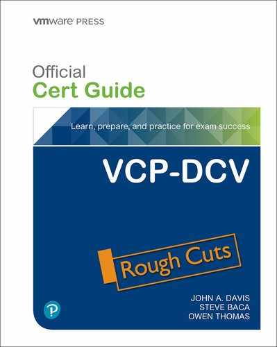
Configure VSAN and vSphere HA
You can enable vSphere HA and vSAN on the same cluster, but with some restrictions.
The following ESXi requirements apply when using vSAN and vSphere HA together.
• ESXi version 5.5 Update 1 or later must be used on all participating hosts.
• The cluster must have a minimum of three ESXi hosts.
The following networking differences apply when using vSAN and vSphere HA together
• The vSphere HA traffic flows over the VSAN network rather than the management network.
• vSphere HA uses the management network only when vSAN is disabled.
To enable vSAN on an existing vSphere HA cluster, you must first disable vSphere HA before enabling vSAN. After vSAN is enabled, you can re-enable vSphere HA.
Table 11-2 provides vSphere HA networking differences between clusters where vSAN is and is not enabled.
Table 11-2 Network Differences in vSAN and non-vSAN Clusters
You must account for the vSAN’s rule set’s Primary Level of failures to tolerate setting when configuring vSphere HA the admission control policy. The vSAN primary level of failures must not be lower than the capacity reserved by the vSphere HA admission control setting. If vSphere HA reserves less capacity, failover activity might be unpredictable. For example, for an eight-host cluster, if you set the vSphere HA admission control to more than 25 percent of the cluster resources, then you should not set the vSAN rule’s Primary Level of failures to tolerate to higher than two hosts.
In response to events involving the failure of multiple hosts in a cluster where vSphere HA and vSAN are enabled, vSphere HA may not be able to restart some virtual machines, where the most recent copy of an object is inaccessible. For example, consider the following scenario.
• In a three-host cluster with vSAN and vSphere HA enabled, two hosts fail.
• A VM continues to run on the third host
• The final host fails.
• The first two hosts are recovered
• vSphere HA cannot restart the VM, because the most recent copy of its objects is on the third host, which is still unavailable.
Set the HA Capacity Reservation Setting
Capacity can be reserved for failover in the vSphere HA admission control policies. When this is used, it must be coordinated with the vSAN policy, Primary level of failures to tolerate. The HA reserved capacity cannot be higher than the vSAN Primary level of failures to tolerate.
For example, if you set a vSAN Primary level of failures to tolerate to 1, then the HA admission control policy must reserve enough resource that is equal to 1 host. If you set the vSAN Primary level of failures to tolerate to 2, then the HA admission control policy must reserve enough resource that is equal to 2 ESXi hosts.
Disable vSAN
You can use the following procedure to disable vSAN for a host cluster, which causes all virtual machines located on the vSAN datastore become inaccessible.
Step 1. In the vSphere Client, select the cluster in the inventory pane.
Step 2. Verify that host in the cluster is in maintenance mode.
Step 3. Click Configure > vSAN > Services.
Step 4. Click Turn Off vSAN.
Step 5. In dialog box, confirm your selection.
Note
If you intend to use virtual machine while vSAN is disabled, make sure you migrate virtual machines from vSAN datastore to another datastore before disabling the vSAN cluster.
Shutdown and Restart VSAN
Whenever you want to shut down the entire vSAN cluster prior to performing some maintenance activities, vSAN does not have to be disabled. The following procedure details how you can shut down a vSAN cluster:
![]()
Step 1. Power off all virtual machines in the vSAN cluster, except the vCenter Server if it is running in the cluster.
Step 2. In the vSphere Client, select the cluster, and navigate to Monitor > vSAN > Resyncing Objects.
Step 3. Wait until all resynchronization tasks are complete.
Step 4. On the Configure tab, turn off DRS and HA.
Step 5. On each host, use the following command to disable cluster member updates
esxcfg-advcfg -s 1 /VSAN/IgnoreClusterMemberListUpdates
Step 6. If vCenter Server runs in the vSAN cluster, shut it down, which means makes the vSphere Client unavailable
Step 7. On each host, use the following command to place the hosts in the maintenance mode with no data migration.
esxcli system maintenanceMode set -e true -m noAction
Step 8. Shutdown each host.
Note
When you plan to shut down the vSAN cluster, you do not need to disable vSAN on the cluster.
After you perform maintenance activities you can restart the vSAN cluster using the following procedure.
Step 1. Power on the hosts.
Step 2. Use the host direct consoles to monitor the ESXi startup
Step 3. Optionally, use a web browser to connect directly to the ESXi Host Client to monitor the host’s status, events, and logs. You may ignore misconfiguration status messages that may appear temporarily while less than three hosts have come online and joined the cluster.
Step 4. On each host, use the following commands to exit maintenance mode and to ensure each host is available in the cluster
esxcli system maintenanceMode set -e false
esxcli vsan cluster get
Step 5. Restart the vCenter Server VM.
Step 6. On each host, us the following command to re-enable updates.
esxcfg-advcfg -s 0 /VSAN/IgnoreClusterMemberListUpdates
Step 7. In the vSphere Client, select the vSAN cluster in the inventory pane.
Step 8. On the Configure tab, re-enable DRS and HA.
Step 9. You can now start virtual machines in the cluster and monitor the vSAN health service.
Deploy vSAN with vCenter Server
You can simultaneously deploy a VCSA and create a VSAN cluster, by using the vCenter Server Installer and selecting the following options.
• Create a single-host vSAN cluster.
• Place the vCenter Server on the host in the cluster.
• During Stage 1, choose Install on a new vSAN cluster containing the target host.
This process will deploy a one-host vSAN cluster. After the deployment, you can use the vSphere Client to configure the vSAN cluster and add additional nodes to the cluster.
Expand a VSAN Cluster
vSAN clusters can be expanded by adding ESXi hosts with storage to the cluster. Keep in mind that ESXi hosts without local storage can still be added to a vSAN cluster. You can use the following procedure to expand your vSAN cluster by adding hosts.
Step 1. In the vSphere Client, locate the cluster in the inventory pane.
Step 2. Right-click the cluster and select Add Hosts
Step 3. Use the wizard, you can add one hosts using one of the following options.
• New hosts (provide the host name and credentials)
• Existing hosts (select a host in the inventory that is not yet in the cluster)
Step 4. Complete the wizard and click Finish on the final page.
You can also use the following procedure to move multiple, existing ESXi hosts into the vSAN cluster using host profiles.
Step 1. In the vSphere Client, navigate to Host Profiles.
Step 2. Click the Extract Profile from a Host icon.
Step 3. Select a host in the vSAN cluster that you want to use as the reference host and click Next.
Step 4. Provide a name for the new profile and click Next.
Step 5. On the next wizard page, click Finish.
Step 6. In the Host Profiles list, select the new host profile and attach multiple hosts to the profile.
Step 7. Click Attach/Detach Hosts and clusters to a host profile icon.
Step 8. Likewise, detach the reference vSAN host from the host profile.
Step 9. In the Host Profiles list, select the new host profile and click the Check Host Profile Compliance icon.
Step 10. Select the Monitor > Compliance.
Step 11. Right-click the hosts and select All vCenter Actions > Host Profiles > Remediate.
Step 12. When prompted, provide appropriate input parameters for each host and click Next.
Step 13. Review the remediation tasks and click Finish.
When completed, the hosts and their resources are part of the vSAN cluster.
You can use the following procedure to add hosts to a vSAN cluster using Quickstart.
Step 1. Verify that no network configuration that was previously performed through the Quickstart workflow has been modified from outside of the Quickstart workflow.
Step 1. In the vSphere Client, select the vSAN cluster in the inventory.
Step 2. Click Configure > Configuration > Quickstart.
Step 3. Click Add hosts > Launch.
Step 4. Use the wizard to provide information for new hosts or to select existing hosts from the inventory.
Step 5. Complete the wizard and click Finish on the last page.
Step 6. Click Cluster configuration > Launch.
Step 7. Provide networking settings for the new hosts.
Step 8. On the Claim disks page, select disks on each new host.
Step 9. On the Create fault domains page, move the new hosts into their corresponding fault domains.
Step 10. Complete the wizard and click Finish.
Note
When adding a host to vSAN cluster using Quickstart, the vCenter Server must not be running on the host.
Work with Maintenance Mode
Before shutting down, rebooting, or disconnecting a host that is a member of a vSAN cluster, you must put the ESXi host in maintenance mode. Consider the following guidelines for using maintenance mode for vSAN cluster member hosts.
• When entering host maintenance mode, you must select a data evacuation mode, such as Ensure accessibility or Full data migration.
• When a vSAN cluster member host enters maintenance mode, the cluster capacity is automatically reduced.
• Each impacted virtual machine may have compute resource, storage resources, or both on the host entering maintenance mode.
• The Ensure accessibility mode, which is faster than the Full data migration mode, migrates only the components from the host that are essential for running the virtual machines. It does not reprotect your data. When in this mode, if you encounter a failure, the availability of your virtual machine is affected, and you might experience unexpected data loss.
• When you select the Full data migration mode, your data is automatically reprotected against a failure (if the resources are available and the Primary level of failures to tolerate set to 1 or more). In this mode, your virtual machines can tolerate failures, even during planned maintenance.
• When working with a three-host cluster, you cannot place a server in maintenance mode with Full data migration.
Prior to placing a vSAN cluster member host in maintenance mode, you must verify the following.
• If using Full data migration mode, verify that the cluster has enough hosts and available capacity to meet the requirements of the Primary level of failures to tolerate policy.
• Verify that remaining hosts have enough flash capacity exists to meet any flash read cache reservations. To analyze this, you can run the following RVC command.
vsan.whatif_host_failures
• Verify that the remaining hosts have sufficient capacity devices to handle stripe width policy requirements, if selected.
• Make sure that you have enough free capacity on the remaining hosts to handle the data that must be migrated from the host entering maintenance mode.
You can use the Confirm Maintenance Mode dialog box as a tool to determine how much data will be moved, the number of objects that will become non-compliant or accessible, and the whether or not sufficient capacity is available to perform the operation. You can also use the Data Migration Pre-check button to determine the impact of data migration options when placing a host into maintenance mode or removing it from the cluster.
To place a vSAN Cluster member host in maintenance mode, you can use the following procedure.
Step 1. In the vSphere Client, select the cluster in the inventory pane
Step 2. Optionally, use the following steps to run Data Migration Pre-check.
• Click Data Migration Pre-check.
• Select a host, a data migration option, and click Pre-check.
• View the test results and decide if you should proceed.
Step 3. Right-click the host and select Maintenance Mode > Enter Maintenance Mode.
Step 4. Select one of the following data evacuation modes and click OK
• Ensure accessibility
• Full data migration
• No data migration
Of the three data evacuation modes, Ensure accessibility is the default. If hosts are powered off or removed from a vSAN cluster, vSAN makes sure that the virtual machines on the ESXi host which is removed, can still run those virtual machines. This will move some of the virtual machine data off the vSAN cluster, but replica data will remain. If you have a three-host cluster, this is the only evacuation mode available.
Full data migration, as the name implies, will move all the VM data to other ESXi hosts in the cluster. This option makes sense if you are removing the host from the cluster permanently. If a virtual machine has data on the host and that data is not migrated off, then the host cannot enter mode.
The last option, No data migration, is also self-explanatory. If this option is selected, vSAN will not move any data from this ESXi host.
Managing VSAN Fault Domains
Fault domains provide additional protection against outage in the event of a rack or blade chassis failing. Fault domains contain at least one vSAN host based on its physical location. With fault domains, vSAN can withstand rack, blade chassis, host, disk, or network failure within one fault domain, as the replica and witness data would be stored in a different fault domain.
You can use the following procedure to create a new fault domain in a vSAN cluster.
Step 1. In the vSphere Client, examine each host in a vSAN cluster
Step 2. Verify each host is ESXi 6.0 or later (to support fault domains) and is online.
Step 3. Select the vSAN cluster in the inventory pane.
Step 4. Click Configure > vSAN > Fault Domains
Step 5. Click the Add (plus sign) icon.
Step 6. In the wizard, provide a name for the fault domain
Step 7. Select one or more hosts to add to the fault domain.
Step 8. Click Create.
You can use the vSphere Client to add hosts to an existing fault domain, by selecting Configure > vSAN > Fault Domains and dragging the host to the appropriate fault domain. Likewise, you can drag a host out of a fault domain to remove the host from the fault domain, creating a single-host fault domain.
Extend a vSAN Datastore Across Two Sites
vSAN stretched clusters extend across two physical data center locations to provide availability in the event of site failure as well as providing load balancing between sites. With stretched vSAN clusters, both sites are active, and if either site should fail, vSAN will utilize storage on the site that is still up. One site must be designated as the preferred site, which makes the other site the secondary, or nonpreferred.
You can use the following procedure to leverage Quickstart to create a stretched cluster across two sites.
![]()
Step 1. Ensure you meet the following prerequisites
• Deploy a host outside of any cluster for the witness host.
• Verify ESXi 6.0 Update 2 or later is used on each host.
• Verify the hosts in the cluster do not have any existing vSAN or networking configuration
Step 2. Click Configure > Configuration > Quickstart.
Step 3. Click Cluster Configuration > Edit
Step 4. In the wizard, provide a cluster name, enable vSAN, and optionally enable other features, such as DRS or vSphere HA.
Step 5. Click Finish.
Step 6. Click Add hosts > Add.
Step 7. In the wizard, provide information for new hosts or select existing hosts in the inventory. Complete the wizard and click Finish.
Step 8. Click Cluster configuration > Configure
Step 9. In the wizard, configure the following.
• Configure settings for distributed switch port groups, physical adapters, and IP configuration associated with vMotion and storage.
• Set vSAN Deployment type to Stretched Cluster.
• On the Claim disk page, select disks on each host for cache and capacity
• On the Create fault domains page, define fault domains for the hosts in the Preferred site and the Secondary site.
• On the Select witness host page, select a host to use as a witness host, which cannot be not part of the cluster and can have only one VMkernel adapter configured for vSAN data traffic.
• On the Claim disks for witness host page, select disks on the witness host for cache and capacity.
• On the Ready to complete page, verify the cluster settings, and click Finish.
When creating a vSAN stretched cluster, DRS must be enabled on the cluster. There are several DRS requirements as well for stretched vSAN clusters:
• Two host groups must be created: one for the preferred site and another for the secondary site
• Two VM groups must be created: one for the preferred site VMs and one for the VMs on the secondary site.
• Two VM to Host affinity rules must be created for the VMs on the preferred site, and VMs on the secondary site.
• VM-Host affinity rules must be used to define the initial placement of virtual machines on ESXi hosts in the cluster.
In addition to the above DRS requirements, there are also HA requirements for stretched vSAN clusters:
• HA must be enabled
• HA rules should allow the VM-Host affinity rules in the event of a failover
• HA datastore heartbeats should be disabled.
vSAN itself has numerous requirements to implement stretched clusters:
• Stretched clusters must use on-disk format 2.0 or higher. If your vSAN cluster is not using on-disk format 2.0, it must be upgraded before configuring the stretched vSAN cluster.
• Failures to tolerate must be set to 1.
• Symmetric Multiprocessing Fault Tolerance (SMP-FT) VMs are only supported when PFFT is at 0 and Data locality is either Preferred or Secondary. SMP-FT VMs with PFFT set to 1 or higher is not supported.
• If hosts are disconnected or fail in a not responding state, the witness cannot be added or removed.
• Adding ESXi hosts via esxcli commands on stretched clusters is not supported.
Manage Devices in a vSAN Cluster
You can use the following procedure to create a disk group on a vSAN cluster member host.
Step 1. In the vSphere Client, select the cluster in the inventory pane.
Step 2. Click Configure > vSAN > Disk Management.
Step 3. Select the host and click Create disk group.
• Select the flash device to be used for cache.
• Select the type of capacity disks to use (HDD for hybrid or Flash for all-flash).
• Select the devices you want to use for capacity.
Step 4. Click Create or OK.
You can use the following procedure to claim storage devices for a vSAN cluster
Step 1. In the vSphere Client, select the cluster in the inventory pane.
Step 2. Click Configure > vSAN > Disk Management > Claim Unused Disks.
Step 3. Select a flash device to be used as cache and click Claim for cache tier.
Step 4. Select one or more devices (HDD devices for hybrid or flash devices for all-flash) to be used as capacity and click Claim for capacity tier.
Step 5. Click Create or OK.
To verify that the proper role (cache or capacity) has been assigned to each device in an all-flash disk group, examine to the Disk Role column at the bottom of the Disk Management page.
If the vSAN cluster is set to claim disks in manual mode, you can use the following procedure to add additional local devices to existing disk group. The additional devices must be the same type (flash or HDD) as existing devices in the disk group.
Step 1. In the vSphere Cluster, select the vSAN cluster in the inventory pane.
Step 2. Click Configure > vSAN > Disk Management.
Step 3. Select the disk group and click Add Disks.
Step 4. Select the device and click Add.
Note
If you add a used device that contains residual data or partition information, you must first clean the device. For example, you can run the following RVC command, host_wipe_vsan_disks.
You can use the following procedure to remove specific devices from a disk group or remove an entire disk group, but typically only do so when you are upgrading a device, replacing a failed device, or removing a cache device. Deleting a disk group permanently deletes the data stored on the devices. Removing one flash cache device or all capacity devices from a disk group removes the entire disk group.
Step 1. In the vSphere Cluster, select the vSAN cluster in the inventory pane.
Step 2. Click Configure > vSAN > Disk Management
Step 3. To remove a disk group, select the disk group, click Remove and select a data evacuation mode.
Step 4. To remove a device, select the disk group, select the device, click Remove and select a data evacuation mode.
Step 5. Click Yes or Remove.
If ESXi does not automatically identify your devices as being flash devices, you can use the following procedure to manually mark them as local flash devices. For example, flash devices that are enabled for RAID 0 mode rather than passthrough mode may not be recognized as flash. Marking these devices as local flash makes them available for use as vSAN cache devices. Before starting this procedure, you should verify that the device is local and not in use.
Step 1. In the vSphere Cluster, select the vSAN cluster in the inventory pane.
Step 2. Click Configure > vSAN > Disk Management
Step 3. Select a host to view the list of available devices
Step 4. In the Show drop-down menu, select Not in Use.
Step 5. Select one or more devices in list and click the Mark as Flash Disk.
Step 6. Click Yes.
Likewise, you can use the previous procedure in other scenarios where you want to change how a device is identified. In step 5, you can choose Mark as HDD Disk, Mark as local disk, or Mark as remote.
Increase Space Efficiency in a VSAN Cluster
To increase space efficiency in a vSAN cluster, you can use SCSI Unmap, deduplication, compression, RAID5 erasure coding, and RAID 6 erasure encoding.
Unmap capability is disabled by default. To enable SCSI unmap on a vSAN cluster, use the RVC command, vsan.unmap_support –enable.
Note
Unmap capability is disabled by default. When you enable unmap on a vSAN cluster, you must power off and then power on all VMs. VMs must use virtual hardware version 13 or above to perform unmap operations.
When you enable or disable deduplication and compression, vSAN performs a rolling reformat of every disk group on every host. Depending on the data stored on the vSAN datastore, this process might take a long time. Do not perform these operations frequently. If you plan to disable deduplication and compression, you must first verify that enough physical capacity is available to place your data.
You should consider the following when managing disks in a vSAN cluster where deduplication and compression are enabled.
• For efficiency, consider adding a disk group to cluster capacity, instead of incrementally adding disks to an existing disk group.
• When you add a disk group manually, add all the capacity disks at the same time.
• You cannot remove a single disk from a disk group. You must remove the entire disk group to make modifications.
• A single disk failure causes the entire disk group to fail.
To enable deduplication and compression for an existing vSAN cluster, you can use the following procedure.
Step 1. Verify that cluster is all-flash.
Step 2. In the vSphere Client, select the cluster in the inventory pane.
Step 3. Click Configure > vSAN > Services
Step 4. Click Edit.
Step 5. Enable Deduplication and Compression
Step 6. Optionally, select Allow Reduced Redundancy
Step 7. Click Apply or OK.
When enabling deduplication and compression, vSAN updates the on-disk format of each disk group of the cluster, by evacuating data from the disk group, removing the disk group, and recreating it with a new format. This operation does not require virtual machine migration or DRS. If you choose Allow Reduced Redundancy option, the virtual machines may continue to keep running even if the cluster does not have enough resources for the disk group to be fully evacuated. In this case, your virtual machines might be at risk of experiencing data loss during the operation.
You can use the vSphere Client to check examine the amount of storage savings from deduplication and compression. Select the cluster, navigate to Monitor > Capacity and examine Capacity Overview.
To use RAID 5 erasure coding in a vSAN cluster, set the following options.
• Failure tolerance method to RAID-5/6 (Erasure Coding) - Capacity
• Primary level of failures to tolerate to 1.
To use RAID 6 erasure coding in a vSAN cluster, set the following options.
• Failure tolerance method to RAID-5/6 (Erasure Coding) - Capacity
• Primary level of failures to tolerate to 2.
To use RAID 1, set Failure tolerance method to RAID-1 (Mirroring) - Performance.
Note
RAID 5 or RAID 6 erasure coding does not support setting the Primary level of failures to a value higher than 2.
Use Encryption in a vSAN Cluster
When planning to implement vSAN encryption, you should consider the following.
• To provide the encryption keys for the vSAN datastore, you must implement a Key Management Server (KMS) cluster server that is KMIP 1.1 compliant and is in the vSphere Compatibility Matrixes
• You should not deploy the KMS server on the same vSAN datastore that it will help encrypt.
• Encryption is CPU intensive. Enable AES-NI in your BIOS.
• In a stretched vSAN cluster, the witness host only stores metadata. It does not participate in encryption.
• You should stablish a policy regarding the encryption of core dumps, because they contain sensitive information such as keys for hosts. In the the policy, consider the following.
• You can use a password when you collect a vm-support bundle.
• The password re-encrypts core dumps that use internal keys to use keys based on the password.
• Later, you can later use the password to decrypt the core dumps in the bundle.
• You are responsible for keeping track of the password. It is not persisted anywhere in vSphere.
To use encryption in the vSAN datastore you must add KMS to the vCenter Server and establish trust with KMS. You can use the following procedure to add a KMS to vCenter Server.
Step 1. Ensure your user has the Cryptographer.ManageKeyServers privilege.
Step 2. In the vSphere Client, select the vCenter Server in the inventory pane.
Step 3. Click Configure > Key Management Servers.
Step 4. Click Add and specify the following KMS information in the wizard.
• KMS Cluster: select Create new cluster
• Cluster Name, alias, and address (FQDN or IP address)
• Port, proxy, and proxy port.
Step 5. Click Add.
Note
Connecting to a KMS through a proxy server that requires a username or password is not supported. Connecting to a KMS by using only an IPv6 address is not supported.
You can use the following procedure to establish a trusted connection for the KMS Server.
Step 1. In the vSphere Client, select the vCenter Server in the inventory pane.
Step 2. Click Configure > Key Management Servers.
Step 3. Select the KMS instance and click Establish trust with KMS.
Step 4. Select the following option that is appropriate for the selected KMS instance.
• Root CA certificate
• Certificate
• New Certificate Signing Request
• Upload certificate and private key
When multiple KMS clusters are used, you can use the following procedure to identify a default KMS Cluster.
Step 1. In the vSphere Client, select the vCenter Server in the inventory pane.
Step 2. Click Configure > Key Management Servers.
Step 3. Select the KMS cluster and click Set KMS cluster as default.
Step 4. Click Yes.
Step 5. Verify the word default appears next to the cluster name.
You can make vCenter Server trust the KMS by using the following procedure.
Step 1. In the vSphere Client, select the vCenter Server in the inventory pane.
Step 2. Click Configure > Key Management Servers.
Step 3. Select the KMs instance and do one of the following.
• Click All Actions > Refresh KMS certificate > Trust.
• Click All Actions > Upload KMS certificate > Upload file
If you want to enable encryption on a vSAN cluster, you need the following privileges.
• Host.Inventory.EditCluster
• Cryptographer.ManageEncryptionPolicy
• Cryptographer.ManageKMS
• Cryptographer.ManageKeys
You can use the following procedure to enable encryption on a vSAN cluster.
Step 1. In the vSphere Client, select the cluster in the inventory pane.
Step 2. Select vSAN > Services
Step 3. Click the Encryption Edit button.
Step 4. On the vSAN Services dialog, enable Encryption, and select a KMS cluster
Step 5. Optionally, select the Erase disks before use checkbox based on the following.
• If this is a new cluster with no virtual machines, you can deselect the checkbox.
• If it is an existing cluster with unwanted data, select the checkbox, which increases the processing time for each disk.
Step 6. Click Apply.
To generate new encryption keys, you can use the following procedure.
Step 1. Logon to the vSphere Client as a user with Host.Inventory.EditCluster and Cryptographer.ManageKeys privileges.
Step 2. In the vSphere Client, select the cluster in the inventory pane.
Step 3. Click Configure > vSAN >Services.
Step 4. Click Generate New Encryption Keys.
Step 5. To generate a new KEK, click Apply. Each host’s DEK is re-encrypted with the new KEK.
• Optionally, select Also re-encrypt all data on the storage using new keys.
• Optionally, select, select the Allow Reduced Redundancy check box, which may put your data at risk during the disk reformat operation.
If a host member of a vSAN cluster that uses encryption has an error, the resulting core dump is encrypted. Core dumps that are included in the vm-support package are also encrypted.
Use VSAN Policies
Virtual machine performance and availability requirements can be defined for vSAN if required. Once virtual machines are created, their storage policy is enforced on the vSAN datastore. Virtual disks underlying components are spread across the vSAN datastore to meet the requirements defined in the storage policy. Storage providers provide information about the physical storage to vSAN to assist with placement and monitoring.
Create a VSAN Storage Policy
The following procedure can be used to create a vSAN storage policy:
Step 1. From the vSphere Client, go to Policies and Profiles > VM Storage Policies
Step 2. Click on the icon to Create a new VM storage policy.
Step 3. On the Name and description page, select an appropriate vCenter server, and enter a name and description for the policy, then click Next.
Step 4. On the Policy structure page, select Enable rules for “vSAN” storage then click the Next button.
Step 5. On the vSAN page, set the policy and click the Next button.
a. On the Availability tab, you can set Site disaster tolerance and Failures to tolerate.
b. On the Advanced Policy Rules tab, you can set disk stripes per object and IOPs limit.
c. On the Tags tab, you can click Add Tag Rule and configure its options.
Step 6. On the Storage compatibility page, review the list of compatible datastores and click the Next button.
Step 7. The last page is the Review and finish page, review all the settings and click Finish.
Change VSAN Default Storage Policy
vSAN datastore default policies can be changed, if desired, using the following procedure:
Step 1. From the vSphere Client, storage inventory view, right-click the vSAN datastore > Configure.
Step 2. General > click Edit next to the Default Storage Policy > select storage policy to be defined as the new default.
Step 3. Click OK.
View vSAN Storage Providers
VSAN 6.7 and above registers one storage provider for all vSAN clusters which are managed by vCenter using the following URL:
https://VCfqdn:VCport/vsanHealth/vsanvp/version.xml
To view the vSAN storage providers, in the vSphere client, select a vCenter Server and navigate to Configure> Storage Providers.
Each ESXi host has a vSAN storage provider, but only one is active. Storage providers on other ESXi hosts are in standby. If an ESXi host with an active storage provider fails, a storage provider from another host actives.
Use vSAN File Service
You can use the following procedure to configure (enable) the file service on a vSAN cluster, which enables you to create file shares.
Step 1. Address the following prerequisites
• Identify a set of available IPv4 addresses, preferably one per host (for best performance), that are from the same subnet and are part of the forward and reverse lookup zones in the DNS server
• Create a dedicated distributed port group.
• vSAN File services is supported on DVS 6.6.0 or higher
• Promiscuous Mode and Forged Transmits are enabled during File Services configuration. If an NSX based network is used, you must provide similar settings.
Step 2. In the vSphere Client, edit the settings of the vSAN cluster
Step 3. In the File Service row, click Enable.
Step 4. In the wizard, click Next.
Step 5. In the next page, select either the Automatic or Manual option.
• Automatic: Automatically searches and downloads the OVF
• Manual: Manually select an OVF and associated files (CERT, VMDK, etc).
Step 6. Continue the wizard to provide file service domain, DNS settings, and networking information.
Step 7. In the IP Pool page, enter the set of available IPv4 addresses and assign one as the Primary IP. To simplify this process, you can use the Auto Fill or Look Up DNS options.
Note
vSAN stretched clusters do not support the File Service.
You can use the following procedure to create a vSAN file service.
Step 1. In the vSphere Client, select the vSAN cluster in the inventory pane.
Step 2. Click Configure > vSAN > File Service Shares.
Step 3. Click Add.
Step 4. In the wizard, enter the following general information and click Next.
• Protocol: NFSv3 or NFSv4.1.
• Name
• Storage Policy: vSAN Default Storage Policy
• Storage space quotas: You can set the Share warning threshold and the Share hard quota
• Labels: Up to 50 labels (key-value pairs) per share. A label key (up to 250) characters and a label value (less than 1000 characters).
Step 5. In the Net access control page, select one of the following options and click Next.
• No access.
• Allow access from any IP:
• Customize net access: Use this to control whether specific IP addresses can access, read, or modify the file share. You can configure Root squash based on IP address.
Step 6. In the Review page, click Finish.
Manage Datastores
This section provides information on managing datastores in a vSphere 7.0 environment.
Manage VMFS Datastores
You can set up VMFS datastores on any SCSI-based storage device that is discovered by a host, such as a Fibre Channel, iSCSI, or local device. To view a host’s SCSI devices, you can use the following procedure.
Step 1. In the vSphere Client, select an ESXI host in the inventory pane.
Step 2. Navigate to Configure > Storage > Storage Adapters
Step 3. Select a storage adapter.
Step 4. Optionally, you can click the Rescan Adapter or Rescan Storage buttons.
Step 5. In the details pane, select the Devices tab.
Step 6. Here you can examine the details for each discovered SCSI device, including type, capacity, and assigned datastores.
Step 7. Optionally, to manipulate a specific device, select the device and click the Refresh, Attach, or Detach button.
To create a VMFS6 datastore on a SCSI device, you can use the following procedure.
Step 1. In the vSphere Client, right-click a host in the inventory pane.
Step 2. Select Storage > New Datastore.
Step 3. For datastore type, select VMFS and click Next.
Step 4. Provide a name for the datastore, select an available SCSI device, and click Next.
Step 5. Select VMFS 6 and click Next.
Step 6. Keep the default Partition Configuration setting to Use all available partitions. Alternatively, set the Datastore Size, Block Size, Space Reclamation Granularity, and Space Reclamation Priority.
Step 7. Click Next.
Step 8. On the Ready to Complete page, click Finish.
You can increase the size of a VMFS datastore by adding an extent or by expanding the datastore within its own extent. A VMFS datastore can span multiple devices. Adding an extent to a VMFS datastore means to add a storage device (LUN) to the datastore. A spanned VMFS datastore can use any extent at any time. It does not need to fill up a specific extent before using the next one.
A datastore is expandable when the backing storage device has free space immediately after the datastore extent. You can use the following procedure to increase the size of a datastore.
![]()
Step 1. In the vSphere Client, right-click the datastore in the inventory pane.
Step 2. Select Increase Datastore Capacity.
Step 3. Select a device from the list of storage devices, based on the following.
• To expand the datastore, select a storage device whose Expandable column contains YES
• To add an extent to the datastore, , select a storage device whose Expandable column contains NO.
Step 4. Review the available configurations in the Partition Layout.
Step 5. In the menu, elect one of the following available configuration options, depending on your previous selections.
• Use free space to expand the datastore.
• Use free space (deploy an extent in the remaining free space)
• Use all available partitions (reformats a disk and deploys an extent using the entire disk. (This option is only available for non-blank disks.)
Step 6. Set the capacity. (The minimum extent size is 1.3 GB) and click Next.
Step 7. Click Finish.
Note
If a shared datastore becomes 100% full and has powered on virtual machines, you can increase the datastore capacity, but. only from the host where the powered on virtual machines are registered.
Each VMFS datastore is assigned a universally unique ID (UUID). Some storage device operations, such as LUN snapshots, LUN replication, and LUN ID changes, might produce a copy of the original datastore, such that both the original and copy device contain a VMFS datastore with identical signatures (UUID). When ESXi detects VMFS datastore copy it allows you to mount it with the original UUID or mount it with a new UUID. The process of changing the UUID is called the resignaturing.
To allow a host to use the original datastore and the copy, you can choose to resignature the copy. If the host will only access the copy, you could choose to mount the copy without resignaturing.
You should consider the following.
• When resignaturing a datastore, ESXi assigns a new UUID to the copy, mounts the copy as a datastore that is distinct from the original, and updates all corresponding UUID references in the virtual machine configuration files.
• Datastore resignaturing is irreversible.
• After resignaturing, the storage device is no longer treated as a replica.
• A spanned datastore can be resignatured only if all its extents are online.
• The resignaturing process is fault tolerant. If the process is interrupted, you can resume it later.
• You can mount the new VMFS datastore without a risk of its UUID conflicting with UUIDs of any other datastore from the hierarchy of device snapshots.
To mount a VMFS datastore copy on an ESX host, you can use the following procedure.
Step 1. In the vSphere Client, select the host in the inventory page.
Step 2. Navigate to Configure > Storage Adapters
Step 3. Rescan storage
Step 4. Unmount the original VMFS datastore, which has the same UUID as the VMFS copy.
Step 5. Right-click the host and select Storage > New Datastore
Step 6. Select VMFS as the datastore type.
Step 7. Enter the datastore name and placement (if necessary).
Step 8. In the list of storage devices, select the device that contains the VMFS copy.
Step 9. Choose to Mount the datastore and select one of the following options.
a. Select Mount Options > Assign a New Signature
b. Select Mount Options > Keep Existing Signature
Step 10. Click Finish.
Beginning with vSphere 7.0, you can use clustered virtual disks (VMDKs) on a VMFS6 datastore to support Windows Server Failover Clustering (WSFC). To enable support for clustered VMDK, you should set Clustered VMDK Support to Yes when creating the VMFS6 datastore. The datastore must only be used by ESXi 7.0 or later that are managed by the same vCenter Server 7.0 or later. For a datastore that supports clustered VMDK, you must also enable clustered VMDK. In the vSphere Client, select the VMFS 6 datastore in the inventory pane, and set Datastore Capabilities > Clustered VMDK to Enable. After enabling this setting, you can place the clustered virtual disks on the datastore. If you wish to disable the setting, ensure you first power off the virtual machines with clustered virtual disks.
Table 11-3 contains details for other administration operations that you can perform on VMFS datastores.
Table 11-3 VMFS Datastore Operations

In the vSphere Client, you can use the Datastore Browser to examine and manage the datastore contents. To get started, right-click the datastore in the inventory pane and select Browse Files. In the Datastore browser, select any of the options in Table 11-4.
Table 11-4 Datastore Browser Options

When you use the vSphere Client to perform VMFS datastore operations, vCenter Server uses default storage protection filters. The filters help you to avoid data corruption by displaying only the storage devices that are suitable for a operation. In the rare scenario that you want to turn off the storage filters, you can do so using the following procedure.
Step 1. In the vSphere Client, select the vCenter Server instance in the inventory pane.
Step 2. Click Configure > Settings > Advanced Settings > EDIT SETTINGS.
Step 3. Specify the one of the filter names described in Table 11-5 and set its value to False.
Table 11-5 Storage Filters

Note
You should consult the VMware support team prior to changing device filters.
Manage Raw Device Mappings (RDMs)
You can use the following procedure to add an RDM to a virtual machine.
Step 1. In the vSphere Client, open the settings for a virtual machine.
Step 2. Click Add New Device and select RDM Disk.
Step 3. Select a LUN and click OK.
Step 4. Click the New Hard Disk triangle to expand the RDM properties.
Step 5. Select a datastore to place the RDM, which can be the same or different as where the virtual machine configuration file resides.
Step 6. Select either virtual or physical compatibility mode.
Step 7. If you selected virtual compatibility mode, then select a disk mode (dependent, independent – persistent, independent – nonpersistent)
Step 8. Click OK.
You can use the following procedure to manage paths for the storage devices used by RDMs
Step 1. In the vSphere Client, right-click the virtual machine in the inventory pane.
Step 2. Select Edit Settings.
Step 3. Click Virtual Hardware > Hard Disk.
Step 4. Click the device ID that appears next to Physical LUN to open the Edit Multipathing Policies dialog box.
Step 5. Use the Edit Multipathing Policies dialog box to enable or disable paths, set multipathing policy, and specify the preferred path
If the guest OS in your virtual machine is known to have issues using the SCSI INQUIRY data cached by ESXi, then you can either modify the virtual machine or the host to ignore the cached data. To modify the virtual machine, you can edit its VMX file and add the following parameter, where scsiX:Y represents the SCSI device.
scsiX:Y.ignoreDeviceInquiryCache = “true”
To modify the host, you can use the following command, where deviceID is the device ID of the SCSI device.
esxcli storage core device inquirycache set --device deviceID --ignore true
Manage NFS Datastores
NFS 3 and 4.1 are supported by ESXi, which utilizes a different client for each protocol. When mounting NFS datastores on an ESXi host, the following best practices should be observed:
• On ESXi, the NFS 3 and NFS 4.1 clients use different locking mechanisms. You cannot use different NFS versions to mount the same datastore on multiple hosts.
• ESXi hosts can make use of both NFS version 3 and 4.1 if the previous rule is observed.
• ESXi hosts cannot automatically upgrade NFS 3 to NFS 4.1.
• NFS datastores must have identical folder names mounted on all ESXi hosts or functions such as vMotion may not work.
• If the NFS device does not support internationalization, you should use ASCII characters only.
Configuring the NFS storage device to use with VMware varies by vendor, so you should always refer to the vendor documentation on specifics for this.
The following is the procedure to configure your NFS server (again, refer to vendor documentation for specifics on how to carry out this procedure):
Step 1. Use the VMware Hardware compatibility List to ensure the NFS server is compatible. Pay attention to ESXi version. NFS Server version, and server firmware.
Step 2. Configure the NFS volume and export it (add it to /etc/exports) using the following details.
• NFS 3 or NFS 4.1 (use only one protocol per share)
• NFS over TCP.
Step 3. For NFS 3 or non-Kerberos NFS 4.1, ensure that each host has root access to the volume. The typical method for this is to use the no_root_squash option.
Step 4. If you are using Kerberos, then apply the following items.
• Ensure the NFS exports provide full access to the Kerberos user.
• If you are going to use Kerberos with NFS 4.1, you need to enable either AES256-CTS-HMAC-SHA1-96 or AES128-CTS-HMAC-SHA1-96 on the NFS storage device.
To prepare an ESXi host to use NFS, you must configure a VMkernel virtual adapter to carry NFS storage traffic. If you are using Kerberos and NFS 4.1 and Kerberos, then you should take the following additional steps.
Step 5. Ensure the DNS settings on the ESXi hosts are pointing to the DNS server that is used for DNS records for Kerberos Key Distribution Center (KDC). This will most likely be the Active Directory server if that is being used for name resolution.
Step 6. Configure up NTP because Kerberos is sensitive to time drift.
Step 7. Configure Active Directory for Kerberos.
To create (mount) an NFS datastore in vSphere, you need the IP address or DNS name of the NFS server as well as the path to the share (folder name). When using Kerberos, you need to configure the ESXi hosts for Kerberos authentication, prior to creating the NFS datastore.
Note
When using NFS 4.1, multiple IP addresses or DNS names can be used with the NFS 4.1 multipathing.
You can use the following procedure to create an NFS datastore.
![]()
Step 1. In the vSphere Client, right-click a data center, cluster, or ESXi host object in the inventory pane.
Step 2. Select Storage > New Datastore.
Step 3. Select NFS as the new datastore type.
Step 4. Select the correct NFS version (NFS 3 or NFS 4.1). Be sure to use the same version on all ESXi hosts that are going to mount this datastore.
Step 5. Define the datastore name (maximum of 42 characters).
Step 6. Provide the appropriate path for the folder to mount, which should start with a forward slash (/).
Step 7. Set Server to the appropriate IPv4 address, IPv6 address, or server name.
Step 8. Optionally, select the Mount NFS read only check box. (This can only be set when mounting an NFS device. To change later, you must unmount and remount the datastore from the hosts.)
Step 9. If using Kerberos, select Kerberos and define the Kerberos model from the following:
a. Use Kerberos for authentication only (krb5) - this method supports identity verification only.
b. Use Kerberos for authentication and data integrity (krb5i) - this method supports identity verification as well as ensuring data packets have not been modified or tampered with.
Step 10. If you selected a cluster or a data center object in step 1, then select the ESXi hosts to mount this datastore.
Step 11. Verify the configuration and click Finish.
To rename or unmount an NFS datastore, you can use the same procedure as described for VMFS datastores in Table 11-3. To remove an NFS datastore from the vSphere inventory, you should unmount it from every host.
Storage DRS and SIOC
This section provides details for configuring and managing Storage DRS and Storage I/O Control (SIOC).
Configure and Manage Storage DRS
To create a datastore cluster using the vSphere Client, you can right-click on a data center in the inventory pane, select New Datastore Cluster, and complete the wizard. You can use the following procedure to enable Storage DRS (SDRS) in a datastore cluster.
Step 1. In the vSphere Client, select the datastore cluster in the inventory pane.
Step 2. Click Configure > Services > Storage DRS and click Edit.
Step 3. Select Turn ON vSphere DRS and click OK.
You can use similar steps to set the SDRS Automation Mode to No Automation, Partially Automated, or Fully Automated. You can set Space Utilization I/O (SDRS thresholds) Latency. You can select or deselect Enable I/O metric for SDRS recommendations. You can configure the advanced options, which are Space Utilization Difference, I/O Load Balancing Invocation Interval, and I/O Imbalance Threshold.
You can add datastores to a datastore cluster by using drag and drop in the vSphere Client. Each datastore can only be attached to hosts with ESXi 5.0 or later. The datastores must not be associated with multiple data centers.
If you want to perform a maintenance activity on an SDRS cluster member datastore or its underlying storage devices, you can place it maintenance mode. (Standalone datastores can be placed in maintenance mode) . SDRS make recommendations for migrating the impacted virtual machine files, including virtual disk files. You can let SDRS automatically apply the recommendations or you can manually recommend. To place a datastore in maintenance mode using the vSphere Client, right-click the datastore in the inventory pane, select Enter SDRS Maintenance Mode, and optionally apply any recommendations.
The Faults tab displays a list of the disks that cannot be migrated and the reasons.
If SDRS affinity or anti-affinity rules prevent a datastore from entering maintenance mode, you can select an option to ignore the rules. To do so, edit the settings of the datastore cluster and SDRS Automation > Advanced Options > IgnoreAffinityRulesForMaintenance to 1.
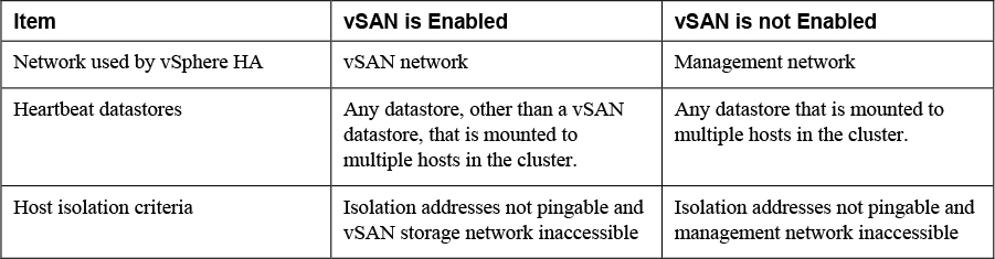
When reviewing each SDRS Recommendation on the Storage SDRS tab in the vSphere Client, you can examine the information described in Table 11-6 and use it when deciding which recommendations to apply.
Table 11-6 SDRS Recommendations Details
You can use the following procedure to override the SDRS datastore cluster automation level per virtual machine.
Step 1. In the vSphere Client, right-click a datastore cluster in the inventory pane.
Step 2. Select Edit Settings. Select Virtual Machine Settings
Step 3. Select one of the following automation levels
• Default (Manual)
• Fully Automated
• Disabled
Step 4. Optional: select or deselect the Keep VMDKs together option.
Step 5. Click OK
You can use the following procedure to create an inter-VM anti-affinity rule (a rule where two or more virtual machines are placed on separate datastores).
Step 1. In the vSphere Client, right-click a datastore cluster in the inventory pane.
Step 2. Select Edit Settings.
Step 3. Select Rules > Add
Step 4. Provide a name and select Type to VM anti-affinity.
Step 5. Click Add.
Step 6. Click Select Virtual Machine.
Step 7. Select at least two virtual machines and click OK.
Step 8. Click OK to save the rule.
To create an intra-VM anti-affinity rule (a rule each virtual disk for a specific virtual machine are placed on separate datastores), use a similar procedure, except set Type to VMDK-Affinity and select the appropriate virtual machine and virtual disks.
Configure and Manage SIOC
Storage I/O Control (SIOC) allows you to prioritize storage access during periods of contention, ensuring the more critical virtual machines obtain more I/O than less critical VMs. Once SIOC has been enabled on a datastore, ESXi hosts monitor the storage device latency. If the latency exceeds a predetermined threshold, the datastore is determined to be under contention, and every virtual machine that resides on that datastore is assigned I/O resources based on their individual share values. You can enable SIOC in three steps:
Step 1. In the vSphere Client, select a datastore in the Storage inventory view.
Step 2. Select the Configuration tab > Properties
Step 3. Click the Enabled check box under Storage I/O Control and click Close.
Note
SIOC is enabled automatically on Storage DRS enabled datastore clusters.
In addition to share values, which are similar to shares defined for CPU and memory, storage I/O limits can be defined on individual virtual machines to limit the number of I/O operations per second, or IOPS. By default, just like with CPU and memory resources, there are no limits set for virtual machines. In virtual machines with more than one virtual disk, limits must be set on all of the virtual disks for that VM. If you do not set a limit on all of the virtual disks, then the limit won’t be enforced. To view the shares and limits assigned to virtual machines, you can use the vSphere Client, to select a datastore, select the Virtual Machines tab, and examine the associated virtual machines. The details for each virtual machine includes its respective shares, IOPS limit, and the percentage of shares for that datastore.
Set SIOC Shares and Limits
As with CPU and memory shares, SIOC shares establish a relative priority in the event of contention. In the event of storage contention, virtual machines with more shares will observe more disk I/O than a virtual machine with fewer shares. The following procedure outlines how you configure SIOC shares and limits for virtual machines.
![]()
Step 1. From the vSphere Client, right-click a virtual machine in the inventory pane.
Step 2. Select Edit Settings.
Step 3. Expand one of the hard disks (for example, Hard disk 1).
Step 4. Select the drop-down menu next to Shares to define High, Normal, Low, or Custom share values.
Step 5. Select the drop-down menu next to Limit – IOPs. There is no limit set by default, but can change this to Low (500), Normal (1000), or High (2000), or Custom and enter a custom value for the IOPs limit.
Step 6. Click OK to save your changes.
Monitor SIOC Shares
To view the impact of shares on individual datastores, in the vSphere Client, select a datastore in the inventory pane, select the Performance tab and select View > Performance. Here, you can observe the following data.
• Average latency and aggregated IOPS
• Host latency
• Host queue depth
• Host read/write IOPS
• Virtual machine disk read/write latency
• Virtual machine disk read/write IOPS
SIOC Threshold
The default threshold for SIOC to begin prioritizing I/O based on shares is 30 ms, and typically does not need to be modified. However, you can modify this threshold if you need to. Be aware that SIOC will not function properly unless all of the datastores that share drive spindles have the same threshold defined. If you set the value too low, shares will enforce priority of resources sooner but could decrease aggregated throughput, and if you set it too high, might result in higher aggregated throughput, but less prioritization of disk I/O.
The following procedure will allow you to modify the threshold.
Step 1. In the vSphere Client, Storage inventory view, select a datastore and select the Configuration tab.
Step 2. Select Properties and under Storage I/O Control, select Enabled if it is not already.
Step 3. Click Advanced to modify the threshold for contention (this value must be between 10 ms and 100 ms)
Step 4. Click OK and select Close.
The procedure to reset the threshold to the default is similar:
Step 1. In the vSphere Client, Storage inventory view, select a datastore and select the Configuration tab.
Step 2. Select Properties and under Storage I/O Control, select Advanced.
Step 3. Click Reset.
Step 4. Click OK and select Close.
NVMe and PMEM
The following sections provide detail on configuring and managing non-volatile memory express (NVMe)
Manage VMware NVMe
As described in Chapter 2, non-volatile memory express (NVMe) devices are a high-performance alternative to SCSI storage. There are three mechanisms for NVMe: NVMe over PCIe, NVMe over remote direct memory access (RDMA), and NVMe over Fibre Channel (FC-NVMe). NVMe over PCIe is for local storage and NVMe over fabrics (NVMe-oF) is for connected storage. FC-NVMe is shared NVMe-oF storage using fibre channel transport. NVMe over RDMA is shared NVMe-oF storage using RDMA over Converged Ethernet v2 (RoCE v2) transport. Chapter 2 provides the requirements for each of these mechanisms.
After installing the hardware for NVMe over PCIe, ESXi detects it as a storage adapter that uses PCIe. You can use the vSphere Client to view the storage adapter and storage device details. No other configuration is needed.
NVMe over Fabrics Shared Storage
When using NVMe storage for shared storage, you must not mix transport types to the same namespace. You should ensure the active paths are presented, because they cannot be registered until the path has been discovered.
Table 11-7 identifies additional information about NVMe over Fabric versus SCSI over Fabric storage:
Table 11-7 SCSI over Fabric and NVMe over Fabric comparison.

To use FC-NVMe, you must add an appropriate, supported adapter, then use the following procedure to add the controller to the host.
Step 1. In the vSphere Client, select the host in the inventory pane
Step 2. Navigate to Configure > Storage > Storage Adapters
Step 3. Click Controllers > Add Controller.
Step 4. Select one of the following options.
a. Automatically discover controllers: Click Discover controllers and select a controller.
b. Enter Controller Details Manually: Provide the Subsystem NQN, the worldwide node name, and worldwide port name. Optionally, provide an Admin queue size and Keepalive timeout.
Configure ESXi to Support RDMA
You can configure an ESXi 7.0 host to access shared NVMe devices using RDMA over Converged Ethernet (RoCE) version 2 protocol. The host must have a network adapter that supports RoCE v2 and you must configure a software NVMe over RDMA adapter.
For hosts with a NIC supporting RoCE v2, the vSphere Client shows both the network adapter component and the RDMA component. You can select the host in inventory pane and navigate to Configure > Networking > RDMA Adapters. Here you can see the unique names assigned to each RDMA device, such as vmrdma0. For each device, you can see its Paired Uplink (its integrated NIC, such as vmnic9). To complete the host configuration, you can use the following procedure.
Step 1. Create a new VMkernel virtual network adapter on a vSphere standard or distributed switch and configure its uplink to use the RDMA paired uplink (for example, vmnic9).
Step 2. Select the host and navigate to Configure > Networking > RDMA Adapters.
Step 3. Select the appropriate RDMA device (for example, vmrdma0) and select VMkernel adapters bindings in the details pane.
Step 4. Verify that the new VMkernel adapter (for example, vmk2) appears.
Step 5. Select the host and navigate to Configure > Storage > Storage Adapters.
Step 6. Click the Add Software Adapter button.
Step 7. Select Add software NVMe over RDMA adapter.
Step 8. Select the appropriate RDMA adapter (for example, vmrdma0) and click OK.
Step 9. In the list of storage adapters, identify the new adapter in the category VMware NVME over RDMA Storage Adapter and make note of its assigned device number (for example, vmhba71).
Step 10. To identity the available storage devices, select the storage adapter (for example, vmhba71) and select Devices in the details pane. You can use these devices to create VMFS datastores.
Configure HPP
As described in Chapter 2, High-Performance Plug-in (HPP) is the default plug-in that claims NVMe-oF targets. NVMe over PCIe targets default to the VMware native multipathing plugin (NMP). You can use the esxcli storage core claimrule add command to change the claiming plugin in your environment. For example to set a local device to be claimed by HPP, use the --pci-vendor-id parameter and set the --plugin parameter to HPP. To change the claimrule based on an NVMe controller model, use the --nvme-controller-model parameter.
To assign a specific HPP Path Selection Scheme (PSS) to a specific device, you can use the esxcli storage hpp device set command with -pss parameter to specify the scheme and the --device parameter to specify the device. The available HPP PSS options are explained in Chapter 2, Table 2-6. To create a claim rule that assigns the HPP PSS by vendor and model, you can use esxcli storage core claimrule add with the -V (vendor), -M (model), -P (plugin), and --config-string parameters. In the value for --config-string, specify the PSS name and other settings, such as “pss=LB-Latency,latency-eval-time=40000”
Note
Enabling HPP on PXE booted ESXi hosts is not supported.
After using these commands, you should reboot the hosts to apply the changes.
Manage PMEM
PMem devices are non-volatile dual in-line memory modules (NVDIMMs) on the ESXi host which reside in normal memory slots. They are non-volatile and combine the performance of volatile memory with the persistence of storage. PMem devices are supported on ESXi 6.7 and later.
ESXi hosts detect local PMem devices and expos the devices as host-local PMem datastores to virtual machines. Virtual machines can directly access and utilize them as either memory (virtual NVDIMM) or storage (PMem hard disks). ESXi hosts can only have one PMem datastore, but it can be made up of multiple PMem modules.
Virtual PMem (vPMem)
In this mode, a virtual machine can directly access PMem resources use the resources as regular memory. The virtual machine uses NVDIMMs that represent physical PMem regions. Each virtual machine can have up to 64 virtual NVDIMM devices, and each NVDIMM device is stored in the host-local PMem datastore. Virtual machines must be at hardware version 14, and the guest OS must be PMem-aware.
Virtual PMem Disks (vPMemDisk)
In this mode, a virtual machine cannot directly access the PMem resources. You must add a virtual PMem disk to the virtual machine. A virtual PMem disk is a regular virtual disk that is assigned a PMem Storage Policy forcing it to be placed on a host-local PMem datastore. This mode has no virtual machine hardware or operating system requirements.
PMem Datastore Structure
The following are components of the PMem structure on an ESXi host:
• Modules: these are the physical NVDIMMs that reside on the motherboard.
• Interleave sets: these are logical groupings of one or more modules. ESXi hosts read from an interleave set in turns, so if there are two modules on an ESXi host, they will be read in parallel. You can identify the way the NVDIMMs are grouped into interleave sets via the vSphere Client.
• Namespaces: PMem datastores are built on top of namespaces, which are regions of contiguously addressed memory ranges.
To view information about the PMem modules, interleave sets, and namespaces, you can follow the following procedure:
Step 1. In the vSphere Host Client, select Storage from the inventory pane.
Step 2. Click on the Persistent Memory tab.
Step 3. Click Modules to see the NVDIMMs that contribute to the PMem datastore.
Step 4. Click Namespaces to see namespace information.
Step 5. Click Interleave sets to see how the modules are grouped into interleave sets.
To delete namespaces that were created by an operating system that was previously installed on the host machine, you can use the previous procedure to navigate to Namespace, select the namespace and click Delete. This frees up the PMem space, but you must reboot the host to access it.
Multipathing, Storage Policies, and vVOLS
This section provides information for managing storage multipathing, storage policies, and virtual volumes (vVOLs) in vSphere 7.0.
Manage Multipathing
As explained in Chapter 2, ESXi uses a pluggable storage architecture (PSA) that allows plugins to claim storage devices. The plugins include the native multipathing plugin (NMP), the High-Performance Plug-in (HPP), and third-party multipathing modules (MPPs).
ESXCLI Commands for Multipathing
You can use esxcli commands to manage the PSA plugins. For example, you can use the following command from an ESXi shell to view the multipathing modules (plugins).
esxcli storage core plugin list –plugin-class=MP
You can use the following command to list all devices controlled by the NMP module. For each device, you will find details, such as assigned storage array type (SATP) and the path selection policy (PSP).
esxcli storage nmp device list
To see details for a specific device, you can provide the --device option with the previous command. For example, if you have a device that is identified by mpx.vmbha0:C0:T0:L0, then you can use the following command to retrieve details for just that device.
esxcli storage nmp device list --device=mpx.vmbha0:C0:T0:L0
Table 11-8 provides information for some other esxcli commands that you can use with NMP.
Table 11-8 ESXLI Commands for NMP
Note
In many cases, the storage system provides ESXi with the storage device names and identifiers, which are unique and based on storage standards. Each identifier uses a naa.xxx, eui.xxx, or t10.xxx format. Otherwise, the host generates an identifier in the form of mpx.path, where path is the first path to the device, such as mpx.vmhba1:C0:T1:L3.
Likewise, Table 11-9 provides information for some esxcli commands that you can use with HPP.
Table 11-9 ESXCLI Commands for HPP
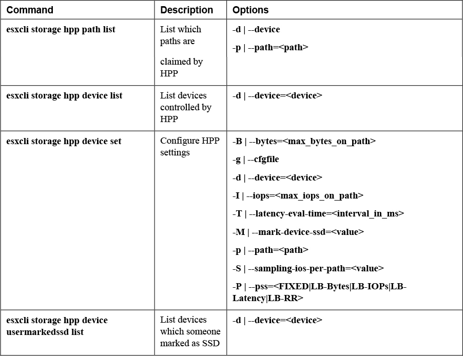
Managing Paths with the vSphere Client
This section provides information on using the vSphere Client to manipulate the path selection policy and available paths for NMP. For information on selecting Path Selection Schemes (PSS) for HPP, see the Configure NVMe and HPP section in this chapter.
A path to a storage device is represented as the storage adapter, storage channel number, the target number, and LUN number (the LUN position within the target) set that is used to connect to the device. For example, vmhba1:C0:T1:L3 indicates that the path uses storage adapter vmhba1, channel 0, Target 1, and LUN 3. To view the storage paths for a specific device, you can use the following procedure.
Step 1. In the vSphere Client, select a host in the inventory pane.
Step 2. Navigate to Configure > Storage > Storage Devices
Step 3. Select the storage device.
Step 4. Click the Properties tab and review the details. For NMP devices, the details include the assigned SATP and PSP.
Step 5. Click Paths and review the available paths to the device. The status for each path can be Active (I/O), Standby, Disabled, or Dead. For devices using the Fixed path policy, an asterisk (*) represents the preferred path.
To disable a path to a storage device, you can follow the previous procedure, select a path, and choose Disable.
In the vSphere Client, you can select a VMFS datastore and navigate to Configure > Connectivity and Multipathing to review path information to the storage devices backing the datastore.
To change the PSP that is assigned to a storage device, you can navigate to the device’s Properties page (see the previous procedure) and click Edit Multipathing. On the multipathing page, you can choose a policy, such as VMW_PSP_FIXED, VMW_PSP_RR, or VMW_PSP_MRU as described in Chapter 2, Table 2-11.
Manage Claim Rules
ESXi uses claim rules to determine which multipathing module owns the paths to a specific storage device and the type of multipathing support that is applied. Core claim rules determine which multipathing module (NMP, HPP, or a third-party module) claims a device. For NMP, SATP claim rules determine which SATP submodule claim the device. Table 11-10 describes a few commands for claim rules.
Table 11-10 Sample Claim Rules Commands

Manage Storage Policies
In vSphere, storage policy-based management (SPBM) can be used to align storage with application demands of your virtual machines. With SPBM, you can assign a storage policy to a virtual machine to control the type of storage that can be used by the virtual machine and how the virtual machine is placed on the storage. You can apply a storage policy as you create, clone, or migrate a virtual machine.
Prior to creating virtual machine storage policies, you must populate the VM Storage Policy interface with information about storage entities and data services in your storage environment. When available, you can use a vSphere APIs for Storage Awareness (VASA) provider to provide the information. Alternatively, you can use datastore tags.
To use storage policies, there are multiple steps required depending on the type of storage or services which you need. The following procedure contains the major steps.
![]()
Step 1. Populate VM Storage Policies: in many cases, this will populate automatically. However, you can manually assign tags to datastores:
a. Create a category for the storage tags:
i. From the vSphere Client, select Home > Tags & Custom Attributes
ii. Click Tags > Categories
iii. Click Add Category
iv. Define the following:
1. Category Name
2. Description
3. Tags Per Object
4. Associable Object Types.
v. Click OK.
b. Create a storage tag:
vi. Click Tags on the Tags tab.
vii. Click Add Tag
viii. Define the tag properties:
1. Name
2. Description
3. Category
ix. Click OK.
c. Apply the tag to the datastore:
x. From the storage inventory view, right-click the datastore.
xi. Select Tags & Custom Attributes > Assign Tag.
xii. Select a tag from the list and click Assign.
Step 2. Create a VM storage policy:
a. For Host-based services:
xiii. From the vSphere Client, select Home > Policies and Profiles
xiv. Click VM Storage Policies
xv. Select Create VM Storage Policy
xvi. Provide the following information:
1. vCenter Server
2. Name
3. Description
xvii. On Policy structure page:
1. Select the tab for the data service category
2. Define custom rules
xviii. Review the datastores that match the policy
xix. Review the settings and click Finish.
b. For vVols:
xx. From the vSphere Client, select Home > Policies and Profiles
xxi. Click VM Storage Policies
xxii. Select Create VM Storage Policy
xxiii. Provide the following information:
1. vCenter Server
2. Name
3. Description
xxiv. On Policy structure page, enable rules.
xxv. On Virtual Volumes rules set storage placement rules:
1. Select the Placement tab > Add rule
2. At Add Rule drop-down, define the available capacity.
3. Click Tags to define tag-based rules
xxvi. Set rules for datastore-specific services (optional).
xxvii. On the Storage compatibility page, review the datastores matching the policy
xxviii. On the Review and finish page, verify the settings and click Finish.
c. For Tag-based placement:
xxix. From the vSphere Client, select Home > Policies and Profiles
xxx. Click VM Storage Policies
xxxi. Select Create VM Storage Policy
xxxii. Provide the following information:
1. vCenter Server
2. Name
3. Description
xxxiii. On Policy structure page, enable rules.
1. Select Add Tag Rule and define the following:
a. Tag category
b. Usage option
c. Tags
2. Repeat as needed.
xxxiv. Review the datastores that match the policy.
xxxv. Verify the policy settings on the Review and finish page and click Finish.
VASA: Register a Storage Provider
To collect storage entities and data services information from a VASA storage provider, you can use the following procedure.
Step 1. In the vSphere Client, select vCenter in the inventory pane.
Step 2. Navigate to Configure > Storage Providers
Step 3. Click the Add icon.
Step 4. Provide the connection information for the provider with name, URL, and credentials.
Step 5. Select one of the following security methods:
a. Select the Use storage provider certificate option and define the location of the certificate.
b. Review and accept the displayed certificate thumbprint is displayed.
Step 6. Storage provider adds the vCenter certificate to the truststore when the vCenter server initially connects to the storage device.
Step 7. Click OK.
VASA: Manage Storage Providers
To perform management operations involving a storage provider, such as rescanning, you can use the following procedure.
Step 1. In the vSphere Client, select vCenter in the inventory pane.
Step 2. Navigate to Configure > Storage Providers
Step 3. Select a storage provider and choose one of the following options.
• Synchronize Storage Providers: Synchronizes vCenter Server with information for all storage providers.
• Rescan: Synchronizes vCenter Server with information from a specific storage provider.
• Remove: Unregisters a specific storage provider, which is useful whenever upgrading a storage provider to a later VASA version requires you to unregister and reregister.
• Refresh Certificate: Refreshes a certificate before it retires.
Apply Storage Policies to VMs
When performing a provisioning, cloning, or migration operation for a virtual machine you can assign a storage policy. For example, when using the New Virtual Machine wizard, on the Select Storage page, you can select a policy in the VM Storage Policy drop-down menu to assign a storage policy to the entire virtual machine. After selecting the policy, you should choose a datastore from the list of Compatible Datastores. If you use the replication service provided with vVols, you should either specify a preconfigured replication group or choose to have vVols create an automatic replication group.
Optionally, you can set different storage policies for each virtual disk. For example, on the Customize Hardware page you can select New hard disk and set a VM storage policy for that disk.
To change the storage policy assigned to a virtual machine, you can use the following procedure.
Step 1. In the vSphere Client, navigate to Menu > Policies and Profiles > VM Storage Policies.
Step 2. Select a storage policy and click VM Compliance.
Step 3. Select a virtual machine that is currently assigned the select policy.
Step 4. Click Configure > Policies
Step 5. Click Edit VM Storage Policies
Step 6. Assign the appropriate policy to the virtual machine or separate policies to each virtual disk.
Step 7. If you use the replication service provided with vVols, configure the replication group.
Step 8. Click OK.
Configure and Manage vVols
To use vVols, you must ensure that your storage and vSphere environment are properly configured.
To work with vVols. the storage system use must support vVols and must integrate with the vSphere using VASA. You should apply the following guidelines.
• The storage system must support thin provisioning and snapshotting.
• Deploy the VASA storage provider.
• Configure the following components on the storage side.
• Protocol endpoints
• Storage containers
• Storage profiles
• Replication configurations if you plan to use vVols with replication
• Follow appropriate setup guidelines for the type of storage you use, Fibre Channel, FCoE, iSCSI, or NFS. If necessary, install and configure storage adapters on your ESXi hosts
• Use NTP to ensure time synchronization among the storage system components and vSphere.
To configure vVols, you can use the following procedure.
Step 1. Register the storage providers for vVols, as described previously.
Step 2. Create a vVols datastore by using the following steps:
a. In the vSphere Client, right-click a host, cluster, or data center in the inventory pane.
b. Select Storage > New Datastore
c. Select vVol as the datastore type
d. Select the hosts that will access the datastore.
e. Click Finish.
Step 3. Navigate to Storage > Protocol Endpoints to examine and manage the protocol endpoints. Optionally, you can take the following steps:
a. Use the Properties tab to modify the multipathing policy.
b. Use the Paths tab to change the path selection policy, disable paths, and enable paths.
Exam Preparation Tasks
As mentioned in the section “How to Use This Book” in the Introduction, you have a couple of choices for exam preparation: the exercises here, Chapter 15, “Final Preparation,” and the exam simulation questions on the companion website.
Review All Key Topics
Review the most important topics in this chapter, noted with the Key Topics icon in the outer margin of the page. Table 11-12 lists a reference of these key topics and the page numbers on which each is found.
![]()
Table 11-12 Key Topics for Chapter 11

Complete Tables and Lists from Memory
Print a copy of Appendix B, “Memory Tables” (found on the companion website), or at least the section for this chapter, and complete the tables and lists from memory. Appendix C, “Memory Tables Answer Key,” also on the companion website includes completed tables and lists to check your work.
Define Key Terms
Define the following key terms from this chapter and check your answers in the glossary:
Non-volatile memory express (NVMe) devices
High-Performance Plug-in (HPP)
Review Questions
1. You are implementing encryption for a vSAN cluster in vSphere 7.0. Which one of the following options is a requirement?
a. KMIP 1.0
b. Deploy the KMS as a virtual machine in the vSAN datastore
c. Ensure the KMS is in vSphere Compatibility Matrix
d. Ensure the witness host participates in encryption.
2. You want to save space in your vSAN cluster by removing redundant data blocks. Which of the following steps should you take?
a. Enable Compression
b. Enable Deduplication
c. Enable Deduplication and Compression
d. Enable Allow Reduced Redundancy
3. In your vSphere 7.0 environment, you are using the Datastore Browser to perform administrative tasks. Which one of the following options is not available in the Datastore Browser?
a. Upload files
b. Download
c. Mount
d. Inflate
4. For your vSphere 7.0 environment, you are comparing NVMe-oF with SCSI over Fibre Channel. Which one of the following statements is true?
a. vVols are supported with NVMe-oF
b. SCSI-2 reservations are supported with NVMe-oF
c. RDMs are supported with NVMe-oF
d. HPP is supported with NVMe-oF
5. You are using the vSphere Client to manage the Storage Providers. Which one of the following is not an option?
a. Replace
b. Synchronize Storage Providers
c. Rescan
d. Refresh Certificate