

© 2006 by Ralph W. Lambrecht, all rights reserved
Equipment and Facilities
Image-Taking Equipment
The photographer’s tools of the trade
We both draw pleasure from making photographs with well-designed and well-maintained equipment. Between us, we have used at some time or other most 35mm, medium-format and large-format cameras, the makes and models of which are largely irrelevant. We do, however, have a few items that we both consider indispensable for capable and reliable picture making. What follows is an introduction to the fundamental tools, together with a discussion and some practical advice on equipment selection and testing.
Cameras and Film Formats
The camera is the most fundamental tool of every photographer. What started many centuries ago as a darkened room (camera obscura), simply providing an environment dark enough to observe a faint pinhole image, has turned into a rather sophisticated piece of image-taking equipment. As early as the 15th century, artists had substituted a small wooden box for the full-size room and later fitted it with a light-gathering lens (camera lucida). The inventors of photography simply replaced the copy screen of the camera lucida with a light-sensitive material to capture their images. Since then, modern cameras have matured to include a long list of features, which include the protection, accurate positioning and smooth transportation of film, firm attachments for fixed or exchangeable lenses, bright viewfinders for image composition, manual or automatic focusing aids, precise control of exposure time and/or lens aperture and sophisticated software to automatically calculate the ‘optimum’ exposure for each subject.
There are so many different cameras available today that it is often difficult to decide which camera to select for one’s own photography. In this book, we limit our view to cameras that are likely to have the feature set and quality required by serious amateurs or professional fine-art photographers, well aware that it is impossible to make a meaningful camera recommendation without knowing the photographer’s circumstances and photographic requirements. There is no such thing as one ‘best’ camera. The camera is a tool, and different photographic situations require different tools. Nevertheless, one common way to narrow down the selection is to categorize cameras by their film format. Broadly speaking, there are three groups: small-, medium- and large-format cameras.


fig.1 The film-based Nikon FM (a) from 1977, the digital Nikon D3x (b) from 2008 and the rangefinder Leica M6 on the previous page are all examples of 35mm cameras. They are ideal for travel, reportage, news, sports and candid street photography, or any other area of photography where speed and portability are more important than ultimate image quality.
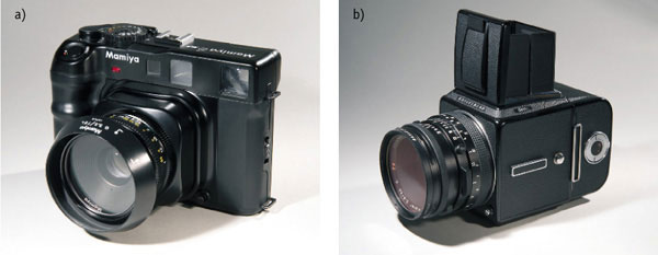
fig.2 The rangefinder Mamiya 6 and the Hasselblad 501C SLR are high-quality medium-format cameras. The Hasselblad is ideal for portrait, fashion and model photography, whereas the Mamiya is a good choice for the travelling photographer. Due to its retractable lens mount, the Mamiya does not need much more space than a 35mm SLR but offers the benefits of a medium-format negative.
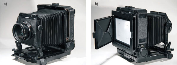
fig.3 The Toyo 4x5-inch metal-field view camera has the typical features of a large-format camera. Compared to the other cameras, large-format cameras are heavy, bulky and very rudimentary. At first glance, they seem like a remnant of the past, but a large-format camera is the ideal tool for architectural and landscape photography or whenever ultimate image quality cannot be compromised.
Small-Format
All cameras that produce image sizes of up to 24x36 mm on 35mm roll film are small-format cameras (fig.1). The 35mm film format (fig.4) was initially created in 1892 as a motion picture film with an image size of 18x24 mm, and was adapted as early as 1908 for still cameras with an image size of 24x36 mm. Since the late 1960s, when it started to outsell 120 roll film, 35mm (FX) has been the world’s most popular photographic film format. However, it took until the introduction of the first Leica in 1925 for the 24x36 mm format on 35mm roll film to reach global acceptance.
A modern high-quality 35mm lens has more resolving power than any other film-format lens, but the image quality of a 35mm negative is still limited by its small size. For example, to fill an 8x10-inch print without cropping requires an 8.5x enlargement, and such an enlargement will definitely reveal some non-image negative detail to the naked eye. On the other hand, due to the popularity of this film format, an enormous range of lenses and accessories is available for 35mm cameras, more than for any other film format.
The strengths of this format include its speed of operation, its versatility and its portability. All this makes the 35mm format a prime choice for travel, reportage, news, sports and candid street photography, or any other area of photography where speed and weight are more important than ultimate image quality.
Medium-Format
All cameras that use 120 roll film are medium-format cameras (fig.2). Kodak introduced the 120 roll film in 1901 for the Brownie No.2, and it survives to this day as the most popular medium-format film ever. 120 roll film consists of the actual film material and a slightly wider and longer backing paper. The film is taped to the black backing paper at the leading edge, and together, they are wound onto a spool. The paper protects the emulsion from light and facilitates film transport and accurate negative spacing.
120 roll film is used for a variety of medium-formats, all limited by the film’s width but varying in size along the film’s length. The most popular medium-format negative sizes are shown in fig.4. Largely due to the increase in negative size, moving up from 35mm film to medium format improves image quality significantly. Most medium-format optics deliver excellent contrast and resolution, and the increase in negative size allows for much smaller enlargement to get to the same size print. For example, to fill an 8x10-inch print without cropping requires only about half the magnification of a 35mm negative, which will hide most non-image negative detail from the observer.
Medium-format cameras produce high-quality images without being too bulky or heavy. They are not as portable as 35mm cameras, and many are missing modern conveniences such as auto-focus and zoom lenses, while some are limited to only a few lens choices. However, medium-format cameras are a prime choice for portrait, fashion and model photography. Medium-format rangefinder cameras are also a good alternative for large-format landscape photographers, because the difference between a medium and a large-format print is often hard to tell.

fig.4 Common film formats differ significantly in surface area. The larger the negative, the less enlargement is required to produce the same size print. When small negatives are enlarged 8x or more, non-image negative detail becomes obvious to the human eye, and print clarity is reduced. When it comes to image quality, there is no substitute for a large negative.
Large-Format
All view cameras that use 4x5-inch (or larger) sheet film are large-format cameras (fig.3). Large-format cameras have been around since the beginning of photography. The most common format is 4x5 inches (fig.4). Less common formats are 5x7, 8x10, 11x14, 16x20, and 20x24 inches. 4x5 cameras were very popular with press photographers until the mid 1940s, when more convenient medium-format and 35mm cameras became favored.
Compared to the other film formats, large-format cameras are heavy, bulky and very rudimentary. At first glance, they seem like a remnant of the past. A number of actions are required to take a single photograph: the camera must be set up on a tripod, a film holder must be loaded in the dark with single sheets of film, the scene must be composed on the camera’s ground glass and the film holder must be fitted to the camera back prior to exposure. However, sometimes this is all well worth the effort, because large-format images are of exceptional quality. In addition, most large-format cameras have adjustable front and back standards, which allow for a better control of perspective and depth of field. A large-format camera is the ideal tool for architectural and landscape photography or wherever the very best image quality is required.
Lenses, Shutters and Apertures
The image-creating capabilities of a photographic lens makes it the centerpiece of our image-taking equipment. Lenses demote everything else in our camera bag to the secondary role of merely supporting the photographic process. A photographic lens can be as simple as a tiny hole in a piece of metal foil that provides a fixed aperture for pinhole photography. Or, it can be as complex as a compound lens, made of a series of smoothly polished concave and convex pieces of specially coated glass to correct, as much as physically possible, the many optical aberrations that are inherent in a single lens.

fig.5 Camera-lens designs differ with film format. (top) 35mm lenses are camera-brand dedicated and come as fixed-focal or zoom lenses. (center) Medium-format lenses are also dedicated to a camera brand, but zoom lenses are rare. (bottom) Large-format lenses are interchangeable between camera manufacturers.
Fig.5 shows a variety of advanced photographic lens designs for different film formats. Sophisticated 35mm lenses come as fixed-focal or zoom lenses. They incorporate an iris diaphragm, providing an aperture adjustment mechanism, in 1/2 or 1-stop increments, and feature a manual or automatic cam system, sliding the lens elements into focus at any distance. Some 35mm lenses also include a leaf shutter, but in most 35mm cameras, timing the exposure is left to a focal-plane shutter in the camera body. Like 35mm lenses, most medium-format lenses (center) are dedicated to one brand of camera. Some incorporate a leaf shutter (Hasselblad 500 Series, right), others don’t, because a focal-plane shutter is built into the camera body (Mamiya 6, left). The aperture ring is usually adjustable in 1/2 or 1-stop increments. Zoom and autofocus lenses are available for medium-format cameras, but they are not as common as they are for 35mm cameras. Large-format lenses have the benefit of being camera independent. One must take care that their image circle is large enough to illuminate the entire negative format, but any 4x5 lens will work on any 4x5 camera, by simply mounting the lens on a camera-dedicated lens plate. All large-format lenses have a built-in aperture diaphragm, adjustable in 1/3 stops, and are mounted into separately available leaf-shutters. There are no autofocus or zoom lenses available for large-format photography, but some lens designs allow modifying the focal length by simply replacing the rear lens element with another.
A list of typical lens-selection criteria includes focal length or range, maximum and minimum apertures, design, weight, advanced features, price and most importantly the optical quality of the lens. With modern lenses, the price is largely influenced by quality, but it also depends heavily on design complexity and advanced features, like autofocus or vibration reduction. As a general rule, lenses for rangefinder cameras are easier to design than lenses for SLRs, where the required packaging space for the mirror necessitates optical compromises. Consequently, rangefinder lenses are typically better than SLR lenses, which is especially true for wide-angle lenses. Similarly, fixed-focal lenses have a rather straightforward design, compared to zoom lenses, and are not as challenging to manufacture as their variable focal-length counterparts. They also typically have larger maximum apertures, and that’s why many photographers still insist that their fixed-focal length lenses are of superior optical quality and have the edge over zoom lenses, in spite of advanced modern lens designs.
When working with fixed-focal lenses, it is sometimes difficult to pre-determine which focal length to choose for any given subject. Fig.6 illustrates a few visual clues to aid selection of the most appropriate focal length for any given subject, using only your arm and hands. The numerical values relate to 35mm focal lengths, when holding your hands at arm’s length, or your arm as far away from your body as anatomically possible.

fig.6 This illustration gives a few visual clues to aid selection of the most appropriate focal length for any given subject, using only your arm and hands. The numerical values relate to 35mm focal lengths, when holding your hands at arm’s length, or your arm as far away from your body as anatomically possible.

fig.7 A ‘normal’ lens is specified as having a focal length roughly identical to the negative-format diagonal. This computes to about 80 mm for a 6x6 medium-format camera. The angle of view for a normal lens is independent of negative format, but the focal length, achieving the same angle of view, differs with negative format. The angle of view (α) is given by the above equation, where ‘d’ is the dimension of the negative-format diagonal and ‘f’ is the focal length.
Photographers working with different negative formats sometimes struggle to find the equivalent focal length of a known lens in another format. The angle of view is identical between negative formats, but the focal length, achieving the same angle of view, differs with negative format. A ‘normal’ (normal-focus) lens is specified as having an angle of view of about 50° or a focal length roughly identical to the negative-format diagonal. This computes to about 45 mm for a 35mm camera, about 80 mm for a 6x6 medium-format camera and 300 mm for an 8x10 large-format camera. Fig.7 illustrates the relationship between the angle of view and the focal lengths of different negative formats. It also provides a convenient way to compare focal length between negative formats. For example, if you prefer a 85mm lens for 35mm portrait work, you will get a similar effect using a 300mm lens with a 4x5 camera.
We usually trust that lens apertures, in conjunction with shutters, flawlessly control the total amount of light received by the film. It is easy to overlook the fallibility of shutter and aperture mechanisms, but their usage and age do affect their mechanical performance. Metal blades wear, springs weaken and lubricants become sticky, all causing unwanted deviations in exposure. Even electronically controlled mechanism activation does not guarantee perfect performance forever. We must accept that the intricate mechanisms of lens apertures and shutters are subject to a certain amount of mechanical error.
Shutter Accuracy
With long exposures above 1 second, shutter accuracy is less significant to film exposure than film reciprocity failure. At the other timing extreme, fast shutter speeds push the mechanics to the limits of their capabilities, and here, even small inaccuracies become a significant cause for exposure errors.
The mechanics of a shutter are affected by extreme temperatures. In cold conditions, shutter lubricants become more viscous. This affects the shutter speed accuracy. The mechanism moves more slowly, causing overexposure. Working the shutter a few times before making an exposure will free up the mechanism and reduce the error. This technique is also helpful to improve the performance of shutters that have not been used for some time. Warm temperatures have the opposite effect with faster moving mechanics causing underexposure.

fig.8 Electronic shutter testers can be used to measure the effective shutter speeds of leaf and focal-plane shutters. Knowing the true shutter speed, the photographer can make the appropriate exposure adjustments, as long as the error is consistent and repeatable.
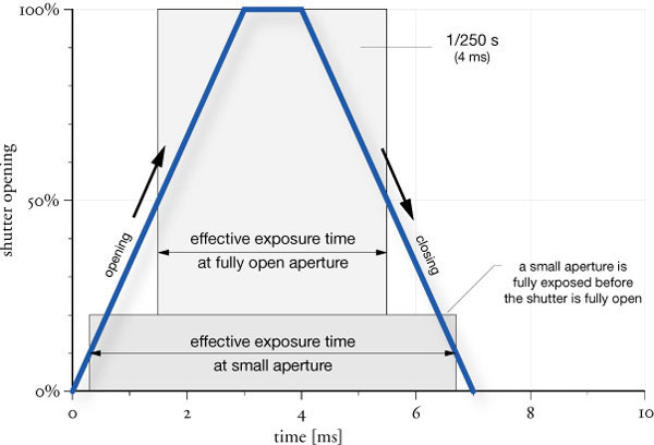
fig.9 Exposure starts as soon as the leaf shutter opens with a faint image and gets increasingly brighter until the shutter is open. The reverse takes place as the shutter closes. The exposure time marked on the shutter is the time from when the shutter is half open until it is half closed. The exposure contribution of an opening and closing shutter is minute at slow shutter speeds, but becomes significant at fast speeds, making for accurate exposure at wide-open aperture.

fig.10 A leaf shutter in combination with a small aperture and fast shutter speed increases effective exposure significantly. A small aperture hole is completely revealed by the shutter almost as soon as it opens and provides unobstructed exposure until just before it is fully closed. Consequently, as the aperture is made smaller, the effective exposure time becomes longer than the marked exposure time.
Thanks to modern electronics, shutter errors can be detected with test equipment similar to the shutter tester in fig.8. Shutter testers can be used to measure the effective shutter speeds of leaf and focal-plane shutters. This simple low-cost shutter tester was once sold by Calumet Photographic but is no longer available as new. Expensive professional models are still on the market, but at a price often beyond the average amateur’s budget. However, their functionality is based on the same technical principle, in which a light sensor triggers a digital counter as soon as the light level reaches a certain level. Alternatively, consult a good camera repair shop to have your shutters tested, or if you’re handy with electronic circuitry, take a look at the chapter ‘Make Your Own Shutter Tester’ for simple do-it-yourself instructions. Knowing the true shutter speed, the photographer can make the appropriate exposure adjustments, as long as the error is consistent and repeatable, but the equipment should be serviced by an authorized source for convenience or if errors are erratic and inconsistent.
Apart from mechanical errors, the effective exposure time of a leaf shutter, in combination with a small aperture and fast shutter speed, is significantly different from the marked exposure time. This can be explained by the interaction of the shutter and aperture. Prior to the exposure, the lens aperture blades are set to a fixed position providing an opening for the image forming light. At this point, the metal blades of the leaf shutter are blocking the light from entering. At the beginning of the exposure, the shutter blades open rapidly within 2-3 ms, but when the exposure is completed, they close just as quickly. Of course, film exposure starts as soon as the leaf shutter opens. Nevertheless, since leaf-shutter blades are very similar in construction to aperture diaphragm blades, the exposure starts with a faint image and gets increasingly brighter until the shutter is wide open. The reverse takes place as the shutter closes. To account for the exposure during opening and closing of the shutter, the exposure time marked on the shutter is the time from when the shutter is half open until it is half closed. Hence, the shutter is not marked with the total exposure time but with the effective exposure time. The exposure contribution of an opening and closing shutter is minute at slow shutter speeds, but becomes significant at fast speeds. Working with the effective exposure time, rather than total exposure time, makes for a more accurate exposure at wide-open apertures.
However, if a small aperture was chosen, the effective exposure time will be longer than expected. Figures 9 and 10 illustrate this unavoidable exposure error. A small aperture hole is completely revealed by the shutter almost as soon as it opens and just before it is fully closed. Consequently, as the shutter speed is increased and the aperture is made smaller, the effective exposure time becomes increasingly longer than the marked exposure time. This is particularly true of large-format lenses where apertures smaller than f/22 are common and exposure errors can be up to 1 stop. Luckily, the combination of fast shutter speeds and small apertures don’t occur very often in practical image making.

Photometric values for illumination ‘E’ and lumination ‘L’ can be calculated from any lightmeter measurement (aperture ‘N’ and exposure time ‘t’, or the exposure value ‘EV’) as long as the meter’s calibration constants for incident ‘C’ and reflected ‘K’ readings are known. Typical values range from 250-280 for ‘C’ and 12-15 for ‘K’, but individual values must be obtained from the manufacturer.
Aperture Accuracy
The lens aperture is a mechanical device, even when controlled by electronics. Aperture errors are caused by mechanical tolerances and sticky mechanisms. Like shutters, they are most likely to perform sluggishly in cold conditions and after long periods of non-use. In this case, work the aperture blades a few times before making the actual exposure.
Sticky aperture mechanisms also affect modern SLR cameras, which abruptly close the aperture to the set value before opening the shutter. If the diaphragm blades are unable to reach the chosen aperture in time, the opening will be larger than indicated when the shutter fires, causing overexposure.
It is possible to detect some defects by observation. With the camera facing you and using the stop down lever, close the aperture to its minimum setting. Inspect the opening, try to memorize its diameter and compare it to its closed size when firing the shutter, over a range of shutter speeds. The diaphragm should close to the same aperture in every case. If the camera is likely to be used in cold climate conditions, conduct the test outdoors on a cold day and with a cold camera. Any oil or grease on the diaphragm blades should be serviced at once.
In addition to the mechanical issues, maximum aperture extremes are often advertised with optimistic aperture values and provide uneven illumination, which ultimately leads to objectionable vignetting. The minimum aperture accuracy is more sensitive to mechanical tolerances. For these reasons, it is wise to avoid using extreme apertures and fast shutter speeds for material testing, even with cameras that have focal-plane shutters.

fig.11 Dedicated spotmeters are optimized for serious Zone System work. The Pentax Digital Spotmeter measures ambient, and the Minolta Spotmeter F both ambient and flashlight.
Lightmeters
Lightmeters are divided into two main categories, ‘reflected’ and ‘incident’ meters. A reflected lightmeter is designed to measure the light reflected from the subject, which is referred to as lumination. An incident lightmeter measures the light falling on the subject, which is illumination.
Some reflected lightmeters simply average all measurements from the full field of view, others give priority to the center or perform sophisticated, subject-dependent computations to propose the best film exposure. Another option is to use a dedicated spotmeter (fig.11), reading luminance only from a small area.
To use the Zone System seriously, a spotmeter is essential for measuring selected exposure values. Ideally, the meter should have a field of view of no more than 1° and a resolution of 1/3 stop or better. The models we have tried, which include those by Gossen, Minolta, Pentax and Sekonic, all have a unique color response, calibration and resistance to flare, making an overall recommendation more one of personal choice. Ralph prefers the Minolta meter for its fine resolution and the Pentax meter for its simplicity, Chris prefers the multi-functional Sekonic, since it measures reflected and incident light with ambient and flashlight.
Whichever meter you own, it will take some time to understand its limitations and obtain reliable exposure indications in a variety of situations. Accuracy is difficult to assess, but the color response and the meter’s resistance to flare can be evaluated quite easily. The chapter on film exposure discusses film and meter color sensitivity and the application of filters, to compensate for differences between the perceived and recorded subject brightness of different colored objects.
Flare Testing
In a perfect world, one should be able to measure small shadow areas without interference from adjacent light sources or bright white surfaces. Spotmeters are not perfect and, like cameras and lenses, suffer from flare. Flare can be crudely evaluated by measuring and exposing a photographic ‘black hole’ in close proximity to a bright white surface. A simple self-made box or a modified shoebox will suffice as a test target (fig.12). Take the box and paint the outside bright white and the inside flat black. Then, cut a 50mm (2-inch) hole into one side of the box and construct a shade, protecting the hole from direct light. Paint the inside of the shade flat black as well. Some light will still enter the box, and an extremely small fraction of it will be reflected back through the hole but not enough to create any density in the negative. We have successfully created a perfect ‘black hole’.

fig.12 The self-made flare test-box is painted bright white on the outside and flat black inside. The shaded opening provides a photographic ‘black hole’.
To estimate flare, place the box in daylight, with the black hole facing spotmeter and camera. Then, take an exposure reading of the hole from about 2.5 meters (8 feet), making sure that the spotmeter’s measuring area is entirely within the black hole. Any reading above the meter’s minimum is a measure of the flare generated inside the meter. Now, take an incident reading at the box and expose a piece of film accordingly. Any negative density in the hole is due to camera and lens flare, because the black hole does not provide any image-based exposure. Ideally, meter and camera flare should match, but if required, flare can be minimized by shielding meter and camera lens from any direct light source with the palm of your hand.
Incident Meters
An incident meter measures the light falling on the subject, averaging out all involved light sources and largely ignoring subject luminance (fig.13). Consequently, the reading of an incident meter is not influenced by subject brightness. For example, the reading due to bright sunlight falling on a dark barn door is identical to the same light falling on a white horse. Both subjects require the same exposure, for the barn door to appear as dark and the horse to appear as white as they really are. As long as the subject brightness range and the distribution are about normal, incident readings are simple, fast and accurate. Not surprisingly, that’s why incident meters are so popular with studio photographers.
Not much is published about using incident light meters for the Zone System, but they are a practical alternative to spotmeters in typical outdoor scenes. Their application relies on the fact that natural objects have an average subject reflectance range of about 5 stops. In other words, in perfectly diffuse lighting, a natural scene has a subject brightness range of about 5 stops. Consequently, we only need to know how the subject lighting ratio deviates from ‘0’, in order to determine the appropriate development scheme.
Two incident-meter readings, always pointing the meter’s dome towards the camera, are enough to determine Zone-System exposure and development time. First, take an incident reading in a shadow area of the subject, or shade it from the dominant light source. Note the reading, because it gives a literal rendition of the shadow-tone values and dictates the exposure. Take another reading in a brightly illuminated area of the subject, or expose it to the dominant light source. The difference between these two readings is a measure of the subject lighting ratio in stops.
The actual subject brightness range is the sum of the average natural subject reflectance range (5 stops) and the measured subject lighting ratio. Since we define a normal scene as having a 7-stop subject brightness range (pictorial range), a subject lighting ratio of 2 stop requires normal processing (N), 3 stops require N-1, 4 stops N-2 and so on. If the subject lighting is perfectly diffuse (no difference between the two readings), N+2 development is required in order to increase the negative contrast to the pictorial range.
Tripods, Heads and Plates
For architecture, landscape and studio photography, a decent camera support is essential. In most cases, any tripod is better than none, but one should choose with care and consideration between the many brands and designs available. Furthermore, the choice of tripod head is as important as the tripod itself, and it is often beneficial to mix and match designs regardless of manufacturer. Additionally, the choice of materials contributes to the final performance, and often a deciding factor is transportability. No tripod is less rigid than the one left at home, because it was too heavy.
We have used many brand-name tripod models between us, in a variety of materials and styles, from traditional aluminum models to modern carbon-fiber composite designs. Each model had its pros and cons. No design is optimal in every situation. Consider your photographic needs before you decide on a tripod, based on weight, size, working height, operation speed or rigidity.

fig.13 Incident meters are invaluable, especially in studio conditions. Both meters, shown here, measure ambient and flashlight. The Sekonic L-758D is also waterproof and features an integrated 1° spotmeter, making it a universal meter for field and studio work. In the absence of an incident meter, a reflectance reading off of a Kodak Gray Card will yield the same result.
Ralph prefers the traditional Manfrotto aluminum designs for their solid support in the field, and selected a professional studio stand for his indoor work (fig.14). Chris is more weight conscious and settled on two Gitzo carbon-fiber tripods (fig.15) instead of the aluminum models. These are incredibly light yet surprisingly rigid. Although carbon fiber is less robust than aluminum, with a little respect, it is fine for everyday use. The tubular carbon-fiber leg-and-clamp design also has remarkable vibration-damping properties. Chris favors two sizes, a large, 3-section version for studio and large-format work and a shorter, 4-section model for field trips with a 35mm or medium-format rangefinder camera. The larger model is modular, accepting a range of center-column styles with the option of dispensing with the column altogether for lightness and ultimate rigidity.
With any design, it is good practice to increase the height of the tripod by extending the legs, before raising the center column. This increases the tripod’s footprint and, consequently, its stability. Tripod stability is further increased by adding weights to lower column, legs or braces. A lightweight option is a rubber foot strap, which is attached to the lower column and simply stepped on during exposure.
Tripod Heads
Each material and joint in a tripod system affects the rigidity of the whole. The tripod head, often chosen for convenience, is arguably the most critical component in the tripod system. It is wise to evaluate models from other brands, since most use a standard 3/8 or 1/4-inch fixing thread. There are two main designs (see fig.16): ball-and-socket (B&S) and pan-and-tilt (P&T). Ralph uses P&T designs exclusively. Chris typically uses B&S heads for fieldwork and P&T heads for studio work. Each has been carefully chosen to ensure maximum rigidity through a combination of close tolerances, large contact surfaces and a low profile. Most heads are made from aluminum or magnesium alloy. Even though these materials are stiff, each arm, platform and bracket must be as short as possible to prevent a ‘spring-back effect’ under load. For instance, the otherwise versatile, off-center B&S heads are not ideal for medium-format or heavier cameras, in our opinion.
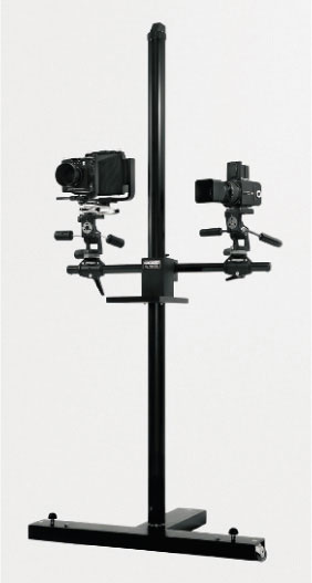
fig.14 A professional studio stand can handle all film formats and more than one camera at once.

fig.15 A rigid tripod serves most needs, from large-format studio work to fieldwork with smaller formats.

fig.16 The Arca Swiss ball-and-socket model is substantial enough for lightweight large-format cameras and is smooth and quick to operate. The traditional Manfrotto pan-and-tilt head is 550g heavier, with the strength for special applications, heavy loads and ultimate stability.

fig.17 The two Arca Swiss plates have bare aluminum bases and form a perfect mate to smooth bottomed cameras. The two Manfrotto plates are supplied with a soft rubber or cork mat. The smaller plate has had its mat changed to hard leather to reduce the compliance between camera and tripod.
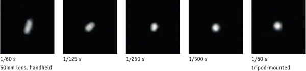
fig.18 To get the highest resolution possible, the use of a tripod is essential, and the rule-of-thumb, requiring nothing less than the reciprocal of the focal length as the maximum exposure time, is inadequate. Shown here, from left to right, are the results of photographing a point light source, at a distance of 5 m, with a handheld 50mm lens, at 1/60, 1/125, 1/250 and 1/500 of a second. The suggested time of 1/60 s is far from adequate. It took as little as 1/500 s to eliminate camera shake completely. But, the tripod-mounted camera delivered a perfect result at 1/60 of a second.
By design, a B&S head is at its optimum when the weight is directly above the pivot. Arca Swiss and other manufacturers have also realized that larger balls improve rigidity, especially in a tilted position. Their range of close tolerance B&S designs are world renown, and its progressive friction control is particularly welcome when manipulating an unwieldy camera.
Camera Plates
Last, but by no means least, is the method of camera attachment, called camera plates (see fig.17). Those varieties that rotate the support platform against the camera base are best avoided. They inevitably create scratches and, more importantly, may not grip sufficiently, especially if the camera base is not perfectly smooth. Our favored tripod heads use a separate quick-release camera plate, which is tightened to the camera base by means of a thumb wheel or coin-slotted screw head and then securely fastened or clipped to the head. This not only allows the photographer to change cameras quickly, but in the case of the many camera designs, it allows the photographer to use custom designed camera plates to prevent swiveling, avoid covering rewind buttons and to maximize the supported camera base area.
Soft Is Bad, Hard Is Good
Clearly, when it comes to tripod and head design, rigidity is important; yet, many camera plates are topped with a soft textured rubber or cork material, to grip and protect the camera base. A small improvement can be obtained when this is replaced with something less compliant, to increase rigidity and reduce nose-droop, especially on the smaller plates designed for SLRs. If your camera has a flat base, the best interface material is bare metal, but if the camera has to be used in a tilted position, a base-plate with a small anti-twist ridge or pin, like the middle camera plate in fig.17, solves the issue effectively, without the need for excessive tightening of the fixing screw. For those cameras with uneven bases (the Mamiya 6 and 7 have raised bumps on their base around the tripod bush), a little compliance prevents stressing the camera base-plate. A piece of hard leather, a scrap piece or an old coaster cut to size, is ideal and provides just enough give.
The effectiveness of a rigid camera support may be substantiated with a simple test. For the test sequence shown in fig.18, a 35mm SLR, fitted with a standard 50mm lens, was used to photograph a point light source from a 5m distance. A range of handheld shutter speeds is compared to a slow-speed tripod-mounted exposure. Contrary to common belief, it is impossible to get the best from our lenses unless a very short exposure or a solid tripod is used. It is pointless to mount premium glass on the front of the camera, unless similar care is taken with the camera support.
Flash Units May Harm Your Camera
Some photographers prefer to use available daylight exclusively and enjoy, for example, the beauty of a natural window light. Others would rather have the control and flexibility available from artificial lighting, which allows them to precisely model each lighting situation themselves. The trouble with available light is that it is not always available, or there is just not enough of it. Artificial lighting and flash units offer a creative alternative.
Flash lighting can be as simple as a small pocket flash gun or as elaborate as an entire studio lighting setup (see fig.19), but both pose the same potential danger to the electrical contacts that trigger the flash synchronization in cameras, lenses or shutters. According to ISO 10330:1992, all cameras are designed to accept trigger voltages of up to 24 volt. There are two compounding problems, however. Some cameras just cannot handle trigger voltages that high, and many flash units produce much higher voltages. The result is unexpected wear of the electrical contacts, or worse, a ‘fried’ camera, lens or shutter. Fortunately, the remedy is quite simple: Don’t attach flash units directly to your camera! Use a wireless radio flash trigger, consisting of a sender and receiver, for the first flash unit (fig.20a), and fire additional units with optical flash triggers or so-called ‘slaves’ (fig.20b).

fig.19 The trouble with available light is that it is not always available, or there is just not enough of it. Artificial lighting and flash units offer a creative alternative, but be careful, not every flash is as sensitive to your camera as this portable unit is from Hensel.
(image copyright Hensel, GmbH)

fig.20 A wireless radio flash trigger (a) is the safest way to trigger flash units regardless of size. The sender is directly attached to the camera, lens or shutter, and the receiver is connected to the first flash unit. Additional flash units can be fired with optical flash triggers (b) or so-called ‘slaves’. This way, high trigger voltages from the flash unit cannot harm the sensitive electrical contacts of the flash synchronization.
Quality, Accuracy and Resolution
It is worth considering that many purchases are made on the promise of quality and accuracy. The concept of quality is the combination of performing within design specifications and satisfying customer expectations. On the other hand, accuracy is the ability to perform with precision compared to a known standard. Both concepts are difficult to measure without specialized equipment, which requires certified calibration in regular intervals. Brand name and product price alone are no guarantee for accuracy, but a practical photographer is more interested in repeatability and resolution than absolute accuracy anyway.
The repeatability of camera, meter or darkroom equipment is perhaps the most important, as it enables the individual to make meaningful long-term use of their equipment, inviting comparison and consistency. The variation from day to day, or frame to frame can be measured using simple techniques. For example, an exposure of a test target taken outdoors on a cold day with cold equipment can be compared with that on the next frame taken with pre-warmed equipment.
Resolution is often advertised as an indicator of accuracy, but that is not necessarily the case. Resolution, within the context of this chapter, simply refers to the fineness of a meter reading, or the control over a shutter or an aperture setting. A meter with a resolution of 1/10 stop, but poorly adjusted, may be less accurate than one with 1/3-stop resolution that performs within manufacturing tolerances. For this reason, it is worth having your equipment checked periodically by a reliable source. This is especially true for meters and shutters.
Darkroom Design
Creating a practical and creative environment
Since publishing the previous edition, we have both changed our darkrooms in an attempt to improve the balance between domesticity and dedication. Together, we have designed and worked in about a dozen darkrooms over the years, always implementing the lessons learned from one design into the next. In this chapter, we highlight the basics of darkroom design and draw upon our personal experiences and solutions to address common issues.
Individual darkroom designs differ with photographic requirements, available floor space and frequency of use. Blending the darkroom into a domestic environment can be a challenge, but if designed well, it can be a haven from the perpetual demands of everyday life. On the other hand, an impractical and uncomfortable darkroom will not provide the creative atmosphere necessary to create a fine print.
The Room
All you need to set up a darkroom is a spare room or bit of available floor space. The basement is an ideal location as long as it has adequate ceiling height, because this area of the house experiences only minimal seasonal temperature fluctuations and typically offers easy access to heating, electricity and plumbing. Looking at the same criteria, attics and garages are less attractive candidates. The minimum floorspace requirements for a darkroom differ depending on maximum print size and printing equipment. Fig.1 and 2 illustrate two darkroom layouts, both designed to create prints up to 16x20 inches. The medium-size darkroom in fig.1 has separate dry and wet areas, and offers enough room for five trays as well as a large worktop. In fig.2, a vertical slot processor makes it possible to reduce darkroom dimensions to a minimum.

© 2000 by Steve Sherman, all rights reserved

fig.1 This medium-size darkroom has separate dry and wet areas, and offers enough room for five 16x20-inch trays as well as a large worktop.
Light Proofing
After an appropriate location for the new darkroom has been found, it must be completely shielded from external light sources to make the room totally dark. Initially, doors will be your main focus, because they must be light proofed while maintaining their intended functionality. Next come the windows, followed by air vents, suspended ceilings and any other potential sources of unwanted light. Continue until the last minute crack in the walls is plugged, and the room is completely lightproof.
Doors
Large club, community or commercial darkrooms must meet the need for people to freely move in and out of the room during the darkroom session without external light entering the room. This is why these darkrooms are typically fitted with revolving doors or an interlocking double-door system.
Given sufficient floor space, an open, light-trapping entrance is a more convenient alternative and costs less. The custom-built example in fig.3 provides easy room access without interrupting ongoing darkroom sessions for others. The inside walls of the light-trap are painted flat black, and an optional set of light curtains provides extra protection if the darkroom entry is exposed to bright daylight.
However, for a domestic darkroom with single-user access and limited floor space, all you need is an effective way to light proof the existing door. We recommend sticking to the principles of light trapping and staying away from foam or rubber seals. A good solution is shown in fig.4. Fig.4a&b illustrate the problem, and fig.4c&d present a solution. All light-leaks from the door surround were eliminated by attaching a thin wood frame to the door panel, mounting a wooden board to the floor, and painting all surfaces where light could pass with a flat-black paint. This traps more light than regular foam seals, is more durable and does not add to the door closing effort. Add a bit of opaque tape over one side of the keyhole, and the door is completely lightproof, but still fully functional.
Windows
Often, the easiest solution to eliminate any light coming in through the windows is to board them up permanently. However, if at all possible, light proof all windows without eliminating easy access to their opening mechanisms. Then, you can still open the windows to air out the darkroom after a long printing session or during a smelly toning session, when you do not necessarily need the dark environment anyway. Common light-traps for windows are rigid boards or black hook-and-loop fasteners in combination with opaque cloth (see fig.5).
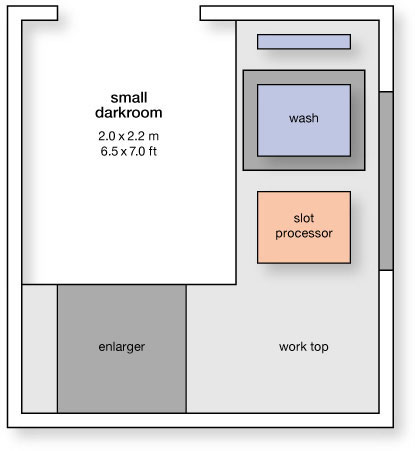
fig.2 A vertical slot processor makes it possible to reduce darkroom dimensions to a minimum, yet it can produce prints up to 16x20 inches.
Verify the effectiveness of your light proofing efforts after giving your eyes a chance to adapt to the newly created darkness for at least 20-30 minutes. This is likely to reveal some remaining light leaks, and they need to be given further attention.
Walls
There was never any benefit to the old idea that all darkroom walls should be painted black. Modern darkrooms have ceiling and walls painted in white or any other light and friendly color, except for the area around the enlarger, which should be painted flat black. A light color helps to diffuse and evenly spread general darkroom illumination and safelighting. Black walls serve no practical purpose but create an unnecessarily depressive atmosphere.
Ventilation
Inevitably, darkroom chemicals slowly release unpleasant and sometimes toxic odors. Large open trays are the worst offenders, due to their large liquid surface areas. This problem is more severe in a small space, but vertical slot processors are a big help, because they feature extremely small liquid surface areas, which minimizes unwanted odors and reduces chemical oxidation rates, while only occupying a remarkably small footprint. Nevertheless, some chemicals require the darkroom to be equipped with active ventilation, most commonly provided by a regular extractor fan in combination with an air inlet, but both fitted with a custom-made, light-trapping air-path (see fig.6). To keep things pleasant in a domestic environment, the fan must exhaust to the outdoors and not into an adjacent room. Even so, some chemical processes, such as sulfide toning, are either a threat to human health or at least sufficiently unpleasant as to leave outdoor processing as the only option.

fig.3 Given sufficient floor space, a light-trapping entrance provides easy access without interrupting the ongoing darkroom session for others. The inside walls are painted flat black, and an optional set of light curtains provides extra protection if the darkroom entry is exposed to bright daylight.

fig.4 Regular door surrounds (a) have significant light leaks (b), which are easily eliminated by adding a light-trap in combination with a floor board (c) and painting all involved surfaces with a flat black paint (d).

fig.5 Common light-proofing solutions for windows are rigid boards (right, here used outside) or black hook-and-loop fasteners in combination with opaque cloth (left, here used inside).
Heating and Air-Conditioning
The choice of room has a significant influence on how easily a comfortable temperature can be maintained. For instance, basement darkrooms have a nearly constant temperature throughout the year and require the simplest of domestic appliances to maintain a stable temperature. Darkrooms in attics, garages or sheds, suffer from temperature extremes. For example, a large exposed roof area can heat or cool a room over a 35°C range, even with mild UK seasons. Insulation is an important consideration in such case, mitigating the issue to some extent, but without air-conditioning, these darkrooms may be out of bounds during the summer months, especially in warmer climates.
If a darkroom requires additional heating, it is best to avoid electrical fan heaters, because they circulate dust. Modern oil-filled immersion heaters are thermostatically controlled, safe, darkroom friendly and are available in a number of power levels. Some models have 24-hour timers, which allow setting a precise room temperature and warm up a darkroom prior to an early morning printing spree. However, darkroom processes themselves add heat and humidity to the room, which may require a dehumidifier or an air-conditioning unit. Since darkrooms invariably produce chemical fumes, a unit that exchanges air is preferred and helps with darkroom ventilation.

fig.6 Unwanted darkroom odors are effectively removed with a regular extractor fan and a custom-made, light-trapping air-path, which is illustrated here by a cut-away.
Safelights
A single safelight, mounted in the center of the ceiling, provides effective illumination around the darkroom. Unfortunately, with such a light, no matter where you are in the room, you are inevitably working in your own shadow. Multiple low-powered safelights, strategically positioned above key work areas, solve this problem. As a rule of thumb, limit yourself to one 15W safelight for every 2 m2 of darkroom floor space, and maintain a minimum distance of 1 meter between any safelight and open paper. Some enlarger timers reduce unnecessary safelight exposure by leaving safe-lights on for focusing but conveniently turning them off during metering and printing. Detailed safelight specifications are discussed in the next chapter.
White Lights
In addition to the safelights, a darkroom also needs white lights for general room lighting and final print evaluation. For both purposes, incandescent lighting is preferred over fluorescent lighting. Incandescent bulbs are designed for frequent on/off switching. They have no lengthy ramp-up and are immediately at full power, which they maintain consistently. The bulbs do not continue to glow after they are turned off, and their color temperature is similar to typical domestic and gallery lighting, making incandescent lighting more conducive to accurate image tint evaluation.
A dedicated location for dry or wet print evaluation is an important feature of a well-designed darkroom. The area should be evenly illuminated and closely simulate final viewing conditions. Prints produced and evaluated in brightly lit darkrooms end up looking too dark in dimmer environments. A 60-100W opal tungsten bulb, a distance of 1-2 meters from the evaluation board, provides an illumination of around EV 6 at ISO 100/21° (see fig.8). This setup simulates rather dim display-lighting conditions and is ideal for dry print evaluation. However, don’t forget to consider print dry-down when evaluating wet prints.
Dry Side and Storage
The wet and dry areas of a well-designed darkroom should be separated for obvious reasons. Nevertheless, this becomes increasingly difficult as the room becomes smaller, and at some point, more imaginative solutions are required to organize the available space. A practical solution for darkroom furniture is using kitchen units with laminated worktops. This provides a clean work area and plenty of room for storage, which keeps enlarger, printing paper, negatives and other sensitive materials and equipment a safe distance from the wet side. Chemicals must be secured and kept out of reach of inquisitive children. Film and paper stock is best kept in a dedicated refrigerator.
A light-tight drawer keeps the printing paper accessible and protected during the entire darkroom session (fig.7). Use an existing drawer and cut a groove around its inside top perimeter. Install a sliding lid that fits in that groove and paint the inside of the drawer and the lid flat black. Now, attach a pair of small blocks of wood, one on the top of the lid and another one on the underside of the worktop. These blocks will close the lid when you close the drawer.
The effect of stray light, either directly from the enlarger or reflected from its surroundings, is effectively minimized by painting adjacent walls with matt black paint or hanging up black curtains. There should be sufficient headroom for the enlarger to reach its full height. Further enlargement can be achieved through lowering the baseboard or horizontal projection. During printing, a large uncluttered worktop is useful for laying out printing materials, negatives and burning or dodging tools. After print processing, this worktop can also be used as a matting and mounting area.
Wet Side and Plumbing
It is possible to design a darkroom completely without running water, which forces you to bring in buckets of water as the main water supply, create holding tanks, and carry chemically processed prints to another room for washing. This may suffice for a temporary darkroom setup, but it quickly becomes cumbersome. To work efficiently, a darkroom must have running hot and cold water, as well as waste-water drainage.
Another darkroom convenience is one or two large darkroom sinks. A small sink, with a work surface right next to it, works well for vertical slot processors and careful practitioners, but large sinks are ideal for tray processing. Having two sinks next to each other effectively separates chemical processing from print washing and provides an additional wet area to clean up recently used equipment. Professional plastic and steel sinks are manufactured in various sizes, but they can also be custom-made from wood with fiberglass lining. Substantial darkroom sinks employ a modular steel, or wooden, framework to support the sinks and provide shelf space underneath. A very useful feature is raised ridges in the sink, which are level for the trays to sit on but still allow the sink bottom to slope gently back to the drain (see fig.11).

fig.7 A light-tight drawer keeps the printing paper accessible and protected during the entire darkroom session.

fig.8 A dedicated location for print evaluation is an important darkroom feature. It should be evenly illuminated and closely simulate final viewing conditions.
Further refinements may include an automatic mixing valve that electronically controls water flow and temperature, which is an investment neither of us ever regretted. Also, the availability of multiple faucets provides the opportunity to install dedicated plumbing for an archival print washer, while still having running water for other purposes. Alternatively, one may attach a range of devices to the same faucet with snap-fits, such as those used for garden hoses.
Water quality varies between regions and should not be taken for granted. Some supplies carry sediment, which may potentially damage wet negatives or become permanently embedded in the film or print emulsion. Sediment can be avoided by installing an in-line water filter, and by using distilled water for the film chemistry and the final rinse. This also reduces the possibility of creating drying marks with hard water deposits. Please note that highly dilute developer solutions are susceptible to alkali or acid water supplies, and that it is best to bypass the water softener for more effective film and print washing. Environmentally responsible darkroom workers collect used darkroom chemicals and hand them over to their local waste management centers rather than pouring them down their drains.
Cleanliness
Fastidious cleanliness is not optional when trying to produce fine-art prints. To avoid contamination during processing, use only dedicated equipment for each processing step, and never move utensils backwards in the processing chain. For example, once a plastic bottle has been used for developer, always use it for developer. And, if a print tong has been accidently moved from the developer to the stop bath, do not move it back until it has been thoroughly cleaned. That’s why they are color-coded! At the end of your darkroom session, clean and dry all trays and utensils immediately. Liquid darkroom chemicals are easily washed off. Dried fixer, for example, is a different story.
Keeping dust under control minimizes the need for print spotting. Reduce dust levels by keeping the darkroom door closed. Surfaces made of ceramic tiles, sealed concrete or hardwood flooring and rubber mats work well, since they are not only dust free, but they are also easy to clean, and accidental spills can be mopped up quickly. Carpets, on the other hand, collect dust, are hard to keep clean and build up static charges. Storing the enlarger and easel under a dust cover and wearing only lint-free clothing are precautions that reduce the need for spotting the prints later on.

fig.9 This remarkable attic extension contains a darkroom and an office. The enlarger is set at the apex with the wet side to the left and the office to the right. The film processor is inside a large plastic sink, and beside it, a vertical slot processor juts out into the room to allow enough headroom to pull out a print. Underneath, a pullout unit stores film and paper processing chemicals.
Darkroom Safety
Besides being a comfortable recreational place, darkrooms must also be safe environments. Always keep in mind that electricity and liquids do not mix. At some point, wet hands will operate electrical devices. For this reason, all electrical outlets must have earth-leakage protection. Fuse ratings must match the equipment requirement, and all electrical outlets must be positioned away from likely splash sources and certainly not upward facing. Unoccupied outlets are safer if fitted with childproof covers. Allow no electrical wiring on the floor to prevent the danger of tripping over it in the dark.
Darkrooms are not inherently dangerous places, but the limited illumination level, the use of potentially hazardous chemicals, and the close proximity of electricity and water must be seriously considered. Eating, drinking and smoking are not compatible with safe darkroom practice. Also, consider indicating the position of switches, electrical outlets and door handles with luminous paint or stickers. Designing and building your own darkroom is a satisfying experience, but if ever you are in any doubt, play it safe and hire a certified craftsman for all electrical, plumbing and heating installations, and make sure all local building codes have been followed.
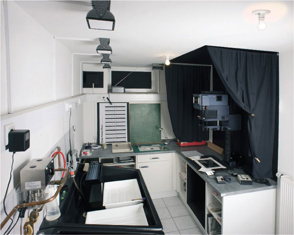
fig.10 This medium-size darkroom in Ralph’s basement offers a clear separation of wet and dry processes and ample space for tray processing. Multiple safelights are distributed throughout the room, and stray light from the enlarger is minimized by black curtains.

fig.11 Chris’s garage darkroom has everything he needs to create prints up to 16x20 inches. It is home to a 4x5 enlarger, a print washer and a vertical slot processor. The garage is effectively insulated with polystyrene blocks to keep the temperature at a pleasant 20°C.
How Safe Is Your Safelight?
Two simple, reliable tests with surprising results
We want our photographic paper to be sensitive to light, but we do not like to be in complete darkness when we work with it. The photo industry has a solution for this contradiction.
Photographic paper is only sensitive to a certain range of the visible spectrum. In addition, safelight filters transmit only light from a different range of the visible spectrum. This way, our eyes and the paper are sensitive to the light projected by the enlarger, but only our eyes and not the paper are sensitive to the light illuminating the darkroom.
Fig.1 shows how sensitive variable-contrast (VC) papers are to blue and green light, which require a safelight output limited to wavelengths above 560 nm, in order to protect the paper from unwanted exposure. Kodak’s ‘light red’ (1A) and ‘light amber’ (OC), or Ilford’s 902 and 904 safelight filters fulfill this requirement. Filter 1A provides more protection, because it only transmits wavelengths above 600 nm, but the eye is not particularly sensitive to this light, and consequently, this filter makes for a rather dim darkroom environment. The OC filter, on the other hand, transmits light in wavelengths very close to the human peak sensitivity, providing a much brighter workplace and softer illumination. Both filters are sold as being ‘safe’, because they do not emit any light to which typical papers have any significant sensitivity.
Unfortunately, this is not entirely true for several reasons. First, the papers are not totally insensitive, but have a very low sensitivity outside the intended spectrum. Second, the safe-light filters transmit minute levels of light outside their intended spectrum, and this effect increases with their age. Third, the safelight housing, depending on design and quality, may have some minor, unintended light leaks.

This requires that we rephrase the statement about safelights. Safelights protect photographic paper only for a limited amount of time, after which non-image forming exposure becomes visible. Consequently, we need to know how long the paper is protected, and how to test the safelight condition reliably.
Paper Characteristics
You can see in fig.2 how photographic paper responds to the light it was designed for. The paper characteristic curve represents density levels achieved by any given amount of exposure.
Initially, illustrated through the shallow ramp up at the toe of the curve, a small amount of exposure is required just to get the paper ‘started’. Minute amounts of light leave the paper unaffected until a moderate amount achieves the ‘first usable density’. The human eye is most discriminating to the small differences in density in these highlight areas.
The paper, on the other hand, is most sensitive in the midsection of the curve, where even small exposure changes result in significantly different densities. In the shoulder of the curve, a certain density saturation has taken place, and additional exposure add relatively small density increases until a maximum black has been reached. The human eye is not particularly sensitive in these shadow areas, and is unable to see density differences after a certain point, which is referred to as the ‘last usable density’.
Image Exposure
The paper characteristic curve in fig.2 also illustrates that small amounts of exposure, similar to typical safelight illuminations, do not harm unexposed paper, because this limited exposure cannot overcome the initial inertia of sensitivity. A certain amount of light is first required to get beyond the horizontal portion of the toe. In a typical darkroom session, this hurdle is taken when an exposure is made to get the brightest tonal values of the image to the point of the ‘first usable density’. This exposure sensitizes the paper to any further illumination. From this point on, even small amounts of exposure will increase density in all tonal values, but most visibly in the highlights. Safelight illumination, both before and after this image forming exposure, can only be tolerated for a certain length of time, after which a density increase visible to the human eye results. We will try to duplicate these conditions to design a practical and representative safelight test.
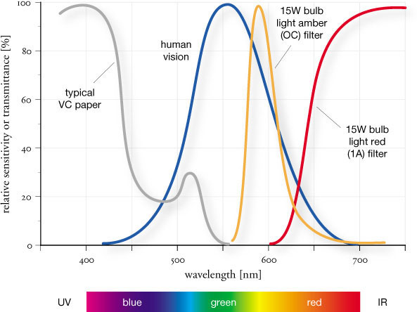
fig.1 Incandescent illumination in combination with light amber (OC) or light red (1A) filtration protects the paper against fogging for several minutes, because it does not emit any significant radiation to which the paper is sensitive. However, amber filters provide more visible radiation than red filters, creating a much brighter environment in the darkroom.

fig.2 The paper characteristic curve shows how paper densities increase with exposure. Initially, however, minute amounts of light leave the paper unaffected.
Safelights protect photographic paper only for a limited amount of time, after which non-image forming exposure becomes visible.
Typical variable-contrast papers are appropriately protected with a light-amber (OC) safelight filter, but some papers need the stronger protection of a light-red (1A) filter. Fast orthochromatically sensitized papers need the strongest protection and require a dark-red (2) filter.
Simulating Image Exposure
The image exposure through the negative is best simulated with the ‘optimum safelight test density’. This is a good compromise between the ‘first usable density’ (Zone VIII), where the eye is most sensitive to density changes, and the ‘linear midsection’ (Zone V), where the paper is most responsive to exposure increases.
In total darkness and without film in the negative carrier, produce a test strip on ‘normal’ graded paper, to find the enlarger exposure required to produce the ‘optimum safelight test density’. This is a light gray tonal value between Zone VI and Zone VII, or about 0.3 reflection density. A high degree of accuracy is not required at this point. Use a step tablet, a zone ruler, or print it just a little darker than you typically print your textured highlights.
A Precise Test
You will need a single sheet of 8x10-inch paper and two thick pieces of cardboard. One piece, the mask, requires a 4x8-inch cutout, and the other piece is needed to cover the test strips. Trim one corner of the mask, because this will aid in the orientation of the paper. Make sure that all processing chemicals are prepared. A ‘normal’ filter is placed into the light path and the lens is set to an aperture that, in combination with the proper exposure time, will produce the ‘optimum safelight test density’. Place an empty tray on top of the development tray, which will be required later as a physical support for the paper.
The following steps can be executed in any order, since the exposures are accumulative. Customize all times to simulate your own work habits.
1. On the Baseboard
In the dark, center the paper on the baseboard and cover it with the mask. Turn the safelight on. Immediately cover the first horizontal step, about 1 inch, and continue to cover more steps resulting in a practical pre-exposure sequence that reflects your own work habits. I usually simulate pre-exposure paper handling from 0-16 minutes in intervals as shown in the examples. As an optional step, you could turn the enlarger ‘on’ for the first 2 or 3 minutes of the pre-exposure, while shading the paper with one of your dodging or burning tools. This tests for any light leaks from the enlarger and/or reflections from the surrounding walls. Turn the safelight off.

fig.3 This safelight allows for 6-minute paper handling on the baseboard but only 2 minutes in the development tray, a performance hardly worthy of being referred to as ‘safe’.

fig.4 This safelight allows for 11-minute paper handling on the baseboard and 8 minutes or more in the development tray. This is fully adequate for most printing sessions.
2. Exposing the Print
While still in the dark, turn the enlarger on to expose the paper for the ‘optimum safelight test density’. This simulates the image exposure and was pretested earlier. Leave the safelight off.
3. In the Developing Tray
Again in the dark, place the paper with the mask on top of the development tray. Turn the safelight on. Immediately cover the first vertical step, about 1 inch, and continue to cover step by step creating a practical post exposure sequence, reflecting your own work habits. I usually simulate post exposure paper handling, including the development process, from 0-8 minutes in intervals as shown in the examples. Some printers ignore this step, because they believe that paper loses its sensitivity to light as soon as it becomes wet. I have found no evidence for this claim. Finish the test by processing the paper normally in the dark.
Test Evaluation
Three possible results are shown in the test print examples. Keep in mind that the top left patch, which we will refer to by its coordinates 0-0, has not been exposed to any safelight, but was sensitized, simulating print exposure, in step 2.
The first example, see fig.3, was exposed to two different safelights, one close to the enlarger and the other above the development tray. The test shows a very poor safelight performance. The last patch matching the gray value of the top left corner is patch 2-6. This means this paper should not be exposed to the safelight conditions around the baseboard for any longer than 6 minutes. The safelight conditions at the development tray allow for an additional exposure of no more than 2 minutes. The baseboard time could be adequate, if no special paper handling were required, but the time in the development tray is too short for even the processing of resin-coated papers. The owner of this darkroom should check all safelights, but the light near the development tray needs to be replaced or checked for light leaks.
The second example, see fig.4, was exposed to the same safelights after bulbs and filters were replaced, and a small light leak in one of the housings was taped over. The test shows a very good safelight performance. The last patch matching the gray value of the top left corner is patch 8-11. This means that the paper can be exposed to the safelight conditions around the baseboard for about 11 minutes. The safelight conditions around the development tray allow for an additional exposure of at least 8 minutes. The baseboard time is long enough for most paper handling, and the time in the development tray is adequate for the processing of fiber-base papers. The owner of this darkroom can trust the safelights unless special processes, like lith printing, requiring long times in the development tray are used. In that case, the test times have to be modified to reflect the special requirements.
The third example, fig.5, was exposed with the same safelights as in the previous example, with one addition. The enlarger was ‘on’ during the first 3 minutes of the pre-exposure, while the paper was shaded with a burning card. The test shows a very good safelight performance, but enlarger light leaks and reflections have reduced this to less than 2 minutes.

fig.5 Here the enlarger was ‘on’ during the first 3 minutes of the pre-exposure, while the paper was shaded with a burning card. The safelights protect as in fig.4, but enlarger light leaks and reflections fog the paper in less than 2 minutes.
The last patch matching the gray value of the top left corner is patch 8-0 and no further change can be seen until patch 8-11. This means that the paper can only be exposed to the safelight conditions around the baseboard for less than 2 minutes. The safelight conditions around the development tray allow for an additional exposure of at least 8 minutes. The time in the development tray is adequate, but the baseboard time is too short for real world paper handling. The owner of this darkroom must make several changes to the darkroom. Suggestions would include the following steps. The walls around the enlarger should be painted flat black. The enlarger itself should be checked for light leaks and reflections. Confirm that cards, used for dodging and burning, do not transmit any light to the print. The printer should also wear dark clothing to reduce reflections.
This valuable test can be performed in about 30 minutes, and I repeat it every 3 to 6 months, just to be sure. It is a great assurance to know that the safelights are not affecting print highlights and image quality during normal processing times.
The Coin Test
The previous test clearly identifies any source of light contamination and quickly points to the area that requires improvement. The coin test is not quite that sophisticated and does not discriminate between different sources of light contamination, but properly executed, it is a reliable check and is easily done.
1. In the dark, pre-expose a sheet of paper, so it will produce a light-gray density, once it is processed.
2. Still in the dark, put the paper on the work surface, right under your safelight, and randomly distribute six coins on the paper, as seen in fig.6.
3. Now, turn the safelight(s) on, and after 1 minute, remove the first coin.
4. Remove the other coins after a total of 2, 4, 8 and 16 minutes, but do not remove the last coin.
5. After 32 minutes, turn off all safelights, remove the last coin, and process the paper normally.
Depending on how ‘safe’ your safelight illumination is, the coins will have left more or less ghostly evidence about their previous positions on the paper. After this quick test, you will have a pretty good idea of how long you can work under the safelights, without adding unwanted fog to your print’s highlights.
The test example in fig.6a illustrates the effect of a poor safelight protection. With the exception of the 1-minute coin, all coins have left their telltale signs. This indicates that the safelight illumination is, unfortunately, strong enough to affect the print’s highlights in less than two minutes.
The test example in fig.6b, on the other hand, indicates a fully adequate safelight protection. The only still-visible remnant is the shape of the coin that covered the paper for 32 minutes. This safelight can be trusted to protect delicate print highlights for at least 16 minutes and maybe longer.

fig.6 The coin test is not as sophisticated as a precise safelight test, but it is a reliable check and is easily executed.
Enlarger Light Sources
The difference between condenser and diffusion enlargers
The enlarger is the fundamental instrument of every darkroom worker, and considerable thought should be given to its selection. After considering the most obvious enlarger specifications, including supportable negative formats and the sturdiness of design, an informed choice of light source must be made. Unfortunately, the enormous amount of conflicting information available on this topic does not make this an easy task.

© 2008 by Marco Morini, all rights reserved
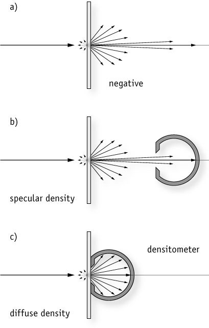
fig.1 When light falls onto a negative, some of it is reflected and absorbed, while the remainder is scattered and passed through the negative (a). Depending on how density is measured, different numerical values are obtained. Specular density is given when only the near perpendicular component of the transmitted light is measured (b). Diffuse density is obtained if the entire transmitted light is considered (c).
The majority of enlarger light sources can be separated into two categories: condenser and diffusion. Selecting one light source over the other is often influenced by the advice of more experienced darkroom workers’ biases and subjective advertisement claims. This chapter attempts to objectively compare both enlarger light sources.
Density Measurements
When light falls onto a negative, some of it is reflected, some is absorbed, and the remainder is scattered and passed through the negative (fig.1a). The exact pattern of light scatter depends on the light source and the material properties of negative emulsion and substrate. Different numerical values for negative density are obtained, depending on how the transmitted light is measured. Specular density is given when only the near perpendicular component of the transmitted light is measured (fig.1b). Diffuse density is obtained if the entire transmitted light is considered (fig.1c).

fig.2 The Callier coefficient or Q-factor is the ratio of specular to diffuse negative density. It varies with negative gamma and initially differs with the amount of diffuse negative density before reaching a constant value.
In practice, enlarging a negative and measuring its projected transmission density (fig.1b) returns a specular density reading, and measuring the negative transmission density with a densitometer in contact (fig.1c) returns a diffuse density reading. One way to compare the effect of specular versus diffuse density is to note the reflection density differences between an enlarged and a contact-printed step tablet.
Callier Effect
At the beginning of the 20th century, André Callier (1877-1938), a young Belgian physicist, was the first to thoroughly investigate light scattering in silver-based photographic negatives and to analyze the relationship between specular and diffuse density. He demonstrated that the silver particles, which make up the image, are the main reason for the light scatter, and that the light loss to this scatter is responsible for the fact that specular density values are always higher than their diffuse counterparts.
Callier Coefficient
The Callier coefficient or Q-factor is the ratio of specular density (Ds) to diffuse density (Dd).
![]()
Callier believed that Q is a constant at all values of diffuse negative transmission density for a given film/developer combination, and that it is possible to apply a simple density correction to any densitometer reading and compensate for specularity.
It was eventually discovered by other researchers that the Callier coefficient does indeed increase with negative grain size, but that Q is not a constant. Even if the same film/developer combination is used, Q varies with negative gamma and initially differs with the amount of diffuse negative density, before reaching a constant value. Fig.2 shows typical values for Q when projecting fine-grain negative film with a common condenser enlarger. Obviously, a simple density correction for specularity cannot be made.
It is important to repeat that the Callier effect results from the scattering of light by the silver grains in a conventional silver-gelatin negative. It does not occur with the non-scattering dye images of chromogenic films or ordinary color negatives.
Condenser versus Diffusion Enlarger
The difference between condenser and diffuser enlargers lies in the way they distribute the light over the negative to provide uniform illumination. In condenser enlargers, a set of two plano-convex lenses, with the convex sides facing each other, is used to collimate the light and project it perpendicularly onto the negative (fig.3a&b), whereas in the simplest of diffusion enlargers, the light illuminates a translucent diffusion screen close to the negative (fig.3c). This fundamental design difference between condenser and diffusion enlargers has a significant impact on the overall contrast of the projected image. Callier’s investigations revealed that collimated light sources lose significantly more light to scatter than diffused light sources. Since collimated light sources project the light perpendicularly onto the negative, most of the light scattered by the image particles is reflected away from the lens. A highly diffused light source, on the other hand, generates illumination coming from all angles, and as a result, much of the scattered light is reflected towards the lens. This explains why condenser enlargers have considerably higher Callier coefficients than diffusion enlargers. Furthermore, assuming a fairly constant Q-factor across all diffuse negative densities, negative highlights lose more light than negative shadows in absolute value, because they are richer in silver deposits and scatter more light. This is why a condenser enlarger produces a higher-contrast print from the same silver-gelatin negative than a diffusion enlarger.
In practice, the contrast difference between condenser and diffusion enlargers amounts to about one paper grade. In other words, to produce an equivalent print, the average silver-gelatin negative requires a paper that is about one contrast grade softer when using a condenser enlarger than when using a diffusion enlarger. However, this contrast difference is only an issue when trying to produce equivalent prints from the same negative, using different enlargers. Photographers who predominantly use just one type of enlarger should develop their negatives to support their enlarger’s contrast behavior. In simple terms, a high-contrast enlarger needs a low-contrast negative, and a low-contrast enlarger needs a high-contrast negative. The optimal negative-contrast value depends on the enlarger’s Callier coefficient for a particular film/developer combination.

fig.3 Actual negative illumination differs with enlarger design. Enlargers using a point light source and a set of double condensers to collimate the light (a) produce nearly totally collimated illumination. A condenser enlarger (b) with its relatively large light source supplies a semi-diffused light. By replacing the condensers with a diffusion screen, a diffusion enlarger (c) ensures nearly totally diffused negative illumination.

fig.4 A condenser enlarger creates higher projection densities and more contrast than a diffused light source.

fig.5 Condenser and diffusion enlargers produce prints of identical tonality with negatives, which were developed to an average gradient, appropriate for each enlarger (a1 and b1). A negative that prints well with a condenser at grade 2 prints too soft with a diffuser at the same grade (a2), and a negative that produces a perfect print with a diffuser prints too hard with a condenser (b2). However, adjusting the paper contrast compensates for a less than perfect negative contrast and produces almost indistinguishable prints with either enlarger (a3 and b3).
(all images optimized for highlight density)
All condenser enlargers, except those with a true point light source, are partially diffusing. Point-light-source enlargers (fig.3a) are usually limited to scientific applications, but they serve as an example of totally specular illumination. A more typical arrangement for condenser enlargers is to use a large opal bulb inside of a reflector housing (fig.3b). This design adds diffused light and places a typical condenser enlarger about halfway between specular and diffuse illumination with an average Q-factor of approximately 1.2 (fig.4). By reducing the film development time, and thereby lowering the negative’s contrast, any contrast increase due to the Callier coefficient can be fully compensated. The target value for the average gradient of a specific condenser enlarger (γ s) is given by:
![]()
where ‘γ d’ is the optimized average gradient for totally diffused illumination (typically 0.57), and ‘Q’ is the enlarger’s Callier coefficient for a particular film/developer combination. Customizing negative contrast in this way ensures equivalent prints with condenser and diffusion enlargers on the same grade of paper.
Pictorial Comparison
To compare the tonal differences between condenser and diffusion enlargers, a low and high-contrast negative were prepared, and both were printed with a Durst L1200 condenser and diffusion head. The negatives were developed to an average gradient of 0.47 and 0.57, optimized for typical condenser and diffusion enlargers, respectively. In each case, the print exposure was adjusted to keep a constant highlight density in the white walls of the exposed-beam buildings (fig.5).
Condenser and diffusion heads produced almost identical prints from the negatives, which were optimized for their light sources (a1 and b1). However, swapping the negatives and printing them with the other ‘wrong’ light source produced prints that were either too soft or too hard (a2 and b2). Nevertheless, adjusting the paper contrast compensated for the wrong negative contrast and produced almost indistinguishable prints with either enlarger (a3 and b3). Given the results from this test, there seems to be no justification to pick one type of enlarger over another for tonality reasons, as long as negative or paper contrast is adjusted to fit the light source (fig.6).
Sensitometry Verification
To confirm the conclusion reached on the basis of the pictorial comparison, the test was repeated with two step tablets. This verified the assumptions made from the pictorial examples in fig.5, because the same negative printed with a condenser and a diffusion enlarger produced two prints of very different tonality. However, printing contrast-adjusted negatives on each enlarger produced an almost identical print tonality.
Dust and Scratches
Condenser enlargers are claimed to be sharper and to show more detail than diffusion enlargers, but they have the disadvantage of highlighting dust and scratches, and requiring more print spotting. All these characteristics are based on the scatter of collimated light, which is caused by silver particles, dust and scratches alike. When compared at a 10x negative magnification, the difference between condenser and diffusion enlarger is clearly visible (fig.7). The effect increases with negative magnification, but at normal viewing distance, this will not make for a more detailed print, nor will it save you from print spotting.
There are obvious differences between condenser and diffusion enlargers when it comes to their design and handling. Condensers make more efficient use of the light source and offer a minute increase in acutance, which makes them ideal for 35mm enlargements. Diffusion enlargers reduce the need for print spotting and typically offer stepless contrast changes. But given the right negative, both are perfectly capable of producing a smooth, full-scale print.

fig.6 Printing two step tablets verified the conclusions made from the pictorial examples in fig.5, because the same negative printed with a condenser and a diffusion enlarger produced two prints of different tonality. However, printing contrast-adjusted negatives on each enlarger produced two prints with almost identical print tonality.

fig.7 Condenser enlargers are claimed to be sharper and to show more detail than diffusion enlargers, but they have the disadvantage of highlighting dust and scratches and require more print spotting. When compared at a 10x negative magnification, the difference is clearly detectable, but at normal viewing distance, this will not make for a more detailed print, nor will it save you from print spotting.
Sharpness in the Darkroom
Maximum resolution from corner to corner
The essentials to make the sharpest prints in a darkroom setup are well known and documented in many good photographic texts. It is surprising, therefore, that such simple advice is all too often ignored in the many darkrooms we have visited. Our recommended practices are compiled and explained here, including measured discussion on some of the myths of focusing.
Enlarger Stability
It goes without saying that the enlarger must not wobble during the exposure. Objects can only wobble if they are unnecessarily provoked or not sufficiently constrained. If you have a permanent darkroom setup, our advice is to remove the column from the baseboard and rigidly mount it to the wall, as shown in fig.1.
This isolates the enlarger from floor and table vibrations, and enables vertical column adjustment to level the enlarger head. Wall-mounting brackets are available from some enlarger manufacturers and independent retailers. Alternatively, mount the baseboard column bracket to a rigid wall-mounted shelf, and fix the top of the column to the wall with a homemade bracket. Another benefit from using a wall-mounted enlarger is the ability to lift the column upwards and outwards, so a large printing easel fits under the column for big enlargements. A wall-mounted column must be adjusted using a small spirit level, so that the negative plane is horizontal, both side to side and front to back, as shown in fig.2. Having set up the enlarger, check the rigidity of the setup by observing the stability of the projected image with a grain magnifier.

fig.1 This professional Durst L1200 enlarger is wall-mounted through an aluminum bracket, which supports the enlarger’s weight and isolates the column from vibration.
fig.2 A spirit level is used to check the vertical alignment of an LPL enlarger column.
During the exposure, minimize the excitation of the enlarger and baseboard, especially if you are unable to wall-mount the column. If you touch the enlarger, wait for the vibrations to settle down before making an exposure, and then, be careful not to move about or touch the base unit or the table it stands on. Also, if you enjoy listening to music while working in the darkroom, make sure that the speaker boxes are not on the same table as the baseboard. Even heavy outside traffic and nearby railway lines have been known to cause problems. If you have a darkroom timer with a foot switch, use it like a cable release.
Film Flatness
Film does not lie flat naturally. Heat, storage conditions and humidity all affect its natural curl. In the same way that a camera requires the film to be flat, so do enlargers. Glassless negative carriers do not keep the film flat. Fig.3 shows the reflection of a window frame from the film surface, which indicates how difficult it is to keep 35mm film flat in a glassless negative carrier. The problem increases with larger negatives on medium and large-format film.
We cannot rely on the depth of focus to compensate for film unevenness and secure perfect sharpness, because the room for permissible error is just too small (see fig.12). To make matters worse, as the negative warms up in the light path, it pops just as a transparency does in a slide projector. In order to ensure maximum sharpness, the film must be held absolutely flat during projection. We recommend printing the film with the emulsion side down in a negative carrier, which sandwiches the film between two sheets of glass. The extra effort of keeping the four additional glass surfaces dust-free, to avoid unreasonable print spotting, is well worth the results. Nevertheless, to keep unsightly color fringes from forming concentric rings of irregular shape between film and glass (Newton’s rings), use a specially etched anti-Newton glass on top of the film, towards the shiny film base. Usually, you can use clear glass on the other, matt emulsion side of the film. However, some films, such as Ilford XP2 and the now discontinued Agfa APX25, have a very smooth emulsion side. With these films, Newton’s rings can still occur between the clear glass and emulsion side of the film. If you use this type of film, remove the glass from the bottom altogether, and keep only the anti-Newton glass on top of the film.
Enlarger Alignment
Accurate enlarger alignment is one of the less obvious requirements for sharpness in the darkroom. A misaligned enlarger does not have the baseboard, film and lens planes perfectly parallel. This is evident in the projected image as unequal grain sharpness from one corner to the next. Precise enlarger alignment can be achieved with a simple spirit level, and this method will satisfy all but the most discerning users. However, some enlarger designs prevent convenient spirit level access to film or lens plane, requiring more sophisticated alignment technology.
Using a Spirit Level for Alignment
With the help of a spirit level, the paper, lens and negative planes are adjusted until they are horizontal and as parallel as possible.
1) The easel surface is made horizontal, both back-to-front and side-to-side, either by adjusting the feet or the entire table, possibly using spacers.
2) The wall-mounted column is adjusted vertically, side-to-side and front-to-back, so the negative stage is horizontal front-to-back, as seen in fig.2. In some cases, the customary holes for wall-mounting screws may need to be filed into slots, to enable adjustment of the top and bottom column brackets.
3) Assuming the enlarger head has a tilt feature, adjust it so the negative stage is horizontal, side-to-side. If the head is fixed, then the column will need further adjustment to counteract the error.
4) Lastly, the spirit level is held against the front face of the enlarging lens and the lens stage is leveled, either by the available adjustments or by inserting a spacer into the mechanism.
fig.3 This close-up of a glassless 35mm negative carrier clearly indicates an uneven film surface, seen in the reflection of a nearby window frame.

fig.4 A small laser module can be bought from any electronic shop for the price of a few films. To turn it into a self-made laser alignment tool, a housing with a leveling feature has to be made, and the leads have to be connected to a power supply. A detailed technical drawing for a potential implementation is found under ‘Tables and Templates’ in the appendix.
Constructing a Laser Alignment Tool
A simple laser module can be bought for the cost of a few rolls of film from any good electronic shop (fig.4). With a little ingenuity, it can be fashioned into a useful alignment tool by gluing it into a machined metal cylinder, which in this case was manufactured according to the sketch in fig.5a. Three tapped holes were added to the base of the cylinder to accept small adjustment screws, which assure the laser beam is perfectly vertical when the housing is placed on a horizontal surface. The screws level the laser alignment tool, using the following procedure:
Place the laser alignment tool on the baseboard, and use two heavy objects to form a corner, so that when the alignment tool is rotated, while being pushed into the corner, the center of the laser remains in a fixed position. As the tool is turned, note the position of the laser beam on the ceiling, using some masking tape and a pen. Initially, the laser will trace out a small circle. Turn one or two of the adjustment screws, until the beam aims at the center of this circle. When the adjustment is accurate, the red light spot appears stationary during rotation of the tool. Having calibrated the laser alignment tool, the screw positions can be fixed with a little varnish.
Using a Laser Alignment Tool
If you prefer a professionally made enlarger alignment unit to the self-made variety, we recommend that you check into the ‘zig-align’ system or the ‘Parallel’ alignment gage made by Versalab. They can be purchased for the price of a good enlarging lens.
It is sensible to start the laser alignment process with a previously leveled easel and a vertically aligned column. Turn the laser on, making sure to never point it at someone’s eyes, and adjust negative and lens stage in sequence as follows, while judging the results according to the instructions in fig.6.
1) Raise the enlarger head to the top of the column and lock it as you would during normal operation. Remove the enlarger lens, and place the laser alignment tool directly beneath the opening just created. Adjust the negative stage until the laser beam’s reflection from the negative-carrier glass aims back at the laser exit hole as closely as possible.
2) Return the enlarger lens, and with a filter fitted to its attachment ring or a piece of glass just held against its front surface, adjust the lens stage until the laser beam reflects back on itself, which indicates that it is parallel to the baseboard.

fig5a&b With some ingenuity and help from a local machine shop, a self-made laser alignment tool is brought from concept to reality. Three adjustable screws level the unit and align the laser module until it projects a perfectly vertical laser beam.
fig5c The finished laser alignment tool is leveled on the baseboard and placed directly under the enlarger. The laser is then made to reflect off the negative carrier and the lens plane. The location of the reflected laser beam is a measure of misalignment.
Centering the Lens
Whichever alignment method you use, it is essential to check that the lens axis is centered in the negative area. To do this, take a fogged negative leader, the same format as your negative carrier, and scratch in two diagonal lines to locate the middle. Center and project this negative on to the easel. Mark the intersection on the easel, and check that this point does not travel across the easel as the head is moved up and down the column. Use the horizontal adjustment mechanism on the lens stage to centralize the lens. After any adjustment, confirm the lens alignment with a spirit level or the laser alignment tool.
Enlarging Lens
It is pointless to use the best camera lens if the print is let down by a poorly performing, cheap enlarging lens. There are many manufacturers of quality optics, Nikon, Schneider and Rodenstock to name but a few, and excellent used Leica and Minolta lenses are available. As with many products, the purchase price is an indicator, but not a guarantee, of the quality of a particular enlarging lens. However, you can minimize the risk by selecting a name-brand, high-quality, six-element, multi-coated lens. This is most likely to ensure high performance in the 4-12x range of enlargements. Nevertheless, several authors have reported that manufacturing tolerances within a brand can vary more than from brand to brand. It is a big advantage, therefore, to buy your lens from an understanding dealer, who lets you check its performance against others.
The optical performance of any lens changes with aperture. Enlarging lenses are no different. An optimum aperture is the best compromise between overall resolution, even illumination and exposure time. For many lenses, the optimum aperture is between f/5.6 and f/11. Keen observation, and some trial and error, will determine your ideal setting for each lens. Having found your ideal setting, try to use this aperture for all your printing, rather than using a constant printing time. After aligning the enlarger, your prints should be grain sharp, in the middle and equally at each corner. At the same time, a print made without a negative in the carrier and printed mid-gray on high-contrast paper should confirm even illumination.
If you use small-format negatives and enlarging lenses in a large-format enlarger, it is critically important to place the negative centrally in the negative carrier. The enlarging lens is designed for a certain maximum coverage and the illumination and sharpness degrade quickly outside these boundaries. In our enlargers, we use a film format template, cut from thin black plastic, which we place on the negative carrier’s top glass. It was made such that the outer dimensions snugly fit inside the glass frame’s inner edges. Once the outer dimensions of the template are trimmed, slightly oversized negative dimensions are centralized and cut out with a sharp knife.

fig.6 There is an easy way to tell if the enlarger is out of alignment, or if the laser beam is simply not perpendicular to the baseboard.
(text & illustration by Dale H. Marsh)
To judge the enlarger alignment, rotate the laser and watch the reflected beam. The examples above illustrate how you can tell if the enlarger is out of alignment or if the laser beam is just not perpendicular to the baseboard.
a) The reflected beam stays centered on the target. This indicates that the laser is perpendicular, and the reflecting surface is parallel to the baseboard.
b) The reflected beam is not on center, but it does not move as the laser is rotated. This indicates that the laser is perpendicular, but the reflecting surface is not parallel to the baseboard.
c) The reflected beam is not on center, but it creates a concentric circle around the target as the unit is rotated. This indicates that the laser is not perpendicular, but the reflecting surface is parallel to the baseboard.
d) The reflected beam is not on center and it follows a circular path not centered on the target. This indicates that the laser is not perpendicular, and the reflecting surface is not parallel to the baseboard. If the laser is adjusted closer to perpendicular, the circular path will get smaller until it matches condition ‘b’. If the reflecting surface is aligned to be more parallel to the baseboard, the path of the beam will become concentric with the laser orifice and eventually approaches condition ‘c’.
Good enlarger alignment is indicated by condition ‘a’ and ‘c’.

fig.7 The purchasing price of a particular enlarging lens is an indicator, but not a guarantee, of its quality. However, you can minimize the risk by selecting a name-brand, high-quality, six-element, multi-coated lens.
Paper Flatness
Fiber-base papers, and, to some extent, resin-coated papers, suffer from curl and unevenness. We have observed the curl of a piece of paper changing, when placed unrestricted on a flat surface and left to relax for a minute, as it adjusts to the humidity and temperature of its new surroundings. These movements can cause a loss of sharpness, especially towards the borders of the print, as the horizontal creep during the exposure blurs the image. However, a two or four-blade easel holds down the paper satisfactorily. To make borderless prints, simple side restraint easels suffice. If you do not use an easel, attach double-sided, low-tack adhesive tape directly to the baseboard. The tape is applied to the baseboard, and the print is pressed slightly against the tacky surface. This tape has a similar adhesive quality to the one used on 3M ‘Post-it’ notes, and, although tacky, it does not damage the print when lifted off the baseboard.
However, as long as the paper lies still, there is no need to be overly concerned about paper flatness. Depth of field covers a significant distance at the baseboard, especially with small film formats. An 8x10-inch enlargement, projected at a working aperture of f/8, from a full 35mm, 6x6 and 4x5 negative will have a depth of field of 28, 17 and 9.3 mm, respectively (see fig.12). This should disprove the myth that a single piece of photographic paper, with a thickness of just 10 mil (0.25 mm) and placed under the focus finder, will improve accurate focusing and print sharpness.
Accurate Focusing
Our prints have often been complimented on their excellent sharpness, and yet, our darkroom procedures are common and simple. We just focus the image at full aperture using white light, and then, stop down to the working aperture before printing. Since our results are of high quality, there was really no need to explore other alternatives. Nevertheless, while researching for this book, we uncovered a volume of opinion on numerous effects claiming to cause focusing errors, with considerable disagreement between authors. Out of interest, we have evaluated the significance of some of these effects, including ultraviolet paper sensitivity, focusing with filtered light and focusing at the working aperture.
Ultraviolet Paper Sensitivity
Ultraviolet radiation has a wavelength below 380 nm, and although enlarging lenses transmit this radiation, they are rarely corrected for the chromatic aberration below 400 nm. The data sheets from Agfa, Ilford and Kodak indicate that the spectral sensitivity of their B&W papers extends well into the ultraviolet range. Consequently, ultraviolet radiation reduces print sharpness, since the paper is sensitive to it, and the lens is not corrected for it. An ultraviolet filter (1A) has a transmittance of only 1% below 380 nm. This filter, placed below the enlarging lens, yields a sharper print but reduces the effective print exposure, if ultraviolet radiation is present in significant quantities.

fig.8 Although this picture of Chris’s daughter, Katie, is taken at full aperture with the Fuji 680 and, consequently, has a shallow depth of field, it requires corner-to-corner sharpness to ensure crisp grain over the entire print.
In practice, the insertion of an ultraviolet filter into the, otherwise unfiltered, light path of a tungsten-halogen enlarger made no detectable difference to an Agfa Multicontrast RC print, neither in print density nor in sharpness. The conclusion that the tungsten bulb emits no significant quantities of ultraviolet radiation was confirmed by the bulb manufacturer’s data sheet. A cold cathode head, whose light source uses fluorescent materials, is blue and ultraviolet rich, and therefore poses a greater potential problem. The use of an ultraviolet filter, in this case, may greatly reduce the effective exposure to UV radiation. Unfortunately, each lens, paper and enlarging light system may have its own unique focus error, ranging from minuscule to significant. Comparing two prints made with and without the use of a UV filter will identify whether you need to take corrective actions.
Focusing with Filtered Light
Patrick Gainer wrote an article titled ‘Hazards of the Grain Focuser’ for Photo Techniques Jan/Feb 1997, which explained the chromatic aberrations of the enlarger, an aerial grain focuser and the human eye. His thorough investigation used a simple series of optical experiments to clearly show the inability of the human eye, enlarger lens and the grain focuser to focus at several wavelengths simultaneously.
We repeated these experiments and arrived at similar conclusions. The expectation that optimum focusing occurs only if we focus with contrast filters in place was disproved. We found that focusing with different contrast filtration made little difference to print sharpness, and prints from 10x enlarged negatives could only be distinguished with an 8x loupe. In fact, the ability of any individual to focus consistently is more of an issue than the choice of filtration.
Some grain focusers (fig.9) provide a blue filter to focus only on the wavelength of light most sensitive to the paper. Unfortunately, the human eye is not very sensitive to blue light and the resulting image is dim and difficult to see. In our tests, this method suffered themaximum human focus variability. Patrick Gainer’s simple recommendation is to focus without contrast filters in place, and we agree that print focusing is best done with the unfiltered white light of the enlarger. This does not constitute any additional effort, because enlarger light metering must be done without contrast filtration anyway. Nevertheless, critical print sharpness is more likely to be affected by vibration, film flatness and enlarging lens quality than filtration.
Focusing at the Working Aperture
Another popular ‘tip’ is to focus at the working aperture of the enlarger lens. As the lens is stopped down, the optical aberrations of the lens, and therefore, its sharpness, improves down to the aperture at which the lens performance is diffraction limited. The assumption is that the best focus is obtained with the sharpest projected image. In addition, a low quality lens may suffer from focus-shift, where the focal length of the lens slightly changes with aperture.
A practical test, using any of our high-quality, six-element lenses, showed that there was no repeatable difference between focusing at full aperture or at the working aperture of f/8. However, as with the dark blue filter, it was difficult to focus the dim image consistently, and we concluded that it was more likely that this would cause the observer to introduce a focus variability. In addition, any minor focusing errors, still visible at full aperture, are easily lost in the depth of field at smaller working apertures.

fig.9 Focusing aids compare the aerial image reflected from a mirror with a built-in cross hair. The cross hair is in a fixed position so the length of the light path from negative to cross hair is the same as that from negative to easel. The cross hair is brought into sharp focus by adjusting the loupe, and then, the image is brought into sharp focus by adjusting the enlarger.

fig.10 As there is a zone of reasonable focus surrounding the paper plane, known as the depth of field, there is an equivalent zone of reasonable focus surrounding the negative plane, called the depth of focus.

fig.11 Taking advantage of the depth of field, minor perspective distortions can be corrected through a baseboard lift without losing reasonable sharpness.
Mural Prints
While many of the error mechanisms mentioned above cause little difference to effective print sharpness for small and medium enlargements, mural prints must be considered a special case. Focus and sharpness issues add up, and therefore, critical big enlargements require special care. By all means, conduct your own focus experiments, using different apertures, focus finders and test prints, to establish optimum working conditions. However, take every possible precaution with big enlargements to reduce enlarger vibrations to an absolute minimum.
Depth of Field and Focus
In the chapter ‘Sharpness and Depth of Field’ we illustrate how, when taking a photograph, the circle of confusion creates zones of reasonable focus around the subject and the film plane, called depth of field and focus, respectively. The sample principle creates similar zones around the negative and the paper plane when the image is projected by the enlarger (fig.10). In each case, the term ‘depth of focus’ is reserved for the film or negative side of the optical path, whereas the term ‘depth of field’ is commonly used for the subject or the projection side. The depth of focus (dF’) and the depth of field (dF) can be calculated as:

where ‘c’ is the circle of confusion, ‘N’ is the aperture of the enlarging lens in f/stops and ‘m’ is the print magnification of the enlargement. Fig.12 shows typical values, calculated with the equations above.
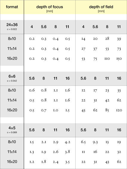
fig.12 depth of field and focus for several formats and f/stops
Both equations assume that the print magnification of the enlargement is already known, and it is good practice to document the printing scale with your printing records. The actual print magnification is simply found by cutting two notches, 1 inch apart, into the negative mask (fig.13) and measuring their projected distance on the baseboard with a ruler.
For the more mathematically inclined, print magnification (m) can also be determined from the basic dimensions of the enlarger setup and calculated as:

where ‘u’ is the lens-to-paper distance, ‘v’ is the lens-to-negative distance, ‘a’ is the total negative-to-paper distance, ‘f’ is the focal length of the lens, while ‘m>1’ calculations are meant for enlargements and ‘m<1’ for reductions. Strictly speaking, lens distances are measured to the nodal plane of the lens, but the center of the lens will suffice as a practical substitute.
For some photographic applications, it may be of interest to adjust the enlarger setup in order to produce a specified print magnification, and, in fact, the equations below are a reverse of the above formulae.

During in-camera focusing, the zone around the subject plane (depth of field) is commonly understood as a zone of reasonable sharpness and, therefore, as an extension to what theoretically is only a plane of focus. On the other side of the imaging path, the depth of focus at the camera’s film plane is typically considered to be a tolerance band for mechanical focusing inaccuracies. While the former is true, the latter is not entirely the case. As seen in fig.14a, any focus inaccuracy at the film plane will take away from the depth of field, because any deviation from the theoretical film plane position will push subject detail, recorded at the threshold of sharpness, into defined fussiness.
Similar is true when enlarging the negative (fig.14b). Any subject point, captured at the threshold of sharpness, is recorded on the negative as a small fuzzy disc with the same diameter as the circle of confusion. During negative projection, this detail must line up exactly with the theoretical negative plane or the small disc will ‘grow’ beyond the boundaries of the circle of confusion and into obvious unsharpness.
Nevertheless, just as the depth of field provides a zone of sharpness around the subject plane when recording the subject on film, it also provides a zone of sharpness around the baseboard when projecting the negative with the enlarger. As seen in fig.11, this can be used to tilt the baseboard within limits, without losing reasonable sharpness, and allowing correction of minor perspective distortions in the negative. In practice, the image center is brought into focus at full aperture, and the lens is stopped down until the entire image appears to be in focus. You can use the table in fig.12 to estimate the available depth of field for several formats and apertures.
The Scheimpflug Principle
The Austrian cartographer and sea captain Theodore Scheimpflug (1865 - 1911) is credited with the discovery of the optical relationship, which now carries his name. If a camera is adjusted so the film, lens and subject plane intersect in a single line, then everything in the subject plane will be in perfect focus. View cameras can be adjusted to take advantage of the Scheimpflug principle, but cameras with fixed film and lens planes cannot. Therefore, any perspective distortion unavoidably becomes a permanent part of the negative and can only be corrected in the darkroom.
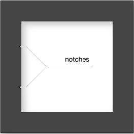
fig.13 The actual print magnification is simply found by cutting two notches, 1 inch apart, into the negative mask and measuring their projected distance on the baseboard with a ruler.

fig.14a Any subject point, captured on film at the threshold of sharpness, is recorded as a reasonably sharp fuzzy disc the size of the CoC.

fig.14b Negative detail as large as the CoC must exactly line up with the theoretical negative plane, or it is not resolved in the print. Only perfectly sharp negative detail can benefit from the enlarger’s depth of focus.
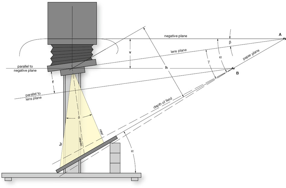
fig.15 Many enlargers allow only tilting of the lens plane, but with the help of a tilted easel, converging lines can be completely corrected using the Scheimpflug principle. This results into a projection geometry, which is identical to that of a fully adjustable enlarger, as seen in fig.17.
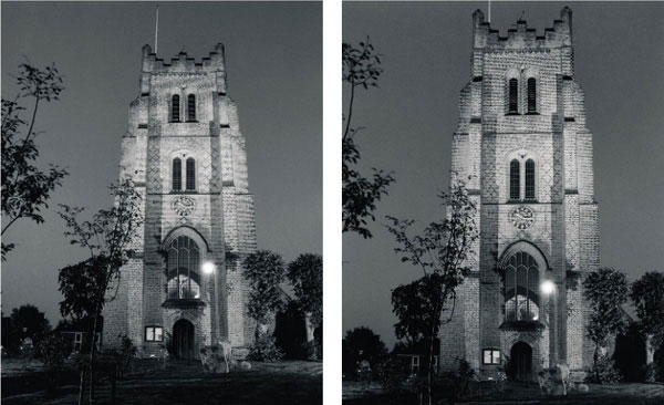
fig.16 This photograph of Ingatestone Church in Essex, UK was taken with a 35mm Canon SLR. In order to get the entire structure into the frame, the camera had to be pointed upwards, creating unwanted, but unavoidable, perspective distortion and converging lines, as seen in the straight print on the left. The corrected print on the right was made from the same negative, but the perspective distortion was corrected until the vertical lines of the church tower appeared to be parallel. In the upper half, the actual print was gradually burned-in to compensate for the exposure loss caused by the head tilt.
(images by Paul Robbins)
fig.16a converging lines not corrected
fig.16b converging lines corrected

fig.17 Professional enlargers feature full ‘Scheimpflug’ correction capabilities similar to view cameras. If such an enlarger is adjusted so the negative, lens and paper planes intersect in a single line, then the entire image will be in perfect focus. This technique eliminates perspective distortions, also called converging lines, at the printing stage. The setup involves a three-step process and may require some exposure correction on the ‘near’ and ‘far’ side.

fig.18 These two tables aid in determining the initial lens tilt ‘β’ (top) and exposure correction according to the angle between lens and paper ‘γ’ (bottom). Measure the lens to paper distance ‘h’ and the head tilt ‘α’. Find the lens tilt ‘β’ for your focal length in the top table. Calculate the angle between lens and paper from γ=αβ, and use the bottom table to find the exposure correction, relative to the centerline, in 1/12-stop increments for the near and the far side of projection, depending on your enlarging lens’ angle of coverage ‘δ’.
Some enlargers are equipped to fully support the Scheimpflug principle. If the enlarger is adjusted so the negative, lens and paper plane intersect in a single line, then the entire projected image will be in perfect focus. In the same manner as view cameras, this technique is used to eliminate perspective distortions, also known as converging lines (fig.16). A professional setup (fig.17) permits tilting of negative and lens plane independently and involves a three-step process.
1) Raise the enlarger head to ‘h’ to get the desired print size and focus.
2) Tilt the enlarger head to ‘α’ until the perspective distortion is eliminated and, otherwise, converging lines appear parallel. Refocus the image center, and estimate the location ‘A’ of the theoretical intersection between negative plane and paper plane.
3) Now, use fig.18 to estimate and adjust the angle of the lens plane to ‘β’ until it also intersects at ‘A’. Check with a focusing aid, and make the necessary correction to the lens plane until corner-to-corner focus is achieved.
It takes a bit of experience to get the last step correct, but estimating the initial lens plane adjustment can be made easier using the top table in fig.18. Unfortunately, this leaves yet another problem. The distance between negative and paper is greater on the far side than it is on the near side. This gradually increases the magnification towards the far side and corrects the perspective distortion, but it also creates uneven paper illumination. Depending on the angle between lens and paper (γ= α β), and the coverage of the lens, this difference of illumination may be significant and easily visible in the final print. A gradual burning down from the near towards the far side will correct for the light loss. A test strip will determine the amount of exposure correction required, or you can use the bottom table in fig.18 as a starting point.
Unfortunately, few enlargers feature the flexibility to adjust negative and lens plane independently, but many allow tilting of the lens plane, as seen in fig.15. In this case, tilt the easel, while the negative is projected onto the paper, until the converging lines appear to be parallel. This will throw the image out of focus, but tilting the lens plane will correct it. Correct lens tilt and focus until the entire image is in perfect focus. At that point, the projection geometry is identical to that of a fully adjustable enlarger, with the same need for exposure correction. This setup is less convenient than the enlarger adjustments in fig.17, and precise easel tilt is not always possible, but it is still a big help in correcting converging lines.
Exposure Height and Exposure Correction
Whenever the enlarger head is raised or lowered, and the negative magnification is changed, print exposure must be corrected. In ‘Tables and Templates’, you will find a chart to determine the magnification of your enlargement and another to estimate the exposure compensation required to accommodate a change in enlarger height. Strictly speaking, projected print exposures fail to follow the inverse-square law, but they follow the inverse square of the lens-to-paper distance if the paper reciprocity failure is ignored, in which case, a new theoretical exposure time (t2) is given by:

where ‘u1’ and ‘u2’ are the old and new lens-to-paper distances, ‘m1’ and ‘m2’ are the old and new magnifications, and ‘t1’ is the old exposure time.
Both charts in the appendix illustrate the optical relationships and eliminate the need for any calculations. Of course, if you are using a darkroom meter to measure print exposures anyway, you probably never need the charts or the math to ascertain a new exposure time when changing the enlarger height.
A Sharper Image
The recommendations in this chapter have covered all fundamental variables of print sharpness, as they exist in the darkroom. A well-aligned, stable and undisturbed enlarger, holding a flat negative and projecting it with a well-focused, high-quality lens, at its optimum aperture setting, onto motionless flat paper, will result in the sharpest print possible.
Other Darkroom Equipment
A few useful tools, making darkroom work a lot easier and more consistent
Following on from our overview of fundamental and useful image-taking equipment, we have several items that we both consider helpful for film and print processing. Before we proceed, it is worth mentioning the obvious fact that better equipment does not necessarily lead to better results. Fancy equipment cannot replace the skill of successful image composition or a thorough understanding of the underlying principles of photography, and it cannot make up for the lack of experience. Before one succumbs to temptation, one should realize that, unless you apply a little self-discipline, the variability introduced by any number of physical or human deviations will undermine the benefits of most equipment upgrades. This does not presume a darkroom should take on the mantle of a rocket-science lab, but a little consistency, record taking and patience offer far more benefits than the latest-and-greatest electronic equipment.
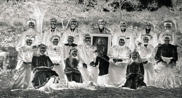
(image courtesy of the Billericay Library, Essex, UK)
Darkrooms are creative and practical environments. Their designs and equipment differ according to individual working practices and preferences. Some photographers go for the most rudimentary equipment and the hands-on approach, while others prefer high-tech sophistication and mechanization. This introduction includes equipment to support both approaches. We have used all items shown here, at one time or another, and some are permanent elements of our current darkroom arsenal.
Film and Print Processing
Film Processor
For many years, we processed films by hand in a simple tank and at ambient temperatures, using an intermittent inversion technique. There is nothing wrong with this method, and, in some cases, it is actually the best way to develop a film. Stand-development to achieve the highest possible acutance is one example for the need of manual development. However, if you develop larger quantities of film on a regular basis, and you want to do it with consistency, it may be worth checking into an automatic film processor. A popular model among amateurs is the Jobo CPE-2 processor (fig.1a), which conveniently controls agitation and temperature for print and film development. It is basically a plastic tub that holds a thermostatically controlled water bath and a development tank, which is kept in motion by an alternating bidirectional rotation system.
A brand-new unit is quite expensive, but used units can be found readily for sale on internet auctions. These processors control temperature and agitation with sufficient precision to reliably develop all monochrome emulsions, as well as C41 and E6 films. The horizontal tank design, combined with rotational processing, maximizes the film capacity for a given volume of developer. Since less than half the film is submerged in chemistry at any one time, at least twice as many films can be processed with the same amount of chemicals, in comparison to the manual hand-inversion technique. Different-sized drums and film holders are available to process 1 to 12 films in sizes of up to 4x5-inches or larger.
One disadvantage of this processor design is the increased weight of the tank when filled with water. In this state, the processor is rather heavy, and dumping the water, in order to empty the tank, can be difficult and a strain on weak backs. Fig.1b shows an effective homemade adaptation for which a hole was drilled into the tank at the bottom of a side wall. This allows a simple piece of plumbing to be fitted, and draining the tub is now as easy as removing a sealed cap.
Print Processor
A large darkroom may have plenty of space for a big sink and multiple processing trays for full-size 16x20-inch prints. However, the confinement of a smaller darkroom necessitates the use of a vertical slot processor to make processing of full-size prints possible within a small footprint.
Print processors are available in different sizes and with various numbers of slots, surrounded by a heated or unheated water jacket. One example is the Nova Quad processor (fig.2), which is manufactured by Nova Darkroom in the UK. It is a temperature controlled 16x20-inch unit with four slots to separate developer, stop bath, and a first and second fixing bath. Each slot holds about 3.5 liters of chemical solution, and the prints are held in suspension by special plastic clips, not unlike film hanging clips.
The compact convenience of vertical slot processors is hard to beat. Once filled with fresh chemistry, they are ready for immediate use and require no cleaning until these chemicals are exhausted. During that time, they are always immediately available for print processing. No need to pour chemical solutions in and out of trays or to clean up after each printing session.

fig.1a A popular piece of equipment among amateurs is the Jobo CPE-2 processor, which conveniently controls agitation and temperature for color or monochrome print and film development.

fig.1b Filled with water, the processor is too heavy to lift and very hard to drain, but fitting a piece of plumbing makes this as easy as removing a sealed cap.
Other advantages of this processor design are reduced chemical oxidation and limited output of chemical odor, all due to a relatively small liquid surface area on top of each slot, compared to large open trays.
Print Washer
No special equipment is required to wash fiber-base prints to archival standards. To wash a single print, all it takes is a simple processing tray, a water hose or a tray siphon, and plenty of fresh water. However, this inexpensive method is rather impractical if multiple prints need to be washed. A far more efficient way to wash a number of prints at the same time is to use a vertical print washer. They are available for different print sizes and typically feature several segregated compartments, each holding one print. At an appropriate flow rate, they provide an effective method of print washing by using a minimum amount of water. This is made possible by an ingenious water replenishment system of jets and weirs. They are the most convenient and compact way to wash multiple fiber-base prints to archival standards.
In the Nova WashmasterEco (fig.3), water is fed into the bottom of each chamber through a small jet and circulates, before falling over an internal weir into the exit pipe. This particular model features a fast drain facility, which allows contaminated wash water to be quickly replaced and has a single slot at one end to hold a hypo-clearing bath. There are similar models available for washing film, but we find it easier to just stick a hose into the development tank and dump the water a couple of times during the wash.
Water Flow and Temperature Control
Monochrome processes are not as sensitive to temperature fluctuations as their color counterparts. Even so, monochrome process uniformity is made considerably easier if a consistent source of temperature-controlled water is at hand. This is especially true for film development, but it also applies during an unattended wash of film and fiber-base papers. In a domestic environment, it can be quite a challenge to maintain constant water temperature by simply manipulating a set of manual hot and cold valves in the darkroom. Anytime hot or cold water is used elsewhere in the house, the water temperature in the darkroom quickly jumps up or down and requires an adjustment of the valves to avoid emulsion damage or incomplete washing.

fig.2 The Nova Quad is a temperature controlled 16x20-inch print processor with four slots for developer, stop bath and two fixing baths.

fig.3 Vertical print washers, such as this 16x20-inch Nova WashmasterEco, are the most convenient and compact way to wash multiple fiber-base prints to archival standards with a minimum amount of water.
One solution is to invest in an electronic temperature control valve, which automatically mixes hot and cold water to achieve the desired temperature and adjusts the mixing ratio up to 50 times a second to ensure a consistent output of water. The Hass Intel-lifaucet (fig4) is an example of such a unit. It requires little maintenance and provides a much more relaxed working environment by taking an annoying but important task off our shoulders. For example, it responds quickly enough that a toilet flushing anywhere in the house will not be noticed in the darkroom. Without this type of temperature control, temperature spikes of ±20°C are not uncommon.
Densitometer
A densitometer is an invaluable tool to objectively measure negative transmission and print reflection densities. Transmission and reflection densities can be measured in absolute or relative values, and it does not really matter which method is used, so long as all comparative readings are taken in the same manner. For relative print and negative density readings, the meter is zeroed on the clear negative or white print border. Absolute negative densities need the meter to be zeroed without a negative in the transmission path, although print reflection densities require that the meter is adjusted to a standard value with the aid of a reflection test target. Throughout this book, relative transmission and absolute reflection densities are simply referred to as transmission and reflection densities. Wherever absolute transmission or relative reflection density values are used instead, they are fully spelled out as such.

fig.4 The Hass Intellifaucet mixes hot and cold water to produce a constant-temperature water supply. It saves considerable time over trying to manually compensate for seasonal or domestic changes to the water temperature.
(image copyright Hass Manufacturing Company)
Densitometers are not absolutely necessary to make fine prints, but accurately calibrating film, paper and darkroom processes is difficult without them. Furthermore, densitometers can bring consistency to print making. After a long printing session, body and mind get tired and subjective print evaluation eventually fails. At that point, personal print requirements quickly change from looking ‘great’ to looking ‘good enough’. One way to maintain constant print quality is to measure print shadow and highlight densities with a densitometer during printing, on quickly dried samples, and compare them to a predetermined personal standard. This takes a bit more time at first, but it improves print quality, increases self-confidence and avoids sobering disappointments during next morning’s fresh-eye review.
fig.5a shows a modern densitometer, made by Heiland Electronics in Germany, and fig.5b shows an older model, made by Agfa. Both can measure reflection and transmission densities, for which the Heiland has a built-in light source, whereas the Agfa depends on an external light source, such as a light table, to measure transmission densities. The Agfa densitometer can read negatives and prints up to any size, and Heiland offers a model with removable head for the same purpose, plus alternatively sized apertures for different negative formats.

fig.5 A densitometer is an invaluable tool to objectively measure print reflection and negative transmission densities. The Heiland densitometer (a) has a built-in light source, whereas the older unit from Agfa (b) depends on an external light source, such as a light table, to measure transmission densities. The Agfa densitometer can read negatives and prints up to any size, and Heiland offers a model with removable head for the same purpose, plus alternatively sized apertures for different negative formats.
Darkroom Timers and Meters
This section is predominantly an introduction of RH Designs timers and meters. The reason for that is that we own and use most of their products, many of which Chris designed, patented or wrote software for. Nevertheless, if we thought there were better products out there, we would recommend them. Taking into account that the sophistication of RH Designs products does not necessarily match everyone’s requirement and budget, we have added some alternative products, which we have used successfully in the past.
Process Timer
At the simplest level, anything counting time can be used as process timer. A regular clock or watch will do the job if nothing else is available. Ansel Adams frequently used a metronome as a process timer for his dodging and burning efforts. However, in order to achieve reasonable process consistency and to eliminate human error as much as possible, every darkroom needs a dedicated process timer.
In the US, the GraLab 300 series of timers have been popular models for decades (fig.6a). They come with plain or self-illuminated face plates, which are easily seen in the dark. They are simple and reliable backwards-counting process timers, also capable to turn enlarger, safelights or other darkroom equipment on and off as needed.
The RH ProcessMaster II is a more sophisticated process timer, able to store multiple sequences of processing steps (fig.6b). It can apply factorial development and other automatic process adjustments to ensure consistency in film and paper development by compensating for fluctuating temperatures and ageing developers. This process timer can count down in seconds or in percent with an optional pause between process steps.
Enlarger Timer
We have purposely avoided introducing ordinary linear enlarger timers in this chapter, because we have both been using f/stop enlarger timers for years and cannot recommend using any other timing concept. Although f/stop timers do not make a better print, it is hard to go back to an ordinary timer once you have used one. These timers change exposure in multiples of 1/12 stop and have, depending on the model, additional features that compensate for paper reciprocity, dry-down, as well as lamp delay and warm-up effects. This eases mental and physical efforts during the printing process. Once a print is made, at any exposure time, it is a simple matter to provide an extra burn-in exposure, measured in f/stops, with a few button presses. Automatic test strip exposure sequences are also generated in f/stops, using coarse or fine steps, which permits the user to determine a burn-in or fine-tuning exposure that is recorded and effortlessly reproduced at any enlargement size.
RH Designs introduced two f/stop timers to control the enlarger and optionally the safelights, first the StopClock LE (fig.7a) and later the current StopClock Pro (fig.7b). Each is able to apply exposure increments in fractions of an f/stop and calculate test strip sequences. The current model, on the right, has a number of additional features including stored exposure sequences for complex printing.
Enlarger Meter
The most accurate method to determine optimal print exposure and contrast is to prepare test strips for both. Actually looking at exposure increments, ranging from too light to too dark, is the only way to confidently select the optimum exposure time. Similar is true for selecting print contrast. However, a good and well-calibrated enlarger meter can propose near-optimum values, based on a few simple measurements. The meter utilizes the projected brightness of an image-representative shadow and highlight area to calculate print exposure and global contrast. This produces a well-exposed work print with good overall contrast in the shortest time possible. This initial work print is the foundation for any additional fine-tuning efforts, which are more effectively conducted using the proven test-strip method above. The combination of modern technology and proven technique provides the best result in the shortest amount of time.
The Ilford EM10 (see fig.8a) is a good, entry-level, low-budget meter. As with all other enlarger meters, it must be calibrated for each paper first, but afterwards, it predicts optimum exposure times with ease and reasonable accuracy. This timer cannot be beat when it comes to value for money. However, we prefer enlarger meters with f/stop-timing capability. Figures 8b&c show the ZoneMaster II and the Analyser Pro from RH Designs. Both meters use a remote spotmeter to measure several points on the projected negative and reference them against the meter’s built-in grayscale. This patented grayscale display allows the user to convert any desirable print tone into a particular paper exposure and contrast setting. The outcome is a quickly made but accurate work print, which serves as a sound foundation for fine-tuning further prints or as an excellent product for less critical applications.
The ZoneMaster II is a separate meter, and consequently, the exposure information must be passed over to an enlarger timer. This can be done manually, or this stand-alone unit can be connected to any StopClock via a cable. The Analyser Pro combines the meter function with an f/stop timer into one unit and controls enlarger timing directly. These meters save time and material, as they help to quickly interpret a new negative. They also function as basic densitometers, by reading relative light levels when a negative is projected on the baseboard or easel.

fig.6 The GraLab 300 series of timers (a) come with plain or self-illuminated face plates to easily see them in the dark. They are simple and reliable backwards-counting process timers. The RH ProcessMaster II (b) is a more sophisticated process timer. It is able to store multiple sequences of processing steps and compensates for fluctuating temperatures and ageing developers.

fig.7 It is hard to go back to a linear timer once you have used an f/stop timer. RH Designs first introduced the StopClock LE (a), and later the StopClock Pro (b), to control the enlarger and, optionally, the safelights. Each is able to apply exposure increments in fractions of an f/stop and calculate test strip sequences. The current model has a number of additional features including stored exposure sequences for complex printing.

fig.8 A well-calibrated enlarger meter can propose near-optimum values, based on a few simple measurements. The Ilford EM10 (a) is a good low-budget meter and cannot be beat when it comes to value for money. However, we prefer the more sophisticated ZoneMaster II (b) and the Analyser Pro (c) from RH Designs with their f/stop timing capability.
Negative Focus and Paper Support
Focus Finder
It is impossible to achieve maximum print sharpness without an accurately focused projection of the negative on the baseboard. With some experience, easily recognizable image features and good eyes, this is a manageable task at reasonable magnification levels, and the depth of field around the paper plane provides a certain focus tolerance anyway. Nevertheless, many darkroom workers prefer the increased precision and confidence provided by a focus finder.
A focus finder is an optical aid to examine the virtual image, projected by the enlarger, in order to ensure that the negative image is accurately focused on the printing paper. Focus finders are designed so that the length of their optical path is exactly equal to the length of the optical path that they interrupt. This is achieved by using an angled mirror and a magnifying eyepiece to examine the reflected virtual image. The enlarger lens is carefully focused until highly magnified image detail, or the grain structure of the film, can be seen in focus.
Typical focus finders magnify the projected image 10-25 times, which, multiplied with the scale of the enlargement, is comparable to microscopic magnification levels. This explains why focus finders are also referred to as grain focus finders. The quality of a focus finder depends on its dimensional stability. We, consequently, discourage the use of inexpensive plastic models.
The MicroSight, made by Bestwell Optical, is a low-budget, 25x grain focus finder, featuring an adjustable eyepiece and a sturdy metal construction (fig.9a). It is a fully reliable focus finder and used for the majority of our focusing needs. The Peak 2000 (Model I) is a high-quality focus finder, featuring 10x magnification, an aluminum die-cast body and precision optics (fig.9b). The major benefit of this popular focus finder is that it not only finds perfect image focus at the picture center but also at any position within the image area, allowing edge-to-edge focus checking. However, it is not a true grain focus finder, due to its limited magnification.

fig.9 A focus finder is an optical aid to ensure that the negative image is accurately focused on the printing paper. The MicroSight (a) is a reliable focus finder with sturdy metal construction. The Peak 2000 (b) features 10x magnification, an aluminum die-cast body and its unique design allows edge-to-edge focus checking.

fig.10 A printing frame is an essential accessory for contact-printing to keep the negative and print in perfect contact over their entire surface when printing digital negatives. The solid cherry-wood frame, made by Lotus View Camera, features a felted hinged back. Two strong springs lock into runners along the frame and clamp the print securely to the negative over the entire surface.
(image copyright Lotus View Camera)
A common recommendation is to use a piece of paper underneath the focus finder, simulating the missing thickness of the printing paper, for increased accuracy. This is theoretically a sound approach, but in practice, a paper-thin focusing error is just too small to create a detectable out-of-focus condition. On the other hand, if you are working with a black easel, and therefore need a piece of white focusing paper anyway, you are already focusing on the correct, theoretically perfect, image plane.
Contact-Printing Frame
Enlarging a negative inevitably reduces image quality. This effect is minimized by using the largest negative possible. Nevertheless, ultimate image quality is only achieved if enlarging is avoided altogether, and the negative is brought into direct contact with the printing paper and firmly held in place during the exposure. Contact printing produces a print the same size as the negative.
For occasional contact printing, firm contact between negative and paper can be accomplished by weighing down both with a heavy glass plate. But, a dedicated printing frame is an essential accessory for more frequent contact-printing needs. The frame keeps the negative and print in perfect contact over their entire surface when printing digital negatives or when using so-called ‘alternative processes’.
Traditional printing frames are deceptively simple to make, and some darkroom workers will choose to make their own. Alternatively, sturdy frames, crafted from hardwood, are still available from a few specialists. The frame shown in fig.10 is manufactured by Lotus View Camera in Austria. It has a solid cherry-wood frame for strength and features a felted hinged back to support printing by inspection. Two strong springs lock into runners along the inner sides of the frame and clamp the print securely to the negative over the entire surface.
Enlarger Easel
At its simplest level, an enlarging easel holds the paper flat and allows accurate positioning. Several master printers get away with using nothing but a thick wooden board and a few pieces of double-sided tape to hold the paper in place. More elaborate easel designs offer leveling feet, alignment grids, adjustable masking and pen lining.

fig.11a The color of the easel surface is of some practical importance. During the exposure, some light is transmitted through the paper, reflected by the easel and added as unwanted exposure from the back. This has an effect on print exposure and contrast.
fig.11b A black easel eliminates unwanted print fogging and avoids tell-tale signs of printing records, written on the back of the paper prior to the exposure.

fig.12 With a few simple steps, you can add a precision pen line to your print. What you need is a steel baseboard with a radiating grid to center the prints, a set of standard-size print masks with slightly undersized inserts, both cut from opaque plastic, and a couple of magnets. In (a), the plastic mask is centered on the grid, and the enlarger is set up for this enlargement size. In (b), the paper is slid under the mask, and a few magnets are used to secure mask and paper. After the final print exposure has been made, the undersized insert is placed into the aperture of the mask and pushed into the lower left-hand corner (c). At this point, a flash light is used to burn in half of the pen line. This is repeated with the insert in the upper right-hand corner to finish the pen line (d). Ralph does not like the constraint of standard enlargement sizes, but Chris prefers consistency between images likely to be shown together. Not every print requires a fine pen line around the image, but especially with high-key images and images with distracting but image-relevant features close to the image border, pen lines provide a visual framing effect and ‘hold’ the image together)
The color of the easel surface is of some practical importance. Photographic paper is not completely opaque. Typical double-weight paper transmits between 6-12% of the light it receives. A bright-white easel reflects 80-90% of that back into the paper and adds unwanted exposure from the back. On average, this is similar to 1/12 stop fogging exposure. Fig.11a illustrates the effect on print exposure and contrast. On a white easel, print shadows and midtones receive appreciably more exposure, compared to a black easel, which raises the print contrast slightly. In practice, this is of little concern, unless differently colored easels are used during the printing session. However, if one has developed the habit of recording exposure and contrast data on the back of the paper, and does so prior to the print exposure, tell-tale signs of these records may be noticeable in uniform midtone regions.
Ralph prefers a plain black easel for its simplicity (see fig.11b). Chris uses a steel-based pen-lining easel and pre-cut plastic masks and inserts (fig.12). After the final print exposure, the undersized insert is placed in opposite corners of the mask’s aperture, which allows a fogging exposure to create a perfect thin black pen line (fig.13). The image sequence in fig.12 shows the principle and the equipment required. It will enable practical photographers to make their own. The alignment grid is a great help when centering prints and checking verticals in the image.
Other Printing Tools
Paper Flasher
Flashing and fogging prints can be accomplished in a number of ways. They require a low-level, controllable and uniform light beam over the enlarger easel. Some darkroom workers dedicate an old enlarger for the purpose, while others use a diffuser, in the form of a polystyrene cup, over the enlarger lens.
The RH Designs PaperFlasher II (fig.14) is a sophisticated way to flash and fog prints. It combines an f/stop timer with a low-level, diffused light source, which can be positioned centrally or locally over the easel. Its built in test-strip mode enables one to precisely select the correct exposure level. The light unit has a removable outer diffuser, which, when removed, increases the light level for print fogging or burning in pen lines. The two light levels are fixed for convenient consistency and accuracy.
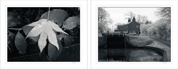
fig.13 A pen line is a thin, black line, marking the image periphery. It is added during or after darkroom exposure and helps to frame the image, keeping the picture together as one unit and preventing the viewer’s eye from drifting off the image into the border. Some images benefit from a pen line more than others. The image on the left is sufficiently self-contained to work without it, but the blank sky in the image on the right clearly benefits from the added pen line.
(images by B. Woodhouse)
Darkroom Torch
Every now and again, you need an additional small light source in the darkroom. It should be portable and sufficiently safe, so that brief exposures do not fog film or paper, but it must be bright enough to accomplish all the special tasks for which regular safelights are too bright or only provide insufficient illumination. Imagine the following examples: After inserting the film into the reel and placing it into the development tank, you accidentally drop the lid. It can be a challenge to find the lid in the dark, during which time the film is left unprotected. Or, you might be in the middle of a complex printing sequence when you start looking for that special, custom-made dodging tool, only to realize that it still must be in one of those boxes under the sink.

fig.14 The PaperFlasher II is a sophisticated way to replace a polystyrene cup for flashing and fogging prints. It combines an f/stop timer with a low-level diffuse light source and includes a built-in test-strip mode.

fig.15 Every now and again, you need a darkroom torch. Modern LED technology makes it possible to limit their light output to a narrow wavelength, outside the sensitivity range of film and paper.
A darkroom torch is the perfect tool on these occasions, because turning on the lights is not a viable option. Several models are shown in fig.15, and modern LED technology makes it possible to limit their light output to a narrow wavelength outside the sensitivity range of film and paper. They are all handheld, battery-operated devices. The Ilford model is designed for color and monochrome papers, the RH Designs model (bottom right) features a push button and is safe with most monochrome materials, and the bicycle tail light (top right) was successfully diverted from its intended use.
Pin-Registration and Masking Kit
Accurate pin registration is essential for any of the precision masking techniques described in this book. It is possible to line up a 4x5-inch negative and mask, by eye under a loupe, and secure the sandwich with a piece of tape, but with any smaller format, human tolerances take hold and a mechanical aid to accurately align the two is required. In today’s market, however, the choices are very limited. The Precision Pin-Registration Carrier System from Lynn Radeka Photography is designed for making prints with unsharp or contrast controlling masks (fig.16). It fits most enlargers and is composed of a machined aluminum frame, which fits snugly in the enlarger’s negative stage. The frame acts as a receptacle for the accompanying pin-registration glass carrier, which slides into the frame and comes to a positive, perfectly registered stop without any lock knobs or latches. In addition to making and printing with masks, it can also be used for double-printing techniques, and it is sufficiently precise to allow printing with separation negatives.

fig.16 The Precision Pin-Registration Carrier System from Lynn Radeka Photography is designed for making and printing with unsharp or contrast controlling masks, and it can also be used for creative double-printing techniques.
Review Questions
1. Which of the following statements is true?
a. the effective speed of a leaf shutter changes with aperture setting
b. a tripod makes no difference with shutter speeds below 1/f s
c. darkroom walls should be painted flat black
d. all photographic papers require the same safelight filter
2. How do condenser and diffusion enlargers affect print quality?
a. print sharpness is independent of enlarger type
b. diffusion enlargers create smoother highlights
c. condenser enlargers are sharper but highlight dirt and dust
d. condenser enlargers block up shadow detail
3. How can print sharpness be optimized?
a. by using a glass-less negative carrier
b. by avoiding below-the-lens filters
c. by keeping exposure times below 10 s
d. by using a perfectly aligned wall-mounted enlarger
4. How do you get the best performance from an enlarging lens?
a. nothing to worry about, all enlarging lenses are good
b. by using its optimum aperture
c. by stopping it all the way down
d. by only buying name brand lenses
5. What else can be done to significantly improve print sharpness?
a. use a vacuum easel to keep the paper as flat as possible
b. use the Scheimpflug principle when correcting for converging lines
c. place a piece of paper under the focusing aid
d. use the smallest aperture possible to extend the depth of field
6. Which of the following statements is true?
a. f/stop timing does require an f/stop timer
b. archival washers are more effective than tray washing
c. a good enlarger meter eliminates the need for test strips
d. the color of the enlarger easel can negatively affect print quality
7. How does a pen line affect print quality?
a. should be added consistently
b. should not be added, because it negatively affects print longevity
c. it frames the image and keeps the pictures together as a unit
d. only useful for unframed prints