Human Body Communication for a High Data Rate Sensor Network
Jung-Hwan Hwang and Chang-Hee Hyoung, Electronics and Telecommunications Research, Daejeon, Korea
As wearable sensors such as health-monitoring sensors become necessities in our lives, there is a growing need for more effective connection methods that enable such sensors to communicate with each other or with peripheral devices. A wired connection method has frequently been used for on-body wearable sensors, but it inconveniences users due to the requirement of connection cables. Also, it is practically impossible to connect in-body wearable sensors such as an implantable pacemaker with a connection cable. Wireless connection presents an appealing alternative, but still needs improvements with respect to power consumption, hardware costs, and frequency regulation. To overcome the disadvantages of wired and wireless methods, researchers have proposed human body communication (HBC). In HBC, the human body, whose tissues have the features of a lossy dielectric material, is used as a transmission channel to transmit data from one device to another, allowing devices to communicate without wired or wireless connections. Wearable sensors can communicate with each other using the human body as a transmission channel, or a user can transmit data in wearable sensors to a peripheral device such as a desktop computer simply by touching the device. The IEEE 802.15 working group for the body-area network (BAN) has recently published a standard for a physical layer (PHY) using HBC. This chapter covers the fundamental aspects of HBC from the transmission channel and communication hardware to its commercialization and related challenges. It consists of four sections: (1) the channel properties of the human body, (2) the transmission scheme of HBC, (3) the analog front-end for HBC, and (4) the commercialization of HBC and related challenges.
Keywords
Human body communication; channel model; electrode; electric field; electromagnetic environment; analog-front end; transmission scheme; Walsh code; spreading; clock and data recovery
1 Capacitive-Coupling Communication Through Human Body
Human body communication (HBC) was first proposed by Zimmerman [1–3] as a novel communication technology to exchange data between electronic devices in body area networks (BAN). Its application is not limited to data transmission but extended to power transmission [4], in which electronic devices receive power required for operation simultaneously with data. Unlike wired and wireless methods, HBC uses a capacitive-coupling transmission channel, in which both transmitter and receiver are capacitively coupled by an electric field passing through the human body. The transmitter then modulates the electric field according to data to be transmitted; the receiver detects the modulated electric field and recovers the transmitted data [2]. Such capacitive coupling is possible because the human body is composed of various tissues having a high dielectric constant. The transmitter and receiver both use an electrode instead of an antenna. The electrode is attached to the human body and forms the modulating electric field at the transmitter or detects the modulated electric field at the receiver.
Compared to HBC, a wired connection has advantages of a higher data transfer rate and easiness of establishing a connection. User’s behavior, however, is constrained by cables that are easily tangled. A wireless connection removes such a constraint, but has an inherent limit in terms of power consumption because it modulates a baseband signal onto the carrier frequency in order to transmit data through the air. Wireless devices should have their own energy source to operate, and a wireless solution consumes more power to transmit and receive the information. In a wireless connection, the transmitted signal experiences a path loss caused by various factors, such as free space loss, refraction, diffraction, and absorption over the channel. Such a propagation environment degrades the quality of the received signal. In addition, a wireless connection is more complex to configure and establish.
HBC has the advantages of both wired and wireless connection methods. HBC uses a capacitive-coupling transmission channel inside the human body; hence, it does not require any cable to connect devices and is less sensitive to the propagation environment outside the human body. A user can configure a communication network simply by touching devices, and it provides an intuitive service, in which a complicated procedure for a network setup is not required. A physical layer (PHY) for body area networks has been recently standardized by the IEEE 802.15 working group [5]. In addition to NB (narrow band) and UWB (ultra-wide band) wireless communications, HBC is included in the standard as a scheme for short-range communications. In the IEEE standard, data to be transmitted through the human body is spread over the selected frequency domain using a group of digital codes without a continuous frequency modulation; hence, HBC has lower circuit complexity and lower power consumption. A comparison of the HBC PHY in [5] with other PHYs for wireless communications is shown in Table 1.
Table 1
| Market Name | HBC | ZigBee | Bluetooth | Wi-Fi |
| Physical Layer Standard |
802.15.6 | 802.15.4 | 802.15.1 | 802.11n |
| Frequency Band | 5~50 MHz | 900 MHz | 2.4 GHz | 2.4 / 5 GHz |
| 2.4 GHz | ||||
| Modulation | Frequency Selective Digital Transmission | Direct Sequence Spread Spectrum | Adaptive Frequency Hopping Spread Spectrum | Orthogonal Frequency Division Multiplexing |
| Data Rate | 2 Mbps | 250 kbps | 1 Mbps | 150 Mbps |
| Range | <3 m | 100 m | 10 m | 100 m |
| Power | Very low | Low | Moderate | High |
| Complexity | Very simple | Simple | Complex | Very complex |
| Set-up time | <100 ms | 30 ms | Few seconds | Few seconds |
| Ease of use | Easy | Easy | Normal | Hard |
| Application Focus | Body area network | Sensor networks, industrial control | Cable replacement | Local area networking |

2 Channel Properties of Human Body
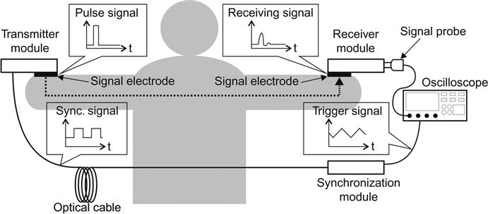
Figure 1 shows the basic principle of HBC. Each transmitter and receiver has a signal electrode that is attached to the human body. In HBC, an electric field is formed between a transmitter and receiver for a capacitive coupling between them. For this, the signal source of the transmitter creates a voltage difference between the signal electrodes and simultaneously at the load of the receiver. Also, another voltage difference is formed between the ground planes of the transmitter and receiver, which makes the sum of the voltage differences on the closed loop equal to the voltage by the signal source, where the closed loop is formed by the signal source at the transmitter, the load at the receiver, and the coupling inside the human body and in the air, respectively, with one coupling between the signal electrodes through the human body and another coupling between the ground planes through the air. Finally, the voltage difference between the signal electrodes causes a small amount of the current inside the human body due to the electric field formed inside the human body. The human body is composed of various tissues that collectively have the properties of a lossy dielectric material (i.e., each tissue has a dielectric constant and conductivity depending on the signal’s frequency [6]). The current inside the human body is composed of two types of components: the displacement and the conductive currents, which are respectively related to the dielectric constant and the conductivity. The tissues of the human body have a relatively large dielectric constant [6], especially at the low-frequency band (< 100 MHz) used by HBC [7–11]. Therefore, the displacement current mainly contributes to the transmission of the electrical signal through the human body. In HBC, the electrical signal at the low-frequency band is transmitted over a short distance within the human body through a material having a high dielectric constant. Thereby, an HBC channel has a unique property: the transmission of the electrical signal is strongly affected by the structure of the electrodes and by the electromagnetic environment outside the human body.

3 Effects of Electrode’s Structure
In HBC, a transmitter capacitively coupled with a receiver modulates an electric field and the receiver detects the modulated electric field. This is equivalent to generating and detecting a voltage difference: a voltage difference is generated on the surface of the human body by a transmitter and then detected by a receiver [11]. The generation of the voltage difference and its detection are made possible with an electrode attached to the human body [12–15]. An electrode can have an adhesive material on its surface like a disposable ECG electrode or a metal surface for a simpler implementation. In the case of a metal surface, it can be held in contact with the human body with an attachment aid like a rubber band or be touched by hand when necessary. The electrode should have small contact resistance to minimize signal loss. HBC uses two types of electrodes: a signal electrode and a ground electrode as shown in Figure 1. Each signal electrode of the transmitter and receiver is connected to a signal source in the transmitter or a load in the receiver, while each ground electrode is connected to the ground plane of the transmitter or receiver. The structure of the electrodes affects the transmission of the electrical signal through the human body. In particular, the attachment of the ground electrode onto the body affects the channel’s signal loss as it increases or decreases the signal loss that the electrical signal experiences as it is transmitted through the human body [12–14,16,17].
In two studies ([13,14]), the signal loss was shown to decrease when the ground electrode of the transmitter was attached to the body, but the measured results in another study [17] showed that the signal loss increases with the attachment of the ground electrode. Also, the decrease of the signal loss caused by the attachment of the ground electrode itself decreases gradually as the transmission distance between the transmitter and receiver increases [14]. The transmitter can be located at the wrist or the finger according to the HBC application, and the location of the transmitter also affects the operation of the ground electrode. Figure 2 shows the change in signal loss at 30 MHz caused by the ground electrode when the transmitter is located at the wrist and the finger [17]. As shown in Figure 2(a), the measured signal loss decreases as the ground electrode is attached to the body when the transmitter is located at the wrist. However, as shown in Figure 2(b), the ground electrode has the opposite effect on the signal loss when the transmitter is located at the finger; the signal loss increases as the ground electrode is attached to the body. Such various effects shown by the ground electrode on the signal loss can be analyzed using the distribution of the electric fields inside the human body.

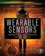
Figure 3 shows the distribution of the electric fields near the transmitter, in which the electric field was simulated using a rectangular parallelepiped human model. The simulation model has a cross-section of a different size depending on the position to separately model the wrist and finger. As shown in Figures 3(a) and 3(b), the electric fields inside the human body are distributed in different directions according to the position due to the field coupling from the signal electrode to the ground plane. When x<–2 cm, the fields inside the body are distributed in a direction opposite to that of the receiver (i.e., the fields direct the ground plane) because the fields are strongly coupled with the ground plane. However, as the distance from the transmitter increases, the coupling with the ground plane becomes weak; hence, the fields inside the body are distributed in the direction of the receiver, as shown when x>0 cm. The degree of the field coupling with the ground plane is dependent on the location of the transmitter. When the transmitter is located at the finger, the volume of the body near the transmitter is small because the finger is much thinner and shorter than the wrist. This means that the volume of the dielectric material on the coupling path to the ground plane is small. In this case, the coupling with the ground plane becomes so weak that the fields are distributed easily in the opposite direction of the ground plane, i.e., in the direction of the receiver. When the ground electrode is attached on a larger part of the human body, the distribution of the electric fields takes the form shown in Figures 3(c) and 3(d).
In comparison with the distribution shown in Figures 3(a) and 3(b), more fields are distributed in the direction opposite to the receiver because the ground plane is in contact with the body through the ground electrode and, accordingly, the coupling with the ground plane becomes stronger. Thereby, the net electric field in the direction of the receiver is formed inside the human body while the field strength depends on the canceling effect between the fields of different directions. The increase of the field coupling causes an increase in the voltage difference between the signal and ground electrode and an increase in the output current of the transmitter (i.e., the output current of the signal source). The output current increases from 1.8 mA to 8.9 mA for the wrist and from 1.4 mA to 5.0 mA for the finger. When the transmitter is located at the wrist, the increase in the output current is larger because the coupling with the ground plane through the ground electrode is stronger due to the large volume of the dielectric material on the coupling path to the ground plane. The large increase in the output current caused by the attachment of the ground electrode increases the net electric field in the direction of the receiver even with the canceling effect, and the increase of the net electric field increases the voltage difference on the surface of the human body. This decreases the signal loss, as shown in Figure 2(a). However, the attachment of the ground electrode does not cause such a large increase in the output current when the transmitter is located at the finger. Therefore, the net electric field in the direction of the receiver decreases due to the canceling effect and the signal loss increases accordingly, as shown in Figure 2(b).
Considering these results, the ground electrode of the transmitter affects the signal loss through two effects. The first is the effect of the increase in the output current and the second is the increase in the field coupling of the electric fields with the ground plane. When the ground electrode of the transmitter is attached to the human body, the output current increases. When the output current is very large, there is a corresponding increase in the net electric field in the direction of the receiver and, consequently, a decrease in the signal loss [13,14], as shown in Figure 2(a). However, the ground electrode also increases the field coupling with the ground plane, causing an increase in the electric field of the opposite direction and its accompanying canceling effect. Thus, when the increase of the output current is small, the net electric field in the direction of the receiver decreases and the signal loss increases accordingly [17], as shown in Figure 2(b). Also, the canceling effect lowers the decreasing effect of the signal loss due to the attachment of the ground electrode as the transmission distance increases [14].
3.1 Effects of the Electromagnetic Environment Outside the Human Body
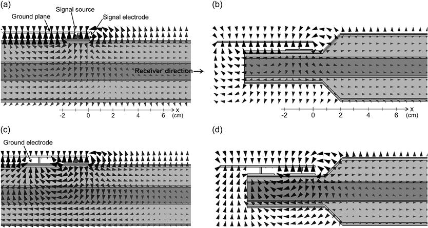
The human body is composed of many tissues which have a high dielectric constant, in the low-frequency bands [6], especially bands under 100 MHz, which can be easily coupled with the human body due to their short effective wavelengths inside the body [18–20]. Outside the human body, various types of electronic devices emit electromagnetic waves in a low-frequency band [17]. The emitted electromagnetic waves are coupled with the human body due to its antenna function, and the coupled waves then generate an interference signal inside the body, so the receiver receives an interference signal caused by the electromagnetic environment outside the human body along with a data signal transmitted from the transmitter. To illustrate this effect, the interference signal received at the receiver was measured in various electromagnetic environments, as shown in Figure 4. A subject was exposed to a general electromagnetic environment like that shown in Figure 4(b), while the receiver’s signal-electrode was attached to the arm of the subject. The interference signal caused by the human body’s antenna function was then measured at the signal electrode using the measurement setup shown in Figure 4(a).
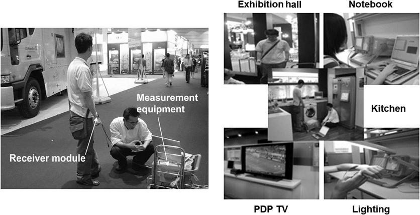
Figure 5 shows examples of interference signals measured inside buildings and on a subway, in which power of the interference signal is presented in the frequency domain. The interference signal does not have significant power at some measurement sites inside buildings, but otherwise it has high power over a wide-band region, as shown in Figure 5(a). Unlike the building environments, the interference signal has high power at most measurement sites inside the subway, and the high power is distributed under 30 MHz due to the high-voltage pantograph collector used on the subway system. The interference signal in HBC has a dynamic property such that its power and frequency change depending on the location; however, the interference signal is distributed mainly in the low-frequency band used by HBC. Any electronic device emitting an electromagnetic wave in the low-frequency band can be a source of interference. Therefore, the transmitter for HBC also is a significant source of interference; an electrical signal transmitted at one user’s transmitter for HBC is emitted outside the human body in the form of an electromagnetic wave due to the antenna function of the human body, and the emitted electromagnetic wave is then coupled with the human body of another user nearby. In this case, the power of the interference signal is dependent on the number of HBC users and the distances between each user. This is especially similar to that of the receiving signal for HBC when users are in close proximity to each other [18]. Therefore, the interference signal in HBC can have high power in the same frequency band occupied by the electrical signal transmitted through the human body, causing severe degradation of the bit error rate (BER) performance, a metric indicating the number of errors in the received data stream.

3.2 Channel Model for Human Body Communication
A channel model is required to design a transmission scheme and an analog front-end for HBC. The IEEE standard for HBC has been published [5], and its PHY structure is based on the channel model presented in an earlier study [21]. The channel model is composed of a channel filter and an interference signal generator1, as shown in Figure 6. The channel filter represents the signal loss experienced by the electrical signal as it is transmitted through the human body. An electrical signal to be transmitted through the human body is filtered by the channel filter and the interference signal generated from the interference signal generator is then added to the filtered signal. After the thermal noise is added, the channel’s output signal is obtained.

Numerous researchers have studied signal loss by the human body [22–25]. For an accurate measurement of signal loss, it is important to isolate the grounds of the transmitter and the receiver from the earth ground, as the coupling between the ground planes strongly affects the signal loss. However, in previous research, the measurement equipment was connected to the earth ground [22,23], or abnormally large ground planes were used to measure the signal loss [24,25]. In order to measure the signal loss while maintaining an isolation condition between the ground planes, the measurement setup shown in Figure 7 is used [26]. The transmitter module, powered by a battery, generates the pulse signal, and the generated pulse signal is transmitted through the human body. The transmitted pulse is received at the receiver module and measured using the oscilloscope. The pulse signal has a very short width and hence has a high-frequency component to obtain the signal loss over a wide frequency band. The transmitter module simultaneously generates a signal synchronized with the pulse signal, and this synchronization signal is optically transmitted to the synchronization module using the optical cable. The synchronization module restores the synchronization signal and then triggers the oscilloscope whenever the pulse signal is generated at the transmitter module; hence, the receiving signal at the receiver module can be measured with the transmitter and receiver modules synchronized. Also, the isolation condition between the ground planes is maintained during the measurement, as the two modules are optically, not electrically, connected to each other. The pulse signal and the receiving signals are transformed into the frequency domain using the Fourier transform, and the signal loss is then computed by subtracting the receiving signal from the pulse signal in the frequency domain. The impulse response of the channel filter in Figure 6 is obtained like Eq. (1) after the transformation of the computed signal loss into the time domain [21]:
(1)
Here, hR(t) is a reference impulse response, and Ch is a coefficient related to sizes of the ground planes and distances between the transmitter and receiver, as follows:
(2)
 (2)
(2)In the above equation, GT and GR are the ground plane’s size in cm2 at the transmitter and receiver, respectively. Additionally, dair and dbody are the distances related to the coupling between the transmitter and receiver through two mediums, as shown in Figure 1; dair is the distance in cm between the transmitter and receiver through air; and dbody is that between the transmitter and receiver through the human body. Ch is valid only when 10 cm2≤GT, GR≤270 cm2 and 10 cm≤dair, dbody≤200 cm. The reference impulse response is an impulse response when the coefficient Ch is equal to 1; it is expressed as follows:
(3)
Each HBC user has different physical parameters related to the channel; these account for various body size and component ratios of body tissues, such as fat and muscle. The signal loss in HBC is affected by these physical parameters; hence, each user has a different amount of signal loss. Av in Eq. (3) is a random variable used to represent this type of variation in the signal loss; it follows the Gaussian distribution with a mean of 1 and a variance of 0.162. A, tr, t0, xc, and w are the constants related to a shape of the reference impulse response [21].
At the transmitter, the electrical signal before being transmitted through the human body is filtered by mask filtering to remove harmonic components and possible interference in other frequency bands [5], thus occupying a narrow band of about 6 MHz. The interference signal is modeled only over the occupying band and can therefore be approximated with the additive white Gaussian noise, which has a frequency-independent power. The measured interference signal has the Gaussian distribution; this is reasonable because multiple electronic devices, including HBC transmitters, emit electromagnetic waves, and these waves amount to an interference signal at the receiver. After the summation of independent random variables, it follows the Gaussian distribution according to the central limit theorem. The interference signal has a different variance according to a location where HBC is used; hence, the interference signal generator from [21] is modeled with maximum variance of the interference signal, for which the measured maximum variance was found to be 2.55×10⁻⁵.
4 Transmission Scheme of Human Body Communication
The IEEE 802.15 working group for body area networks recently published the standard for PHY using HBC [5]. The transmitter is composed of signal-generation blocks to generate a preamble, a start-frame delimiter (SFD)/rate indicator (RI), a header, a physical layer service data unit (PSDU), and a pilot signal. The signals generated in each block are added at multiplexers (MUXs) and then sent to a transmit filter to achieve compliance with the spectral mask defined in [5]. The transmitter uses the frequency selective digital transmission (FSDT) scheme; unlike general wireless communication, a baseband signal, which results from the spreading of a data signal in the frequency domain using the Walsh code and the frequency selective code (FSC), is transmitted through a transmission channel (i.e., the human body) without modulation to transform a baseband signal into a passband signal in the IF or RF band. The transmission of the baseband signal is possible because the human body supports signal transmission at a low-frequency band where the baseband signal is distributed [7–11]. The baseband signal after the transmit filter is transmitted through the human body to a receiver. BER performance at a receiver is affected by the signal loss of the channel and by the interference signal, which is generated by the electromagnetic environment surrounding an HBC user [7]. To prevent BER degradation by an interference signal, the transmitter spreads the data signal in the frequency domain before transmitting it through the human body. The data signal is spread using the frequency-selective (FS) spreader before the transmit filter, as shown in Figure 8, and the resulting baseband signal is transmitted through the human body. Serial input data is converted to a 4-bit symbol by a serial-to-parallel (S2P) converter, and each symbol is then mapped into one of the 16-chip Walsh codes according to the mapping table shown in Figure 8. Each chip in the Walsh code is then mapped into one of the two FSCs whose chip sequence starts with “0” or “1,” and it repeats “0” and “1” in the length of one FSC, as shown in the mapping table in Figure 8. This mapping table shows when each chip in the Walsh code is mapped into 8-chip length FSC. The length of the FSC is controlled according to a data rate of the serial input data to keep the chip rate at the output of the FS spreader, i.e., 42 Mcps [5]. Each Walsh code has a different fundamental frequency [8], making it possible to distribute the data signal after the spreading in a specific frequency band (i.e., to be frequency-selective) to avoid the frequency band where the interference signal is mainly distributed. Hence, the FSDT scheme has good tolerance to interference due to its frequency-selective feature along with the processing gain provided by the spreading. HBC PHY in [5], however, has not been implemented yet. Instead, an HBC modem having a similar PHY has been implemented, in which the Walsh codes are used to generate a frequency-selective data signal without FSC [8]. This section explains the transmission scheme of HBC using the HBC modem originally presented in [8].

4.1 Walsh Code
It is necessary to understand the characteristics of the spread code to understand the transmission scheme comprehensively.
The Walsh (–Hadamard) code is unique in that each non-zero code word has a Hamming weight of exactly ![]() , which implies that the distance of the code is also
, which implies that the distance of the code is also ![]() . In standard coding theory notation, this means that the Walsh–Hadamard code is a
. In standard coding theory notation, this means that the Walsh–Hadamard code is a ![]() code. The Hadamard code can be seen as a slightly improved version of the Walsh–Hadamard code, as it achieves the same block length and minimum distance with a message length of n+1; i.e., it can transmit one more bit of information per code word, but this improvement comes at the expense of a slightly more complicated construction.
code. The Hadamard code can be seen as a slightly improved version of the Walsh–Hadamard code, as it achieves the same block length and minimum distance with a message length of n+1; i.e., it can transmit one more bit of information per code word, but this improvement comes at the expense of a slightly more complicated construction.
A Walsh (–Hadamard) code is obtained by selecting as code words the rows of a Hadamard matrix. A Hadamard matrix ![]() is an
is an ![]() matrix (n is an even integer) of 1s and 0s with the property that all rows differ from other rows by exactly
matrix (n is an even integer) of 1s and 0s with the property that all rows differ from other rows by exactly ![]() positions. One row of the matrix contains all zeros. The other rows contain
positions. One row of the matrix contains all zeros. The other rows contain ![]() zeros and
zeros and ![]() ones.
ones.
For n=2, the Hadamard matrix is
(4)
Furthermore, from ![]() , the Haramard matrix
, the Haramard matrix ![]() is generated according to the relationship
is generated according to the relationship
(5)
where ![]() denotes the complement (0s replated by 1s and vice versa) of
denotes the complement (0s replated by 1s and vice versa) of ![]() . For example, the
. For example, the ![]() matrix is created as follows:
matrix is created as follows:
(6)
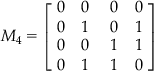 (6)
(6)Each code has a fundamental frequency despite the fact that it has many frequency components. In the case of the ![]() matrix, the first row has no transitions, and the second row has three transitions and has the highest fundamental frequency component. The third and fourth rows have one and two transitions, respectively. If the matrix is rearranged by the number of transitions, the higher the index, the higher the number of fundamental frequency Walsh codes there will be. This means that the greatest power of each Walsh code is in its fundamental frequency.
matrix, the first row has no transitions, and the second row has three transitions and has the highest fundamental frequency component. The third and fourth rows have one and two transitions, respectively. If the matrix is rearranged by the number of transitions, the higher the index, the higher the number of fundamental frequency Walsh codes there will be. This means that the greatest power of each Walsh code is in its fundamental frequency.
4.2 Frequency-Selective Digital Transmission
Data transmitted in a digital waveform can be spread over the selected frequency domain using Walsh codes. A 64-chip Walsh code is used for HBC. The 64-chip Walsh code is rearranged according to the number of transitions; hence, the index of each code corresponds to the number of transitions. For example, a code with index number 48 of the 64-chip Walsh code, W48, has 48 transitions. It is divided into four groups with 16 codes using the index of each code. The fourth subgroup of the 64-chip Walsh code has 16 codes, the highest number of transitions and thus, the highest fundamental frequencies. If it is assumed that the system uses a clock of 32 MHz, the maximum fundamental frequency is 16 MHz. The occupied frequency band of subgroup 4 of the 64-chip Walsh code in such a case is depicted in Figure 9, which shows the simplified spectrum of the fourth subgroup, the received signal that passed through the human body and the normalized noise power from the interference signal caused by an antenna function of the human body. If the codes of this group are used in order to spread a signal, the highest signal power to be transmitted exists in the fourth subgroup mainly located in the 12 to 16 MHz frequency band.

Also, as shown in Figure 9, the normalized noise power with a 5 MHz bandwidth decreases in proportion to the frequency. An earlier study [27] also reported that there is a narrow window between 10 MHz and 20 MHz in which the interference signal’s power is relatively low. In the frequency response of the human body channel under study, the signal loss in the human body channel gradually increases in proportion to the frequency up to 40 MHz. Above 40 MHz, the signal loss increases more rapidly in proportion to the frequency.
Though a conventional spread system has a wider bandwidth that resembles white noise, the transmitted signal generated with the subgroup of the 64-chip Walsh code resembles the signal modulated with carrier frequency. The output spectrum appears as the baseband signal with the 4 MHz bandwidth but modulated with a carrier frequency of 14 MHz. With a group of Walsh codes, the information is spread into the selected frequency without continuous frequency modulation using the carrier frequency. The spread spectrum has the advantage of guaranteeing the quality of communication by increasing resistance to the interference of the human body coming from various appliances. The HBC modem in work [8] makes use of 16 codes out of the 64-chip Walsh codes that have the highest fundamental frequencies, i.e., the fourth subgroup (W48~W63) in Figure 9. Figure 10 shows a block diagram of the HBC modem and the operation of the frequency-selective digital transmission. The serial input data becomes a 4-bit symbol by a serial-to-parallel (S2P) block. This 4-bit symbol becomes the index of the 16 codes out of the 64-chip Walsh codes. If the source data rate is 2 Mbps, the symbol rate is 0.5 Msps (symbols per second) after the serial-to-parallel converter. The final chip rate after the frequency-selective spreader is then 32 Mcps (chips per second). The FSDT scheme has the advantage of a high data rate and a simple architecture. A previous system [28] makes use of Manchester coding, which always has a transition in the middle of each bit period; hence, an error in transition will directly result in a bit error. However, in the FSDT scheme, the minimum distance of the 64-chip Walsh code is 32; therefore, the receiver can still decode even if 15 bits are lost. The spread baseband signal has only two consecutive identical chips, 00 or 11. As a result, its fundamental frequency ranges from 12 to 16 MHz with a clock frequency of 32 MHz. Through the use of the 16 spread codes with the highest fundamental frequencies, the baseband appears to be modulated with a carrier frequency of 14 MHz. The FSDT scheme can be implemented without a digital-to-analog converter (DAC) at the transmitter, an analog-to-digital converter (ADC) and circuit block related to the radio frequency (RF). This ensures extremely low power consumption and implementation in a small size.
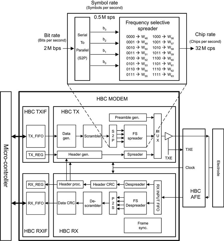
As shown in Figure 10, the HBC modem is composed of four main blocks, the interface block (HBC IF), the transmitter block (HBC TX), the receiver block (HBC RX), and the analog front-end block (HBC AFE). The HBC IF block is the interface block between a micro-controller unit (MCU) and the HBC modem. In an HBC IF, there are register files in which to store the control information for all sub-blocks, a buffer to store the traffic data to be transmitted or received, an interrupt controller, and a serial interface block. The HBC TX is the transmitter block, which includes a scrambler, a serial-to-parallel block, and a frequency-selective spreader. The HBC TX output is connected to a signal electrode directly. The HBC RX is the receiver block, and it includes a synchronization block to search the start of a frame, a frequency-selective de-spreader, a parallel-to-serial block, and a descrambler. The HBC AFE is the analog front-end block, which has a noise reduction filter, amplifier, a clock recovery, and data-retiming block.
To prevent a loss of synchronization due to clock drift, an optional “pilot” sequence can be inserted with data in the PSDU in the IEEE standard for HBC PHY [5]. The pilot signal is inserted periodically, interleaved with a block of split data, according to the value of a predetermined insertion period. There are three pilot insertion intervals according to the information data rate. Another approach is to use CDR in order to recover a clock synchronous to the input data stream; hence, the recovered clock retimes the incoming data. A receiver implemented using CDR does not need a pilot signal, which improves the data throughput performance. In addition, it can recover the transmitted data without an ADC requiring a fast sampling frequency, which reduces the power consumption. The IEEE standard for HBC PHY also has no pilot insertion mode.
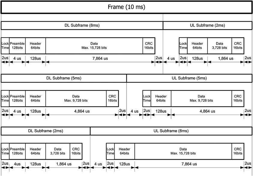
The frame structure for the FSDT scheme implemented using CDR is composed of a downlink sub-frame (or packet) and an uplink sub-frame (or packet), as shown in Figure 11 [29]. The length of a frame is 10 ms, and three sub-frame ratios are supported. The sub-frame ratios of the downlink versus the uplink are 8:2, 5:5, and 2:8. A downlink sub-frame consists of a lock time of 2 μs, a preamble of 128 bits, and a header of 64 bits. The data is shown in Figure 11. The dummy signal, which has a repeated pattern of 0 and 1 with the highest chip rate of 32 M chip per second during 2 μs, is used for the lock time. The dummy signal is used to give a CDR circuit an approximate reference frequency so that it reduces the time to align the phase to within 2 μs. An uplink sub-frame consists of a lock time of 2 μs, a header of 64 bits, and the data. There is a guard time of 2 μs for every sub-frame, which is the transition time between a receive mode and a transmit mode. From 250 kbps to 2 Mbps, four variable data rates are provided.
5 Analog Front-End for Human Body Communication
The analog front-end in Figure 10 is required to receive a data signal transmitted through the human body and recover the transmitted data signal. This section presents an analog front-end for HBC [11] with a simple structure and which is compatible with the HBC modem of earlier work [8].
5.1 Received Signal
Design of the analog front-end requires analysis of the signal propagation through the human body. The channel model presented in the previous section is usable for performance analysis, but not suitable for design of an analog front-end because performances of an analog front-end, such as a cut-off frequency of a filter or hysteresis of a comparator, cannot be accurately modeled in simulation using the channel model. As a result, designing an analog front-end based on signal measurement is more practical. The size of the ground plane affects the signal loss in the channel. A larger ground plane enhances the electric coupling such that the size of the ground plane for the receiver is determined depending on the application, e.g., a mobile phone. In this experiment, the receiver electrode was designed with an electrode size of 5 mm × 5 mm considering typical button size of a handheld phone, and a ground plane of 50 mm × 100 mm, which is a typical phone size. Adopting a single electrode is more user-friendly than employing two electrodes for the signal and the ground. A transmitter was located on one hand and powered using a USB cable by a battery-operated mobile terminal, i.e., an ultra-mobile PC. A transmitted signal generated by a field-programmable gate array (FPGA) passed through the human body and was transferred to the receiver electrode located on the other hand. The transmitted signal consisted of a dummy pattern of 2 μs and a Manchester-coded preamble of 4 μs. The dummy signal had a repeated pattern of 0 and 1 with a 32 M chip rate during 2 μs and hence provided the clock and data recovery (CDR) circuit an approximate reference frequency to reduce the time to align the phase within 2 μs. The Manchester-coded preamble had a 4 μs length with 128 bits.
The transmission distance was approximately 150 cm. The receiver electrode was connected to the active probe to maximize the isolation between the receiver and the earth ground. The measurement setup and measured signal, which has a strong low frequency mainly around 50 kHz for 110 ![]() , are shown in Figure 12. Figure 12 also shows a zoomed-in graph of Point A, which is the start point of a packet.
, are shown in Figure 12. Figure 12 also shows a zoomed-in graph of Point A, which is the start point of a packet.

The measured signal was band-pass filtered by combining a high-pass filter (cut-off frequency of 8 MHz) and a low-pass filter (cut-off frequency of 30 MHz) using the mathematical function of an oscilloscope. The band-passed signal had an amplitude of about 10 ![]() .
.
5.2 Design of an Analog Front-End
An analog front-end is designed based on the received signal measured on the human body. The signal loss in the channel (![]() ) is expressed in dB. It can be calculated as follows:
) is expressed in dB. It can be calculated as follows:
(7)
Here, ![]() is the received voltage and
is the received voltage and ![]() is the output voltage of the transmitter. If the output voltage of the transmitter is 3.3
is the output voltage of the transmitter. If the output voltage of the transmitter is 3.3 ![]() and there is signal loss of approximately 60 dB through the human body [27,30], the receiver must have sensitivity of at least 3.3
and there is signal loss of approximately 60 dB through the human body [27,30], the receiver must have sensitivity of at least 3.3 ![]() . As introduced in [28], the receiver separates the desired signal from all other signals induced on the channel, amplifies it to a level suitable for further processing, and determines its binary state using a comparator. A CDR circuit can be used to align the binary data to the clock. Figure 13 shows a block diagram of the analog front-end.
. As introduced in [28], the receiver separates the desired signal from all other signals induced on the channel, amplifies it to a level suitable for further processing, and determines its binary state using a comparator. A CDR circuit can be used to align the binary data to the clock. Figure 13 shows a block diagram of the analog front-end.

The first step is to define the gain of the amplifier. The gain of the receiver is determined based on the relationship between the minimum drive voltage of the comparator and the lowest amplitude of a signal that can be received. Figure 14 shows a simplified diagram of an HBC system that has a transmitter with a tri-state output buffer along with the channel (i.e., the human body) and a receiver front-end with an amplifier and comparator. High-pass filters implemented by passive and active components are omitted because they have little effect on the signal amplitude in the pass band. Because the human body is exposed to various electromagnetic environments, the received signal not only has strong low-frequency interference, but also high-frequency interference with relatively low amplitude. Positive feedback should be used to provide hysteresis and increase immunity to high-frequency noise. Maximum signal loss (![]() , dB), based on various body positions, of –70 dB [27] has been reported.
, dB), based on various body positions, of –70 dB [27] has been reported.

To define the amplifier gain (![]() ), the channel and amplifier are regarded as a single block, as depicted in the dotted box in Figure 14. The gain of the block is related to the output voltage of the transmitter (
), the channel and amplifier are regarded as a single block, as depicted in the dotted box in Figure 14. The gain of the block is related to the output voltage of the transmitter (![]() ) and the input drive voltage of the comparator (
) and the input drive voltage of the comparator (![]() ) as follows:
) as follows:
(8)
If the signal experiences a maximum path loss (![]() ) of –80 dB and the comparator can be driven by an input signal of 33
) of –80 dB and the comparator can be driven by an input signal of 33 ![]() , the amplifier should have a gain (
, the amplifier should have a gain (![]() ) of 40 dB. The receiver has a sensitivity of 330
) of 40 dB. The receiver has a sensitivity of 330 ![]() . The maximum signal loss, taken into account considering various body positions, is –70 dB [15], with loss variation of –5 dB and a receiver margin of –5 dB.
. The maximum signal loss, taken into account considering various body positions, is –70 dB [15], with loss variation of –5 dB and a receiver margin of –5 dB.
The next step is to define the active filter specifications (Figure 13). A Bessel filter with a maximally flat group delay is used as it preserves the wave shape in the pass-band. Because the spread baseband in the FSDT scheme is directly transmitted through a human body, its spectrum occupies a broad band. In order to find the characteristics of the filter type, a transient analysis was performed based on the measured data using the Agilent Advanced Design System. Based on the simulation, a fourth-order active high-pass filter was designed with an 8 MHz cut-off frequency. The utilization of hysteresis on the comparator, together with the 200 MHz gain bandwidth product of the operational amplifier IC, can remove the high-frequency noise in the received signal, thus allowing use of a high-pass filter instead of a band-pass filter that was used in previously described experiments.
The induced noise of the 50 Hz or 60 Hz alternating current, caused by electric power transmission and fluorescent lighting, could be tens of volts on the human body. This noise is likely to saturate the active circuits with the supply voltage of 3.3 V used in the analog front-end and thus should be reduced to a point as low as the signal as the receiver can accommodate without saturation. A passive second-order high-pass filter realized using a series capacitor and two resistors connected between the supply voltage and ground offers half of the supply voltage, which provides the maximum swing range of the received signal without saturation. Figure 15 shows a simulated signal from the electrode to the comparator based on measured data. The processed signal has 4.6 ns of root-mean-square (RMS) eye jitter. This originates from noise, the induced interference, inter-symbol interference, and a band-limited channel during signal transmission, and from the physical limitations of the slew rate of the circuit and the hysteresis of the comparator. The received signal is strongly amplified, filtered, and then switched rapidly between two levels, at which point the data are finally recovered from the processed signal with jitter using a CDR circuit. A transmitted signal consisting of a spread signal using a group of Walsh codes and a Manchester-coded preamble is represented by a unipolar non-return-to-zero (NRZ) level with 0 and 3.3 V and with only two consecutive identical chips. This enables the proposed scheme to be used in asynchronous communication. The timing information is extracted and the chip stream regenerated using a CDR circuit from the received data while receiving a signal within a 2-chip delay. A voltage-controlled oscillator (VCO) is a type of oscillator whose oscillator frequency is controlled by a voltage input. The applied input voltage, named as a control voltage (![]() ), determines the instantaneous oscillation frequency. The CDR is used as a local oscillator during transmission to generate a nominal frequency or a center frequency of a VCO by setting the control voltage (
), determines the instantaneous oscillation frequency. The CDR is used as a local oscillator during transmission to generate a nominal frequency or a center frequency of a VCO by setting the control voltage (![]() ) to a specific level, generally at the center of the supply voltage (
) to a specific level, generally at the center of the supply voltage (![]() in Figure 13). Within a frame, the master and slave should exchange data once with each other. This technique can periodically initialize a frequency offset between the clocks of the master and slave within a few ppm and prevent clock frequency drift. In HBC, data transfers cannot be deliberately started and stopped and thus a fast lock time is needed. The traditional frequency lock time of the phase lock loop used in a CDR is generally a few hundreds of microseconds. The slave operates as a receiver during a downlink and as a transmitter during an uplink time slot. In order to track the transmitted signal as receiving data at the downlink time slot, the output voltage of the loop filter (Vloop) is used as the control voltage (VC) of VCXO by RXE in Figure 13. When no data is received at the downlink as well as at the uplink, the external voltage (Vext) is used as VC to use CDR as a local oscillator. The clocks of the master and slave only exhibit a phase difference within a limited time, i.e., a frame length without buffer memory. In addition, dummy patterns of 2 μs composed of periodic data at 32 Mcps are used for training the CDR. The dummy pattern and oscillation mode during transmission can settle the control voltage to within 2 μs.
in Figure 13). Within a frame, the master and slave should exchange data once with each other. This technique can periodically initialize a frequency offset between the clocks of the master and slave within a few ppm and prevent clock frequency drift. In HBC, data transfers cannot be deliberately started and stopped and thus a fast lock time is needed. The traditional frequency lock time of the phase lock loop used in a CDR is generally a few hundreds of microseconds. The slave operates as a receiver during a downlink and as a transmitter during an uplink time slot. In order to track the transmitted signal as receiving data at the downlink time slot, the output voltage of the loop filter (Vloop) is used as the control voltage (VC) of VCXO by RXE in Figure 13. When no data is received at the downlink as well as at the uplink, the external voltage (Vext) is used as VC to use CDR as a local oscillator. The clocks of the master and slave only exhibit a phase difference within a limited time, i.e., a frame length without buffer memory. In addition, dummy patterns of 2 μs composed of periodic data at 32 Mcps are used for training the CDR. The dummy pattern and oscillation mode during transmission can settle the control voltage to within 2 μs.

5.3 Operation of CDR
The receiver implemented using CDR has the advantage of higher data throughput performance compared to the scheme using pilot signal. The information in the frame can be used to control the CDR in order to synchronize between the HBC devices as well as to reduce the power consumption. Figure 16(a) shows the control signals related to the sub-frame ratio and the length of the received data. A control signal denoted as Rx_valid expresses the sub-frame ratio of the downlink versus the uplink and is set to a “logic high” setting during the downlink. A signal denoted as RXE expresses the length of the received data. When a master transmits data, a slave starts to receive the data, after it has passed through the human body. This point is marked as ![]() in Figure 16(a). The CDR of the slave in the receiving mode locks in the phase and frequency to the received signal that is represented as unipolar NRZ with the clock information of the transmitter. The control voltage of VCXO varies according to the frequency of the received signal, which is nearly identical to the frequency of the transmitter. This is the period marked as
in Figure 16(a). The CDR of the slave in the receiving mode locks in the phase and frequency to the received signal that is represented as unipolar NRZ with the clock information of the transmitter. The control voltage of VCXO varies according to the frequency of the received signal, which is nearly identical to the frequency of the transmitter. This is the period marked as ![]() in Figure 16(a). If the received data is less than the allowable maximum size, the Rx data ends before the end of Rx_valid, as shown in Figure 16(a). This point is marked as
in Figure 16(a). If the received data is less than the allowable maximum size, the Rx data ends before the end of Rx_valid, as shown in Figure 16(a). This point is marked as ![]() in Figure 16(a). In general, at the end of the received data, a lack of level transitions in the received signal for a considerable number of clock cycles should be noted. As long as the received signal is not present, the CDR is kept idle by the loss-of-signal (LOS) control signal, which is generated by the input stage of the CDR. Most CDRs have a function that sets the control voltage of VCXO under the LOS condition. The CDR used for the FSDT scheme has a LOSIN terminal to control the control voltage. The LOS output signal is normally “logic low” and is set to “logic high” after 256 consecutive clock periods with no transition of the received signal. The LOS signal can be used to either flag external alarm circuits and/or drive the CDR’s LOSIN input. When LOSIN is set to “logic high,” the VCXO control voltage is switched to an internal voltage, usually half of the supply voltage, to generate a nominal frequency. The LOS signal is reset to “logic low” as soon as there are received signal transitions.
in Figure 16(a). In general, at the end of the received data, a lack of level transitions in the received signal for a considerable number of clock cycles should be noted. As long as the received signal is not present, the CDR is kept idle by the loss-of-signal (LOS) control signal, which is generated by the input stage of the CDR. Most CDRs have a function that sets the control voltage of VCXO under the LOS condition. The CDR used for the FSDT scheme has a LOSIN terminal to control the control voltage. The LOS output signal is normally “logic low” and is set to “logic high” after 256 consecutive clock periods with no transition of the received signal. The LOS signal can be used to either flag external alarm circuits and/or drive the CDR’s LOSIN input. When LOSIN is set to “logic high,” the VCXO control voltage is switched to an internal voltage, usually half of the supply voltage, to generate a nominal frequency. The LOS signal is reset to “logic low” as soon as there are received signal transitions.

In HBC, however, random noise received from the human body is processed with the receiver chain, finally becoming binary digital data with an arbitrary pulse width. As a result, between the end of the received data and the end of the sub-frame of the downlink or the start of the sub-frame of the uplink (marked as ![]() in Figure 16(a)), the phase of the incoming signal has a random difference from the phase of the local oscillator of the CDR. The processed random noise causes the CDR to lose its lock.
in Figure 16(a)), the phase of the incoming signal has a random difference from the phase of the local oscillator of the CDR. The processed random noise causes the CDR to lose its lock.
When the slave transmits the data marked as ![]() in Figure 16(a), the transmitted signal leaks to the receive path of the slave. The feedback loop is formed: i) the CDR provides the clock frequency of the transmitted signal; ii) the transmitted signal leaks through an electrode to the receive path; iii) the leakage signal of the transmitted signal is processed and a comparator makes it a binary waveform with the frequency of the transmitter; iv) this signal is then connected to the CDR; and v) finally, the feedback loop is formed and the control voltage of VCXO converges to a constant value, generally half of the supply voltage, which generates the nominal frequency of VCXO. The same problem occurs when the transmitted signal is less than the allowable maximum period, marked as
in Figure 16(a), the transmitted signal leaks to the receive path of the slave. The feedback loop is formed: i) the CDR provides the clock frequency of the transmitted signal; ii) the transmitted signal leaks through an electrode to the receive path; iii) the leakage signal of the transmitted signal is processed and a comparator makes it a binary waveform with the frequency of the transmitter; iv) this signal is then connected to the CDR; and v) finally, the feedback loop is formed and the control voltage of VCXO converges to a constant value, generally half of the supply voltage, which generates the nominal frequency of VCXO. The same problem occurs when the transmitted signal is less than the allowable maximum period, marked as ![]() in Figure 16(a).
in Figure 16(a).
In HBC, the user rapidly establishes connections to networks by touching the devices. A fast lock-in time of CDR is essential to characterize HBC in comparison with general wireless communication. In order to reduce the lock-in time, the frequencies of the master and the slave should be synchronized or maintained at a nominal frequency, after which the acquisition of the phase lock and the tracking of the acquired phase timing are processed. A simple solution to synchronize or maintain the frequencies of the master and the slave is to maximize the size of the data for all sub-frames. This can be accomplished by adding a dummy signal to the transmitted data for both the master and the slave. The dummy signal has a waveform with the repeated pattern of 0 and 1, with the highest chip rate, as used in the lock time. By adding the dummy signal, there is no period without transitions of the received signal even when the size of the data is less than the maximum value. As a result, no random binary signal induced on the human body is injected into the CDR. However, this method consumes additional power due to the extra pattern.
Another approach is to manage the control voltage of VCXO, as shown at the bottom of Figure 16(b). The signal of RXE depicted in Figure 16 (b) is set to “logic high” while in the presence of received data, and the signal of RXE is the complementary signal of RXE. The RXE signal is a control signal that is used to switch the control voltage of VCXO between the output of the loop filter and the external voltage. While in the presence of received data, VCXO is controlled by the output voltage of the loop filter. The control voltage of VCXO is set to the external voltage throughout all periods of the frame except in the presence of the received signal. The external voltage is generally half of the supply to generate the nominal frequency, as shown in the middle of Figure 16(b). In addition, the signal of RXE or RXE can serve as a control signal to enable or disable a comparator. According to the polarity at which the comparator needs to be enabled, one of the two signals is used. If the comparator is shut down, a CDR that is positioned after the comparator receives no transition of the signal, as shown in Figure 15. The operation of the comparator by RXE is shown in Figure 16(b). As a result, the output signal, denoted as the CDR input in Figure 16(b), intuitively describes the condition of a loss-of-signal (LOS) for the CDR. Under the LOS condition, the control voltage of VCXO in the CDR generates the nominal frequency and the CDR then becomes ready to play the role of the local oscillator during the transmitting period.
6 Performance of the Analog Front-End
The performance of the analog front-end using the FSDT scheme is summarized in Table 2 [11]. The transceiver for the FSDT scheme has high sensitivity of –78 dBm and a wide dynamic range of 82 dB. The FSDT transceiver does not need complex circuitry such as analog blocks for a transmitter, a switch circuit for duplexing, a mixer for frequency translation, a low-pass filter for reducing high-frequency noise, and an ADC with a fast sampling frequency. It can reduce the power consumption as well as the degree of circuit complexity. Although the transceiver offers these advantages and thus can be implemented using off-the-shelf components, much power is dissipated.
Table 2
Performance Summary of the Various Analog Front-ends for HBC
| Technology | FSDT ‘12 [11] | FSK ’09 [7] | Wideband Digital Transmission ’09 [27] |
| Frequency Band | 8~22 MHz | 30~120 MHz | 1~30 MHz |
| Modulation | No | FSK | No |
| Interference Rejection Technique | Frequency selective Walsh spread | Adaptive Frequency Hopping | Input clamping |
| Data Rate | 2 Mbps | 10 Mbps | 8.5 Mbps |
| Sensitivity | 250 |
503 |
350 |
| Dynamic Range | >82 dB | NA | NA |
| BER | <10−6 @ 250 |
<10−5 @ 710 |
<10−3 @ 450 |
| Power Consumption | 194.7 mW | 4.6 mW | 2.75 mW |

The FSDT scheme also provides lower data rates compared to two earlier examples [7,27]. The data rate can be improved by modifying the spreading scheme while maintaining the structure of the analog front-end. If the transmission scheme uses a half-length of the Walsh code, which has a spreading factor that is twice as great, it will have the same chip rate at the output of the transmitter. Hence, it is not necessary to modify any circuit in the analog front-end. Theoretically, the data rate is doubled and the signal-to-noise ratio is degraded by 3 dB. As shown in Table 2, the analog front-end using the FSDT scheme provides better BER performance at a low input power. The FSDT scheme can thus improve the data rate and maintain the target BER while reducing the processing gain in the spread spectrum signal.
7 Commercialization of Human Body Communication and its Challenges
For the commercialization of HBC, various transmission techniques and application models have been developed, and HBC standardization progressed simultaneously. In comparison with general wireless communication for health-monitoring sensors, for which a frequency of several hundreds of MHz (e.g., the Medical Implant Communication Service (MICS) band [5]) is typically used, HBC uses a very low frequency of less than 100 MHz, as the human body as a transmission medium supports signal transmission in a low-frequency band. This feature gives HBC a performance-related advantage: supporting high-data-rate transmission while maintaining a low level of power consumption. As HBC uses a low frequency for signal transmission, propagation delay does not occur significantly during transmission [26]; therefore, the data rate can be increased without compensation for the propagation delay. It has been presented that HBC can support a high data rate of up to 10 Mbps [29,31,32]. Also, a baseband-transmission technique [5,8–11], in which a baseband signal is transmitted through the human body without analog modulation to transform the baseband signal into a passband signal, has been proposed for HBC, allowing the power consumption of the modem and the analog front-end to be reduced. Due to the low power consumption, HBC has been applied to data communication for a capsule-type endoscope [33], in which it captures high-quality images of the inside of the bowel and transmits the captured images to a receiver on the surface of the body using HBC. Several companies have released a prototype module or a system solution using HBC [34–36]. The prototype modules and system solutions can be applied to various types of data transmission, including transmission of the identification information, but a healthcare service using wearable sensors has been also considered as one of the major applications of the modules and solutions. At the IEEE 802.15 working group, HBC PHY using the FSDT scheme has been adopted as a standard for short-range communication on the surface of the human body [5]. In addition, an interface for HBC is being standardized by the IEC TC47 standard committee [37]. The interface standard defines the electrode specifications, including the size and materials, as well as the operating conditions required to secure normal operation of the interface.
Several challenges, however, remain before the usefulness of HBC can be improved and, consequently, its potential for wearable sensors can be realized. The channel model in earlier research [21] can be applied only to signal transmission between on-body sensors, but it should be extended to signal transmission between on-body and in-body sensors, or between in-body sensors only. To do this, a modeling technique to model the human body, which is composed of various tissues, and a measurement technique to measure the channel properties inside the human body, should be studied. HBC PHY in [5] supports only a single transmission channel and cannot therefore be applied to communication between a hub and multiple nodes in a sensor network. For HBC to support multi-node communication, a multichannel technique should be introduced along with an avoidance technique to deal with adjacent channel interference.