Wearable Haptics
Yuichi Kurita, Institute of Engineering, Hiroshima University, Hiroshima, Japan
Haptic display represents a promising interface for human-computer interaction that provides users with nuanced information in virtual environments. Humans utilize tactile and haptic information to determine object properties using thousands of mechanoreceptors located in the hands. Various haptic illusions can also be created by applying vibration and/or deformation to tactile mechanoreceptors. This chapter describes the state-of-the-art in wearable haptic display devices. Improving haptic and tactile sensory capability may help to enhance motor performance. Such devices could assist workers engaged in tasks requiring high-precision manual dexterity. Two research studies are addressed in detail. The first study aims to explore the challenge of displaying a friction and weight illusion based on fingertip deformation, whereas the second study describes a wearable sensorimotor enhancer that improves tactile sensitivity in human fingertips.
Keywords
Haptic display; haptics; sensorimotor enhancer; stochastic resonance; tactile display; tactile sensor; wearable systems; weight and friction illusion
1 Introduction
The field of haptics has grown in recent decades, and haptic display is now viewed as a highly promising approach to interfaces in human-computer interaction because it provides users with nuanced information in virtual environments. In applications ranging from physical rehabilitation to tele-operation of remote robotic systems, haptic feedback can provide intuitive and valuable information, thereby facilitating the user’s understanding of force and motion.
The word haptic comes from the Greek word haptikos, which relates to the sense of touch – also known as the tactile sense [1]. Humans rely on the sense of touch in real environments. This sense allows us to understand the nature of objects. We also use haptic information to hold objects and manipulate them. The goal of a haptic feedback system is to help users feel physical characteristics, interact with virtual or distant environments, and intuitively manipulate remote objects.
Humans utilize tactile and haptic information to determine object properties using thousands of mechanoreceptors located in the hands [2]. Researchers have determined that different mechanoreceptors work collectively to provide different cutaneous sensations [3]. Various haptic illusions can be created by applying vibration and/or deformation to tactile mechanoreceptors, which exhibit either rapidly adapting (RA) or slowly adapting (SA) response characteristics. RA and SA receptors each have two sub-classes: RA I (Meissner corpuscles) and RA II (Pacinian corpuscles), and SA I (Merkel cells) and SA II (Ruffini endings). These four major mechanoreceptors provide information for detecting touch, pressure, frequency, slip, and the texture of objects.
2 The Need for Wearable Haptic Devices
Tactile and haptic information is essential for completing tasks and control operations. Haptic feedback systems can be classified into three types according to their mechanical grounding configuration [4]: the grounded type, the non-grounded type, and the wearable type. Grounded haptic devices readily provide information on weight sensation and three-dimensional forces. PHANToM is one of the most widely used commercially available haptic devices [5]. It has a serial link mechanism with a counterbalance weight and a back-drivable arm, and can exert forces along multiple axes and torques at the device’s pen tip. Sato et al. developed a series of wire-driven haptic devices (the SPIDAR series) [6–8] such as SPIDAR-G, which has seven degrees of freedom (DOF) for force feedback: three for translation, three for rotation, and one for grasping. The device provides smooth force feedback with minimal inertia, no backlash, and superior levels of scalability and safety. Arata et al. developed a haptic device that can exert three-axis force control (DELTA-4) [9]. Its parallel link mechanism contributes to the high rigidity of the device. In the robotics field, various haptic feedback methods have been developed for a tele-operation system [10–13]. These devices provide powerful haptic feedback with a simplified design. Their weight is of little significance because they are usually fixed to a static object or to the ground. However, haptic interaction with virtual environments is limited to small workspaces. Non-grounded haptic devices employ a counteractive mechanism that creates linear or angular momentum [14–16] and does not require ground connection, thus allowing for the device to be mobile or wearable. However, such devices cannot generate large forces. Exerting force in multiple directions and maintaining continuous intensity are also problematic.
Wearable haptic devices allow for greater freedom and a larger workspace than grounded systems. As the computing environment moves from desktop to mobile platforms, new computer interfaces and human-computer interaction tools for mobile systems are required. Wearable sensor systems have been developed to allow monitoring of people anywhere and at any time [17–19] and wearable haptics can be utilized as a part of the feedback mechanism. Because tactile stimulation can be perceived through the skin all over the body, utilizing the sense of touch is key in maximizing attentional resources [20]. A device that can be strapped to the user is desirable for the provision of more intuitive sensation because placement near the user’s skin and/or joints enables more direct haptic feedback.
Technologies used in the development of wearable haptic and tactile display are divided into three categories: force feedback, vibro-tactile feedback, and electronic feedback. Force feedback provides stimuli for the kinematic sense. Vibro-tactile feedback is aimed more at the tactile senses. Electronic feedback leverages the electrical conductivity of human skin to evoke tactile sensations.
3 Categories of Wearable Haptic and Tactile Display
3.1 Force Feedback Devices
There are two types of haptic feedback systems with force feedback capability that can be considered as wearable devices: exoskeletons and fingertip-mounted devices. Exoskeletons allow users to manipulate virtual objects based on various types of haptic feedback. A glove-type exoskeleton is provided as a simple and practical design for fingers and hands.
The CyberGrasp [21] from Immersion Corporation is a commercially available exoskeleton system. It has four fingers and allows force feedback on different phalanxes with a cable-driven exoskeleton structure attached to the back of the user’s hand. SPIDAR-8 [22] is a two-handed multi-finger haptic interface device. It has eight fingertip attachment devices connected with strings to enable calculation of the 3D position of each fingertip. Haptic force is displayed by controlling the tension of the strings. HapticGEAR also employs a wire tension mechanism to display force, but the user feels force via the tip of a pen-type grip with a backpack-type mechanism to minimize fatigue for the wearer [23]. The Rutgers Master II [24] is a light and compact system composed of four small air cylinders placed inside the palm and attached to the fingertips. Its configuration does not depend on finger size, and its calibration is simplified. The telexistence cockpit system [25] represents the force of gravity by displaying multi-DOF haptic force at the operator’s wrist. Yang et al. proposed a seven-DOF haptic device that can be worn on a human arm. Its operation involves the use of mechanical links/joints and human bones/joints [26]. Kobayashi et al. developed a two-fingered body-grounded haptic device called ExoPhalanx, which provides force to the distal segment of the human operator’s thumb and middle finger and to the basipodite of the middle finger [27]. They provide both tactile and visual feedback using servo motor actuators and tendons attached to each of the user’s fingers.
The primary problem with exoskeletons is the need for user-specific calibration. Considering the strength-mass and power-mass ratios of existing materials and actuators, fingertip devices are an interesting solution compared to exoskeletons [28]. A variety of fingertip-mounted devices have been developed for finger-based interaction [29–31]. For example, Gosselin et al. proposed a wearable haptic interface developed for precise finger interaction within virtual reality applications in large environments [32]. Aoki et al. developed a fingertip-mounted haptic device to provide contact for cutaneous sensation using wires for mixed-reality environments [33]. Minamizawa et al. integrated an underactuated mechanism with one-point kinesthetic feedback from the arm with multipoint tactile feedback [34]. Kawasaki et al. developed a hand haptic interface for use in palpation training in virtual reality environments. The device consists of finger-pad force display devices and a 3D fingertip haptic display device [35]. Chinello et al. developed a small-scale lightweight wearable haptic display that allows fingertip stimulation with a wide range of contact forces [36]. Ando et al. developed a fingernail-mountable tactile display that allows the user to feel various textures when touching smooth objects [37].
The complexity, size, and weight of fingertip-mounted devices is lower than that of exoskeletons, but they still allow most interactions including kinematic and tactile senses. However, only precision grasping can be efficiently simulated because no force is fed back to the phalanxes.
3.2 Vibro-Tactile Feedback Devices
Vibration is widely used as a haptic technology for cutaneous feedback to stimulate the tactile senses. Haptic display based on vibro-tactile feedback is easy to implement and provides robust sensation. Such feedback is a useful tool for guiding users with limited visual cues. Konyo et al. proposed a wearable stimulation device that can produce various distributed stimuli on human skin in response to hand movements using ICPF (Ionic Conducting Polymer gel Film) actuators [38]. Kevin et al. developed a wearable wireless haptic piano instruction system composed of five small vibration motors (one for each finger) inside a glove [39]. Kapur et al. developed a rehabilitation system that employs vibro-tactile feedback for stroke victims [40]. Phong and Chellali proposed two forms of vibro-tactile information known as continuous and frequency-modulation-based vibrotactile (FMBV) feedback [41]. Garcia-Hernandez et al. evaluated subjects’ tactile ability to discriminate small virtual ridge patterns using a portable-wearable tactile device [42]. Ding et al. developed the wearable InterfaceSuit, which enables human motion replication and learning in co-space, and also proposed a human-to-human motion replication methodology with multi-modal feedback mechanisms [43].
The use of vibro-tactile feedback has expanded to many different applications. Haptic illusion displays have been developed in consideration of vibration sensitivity differences by applying carefully designed vibration patterns to cutaneous mechanoreceptors [44–46]. However, tactile sensation of motion from vibrating motors can be masked by kinesthetic movement of the human body in mobile conditions [47].
3.3 Electro-Tactile Feedback Devices
Electro-tactile stimulation evokes tactile sensation on the skin by passing a current through surface electrodes. Although electro-tactile display requires direct contact between the skin and the surface electrode, small flexible electrodes are now commercially available.
Kajimoto et al. developed various electro-tactile display approaches, including a haptic interface with electrotactile-kinesthetic integration for dexterous manipulation [48], an electro-tactile display with a repeated electrode structure for enlarged display [49], and an electro-tactile display with real-time impedance feedback using pulse width modulation [50]. Lee and Starner proposed a design for wearable textile-based electro-tactile display in a wristband that can be integrated with current mobile phones and wearable computers [51]. Tamaki et al. developed PossessedHand, which controls the user’s fingers by applying electrical stimulus to the muscles around the forearm [52].
The sensation delivered through surface electrodes sometimes causes pain to users. In this context, controlling sensation to a comfortable level is challenging in the design of electro-tactile displays [53].
4 Display of Friction and Weight Illusions Based on Fingertip Manipulation
4.1 Creation of Haptic Sensation via Finger Pulp Manipulation
Other studies have investigated the creation of haptic sensation based on finger pulp manipulation to stimulate cutaneous mechanoreceptors by producing slip/shear force on the skin. Lee et al. developed a type of display that pushes pins up to apply pressure to the user’s fingertips [54]. The device was found to be capable of forming shapes and patterns for subjects to identify. Webster et al. proposed a tactile haptic slip display involving the combination of a slip display with a force feedback haptic device [55]. Chen et al. developed a shear/slip feedback device that stimulates different texture sensations by rotating at various speeds [56]. Minamizawa et al. proposed a wearable ungrounded haptic display that creates realistic gravity sensation for virtual objects via fingerpad manipulation [57]. Yokota et al. produced the sensation of softness using an electrostatic device with a slider film that controls spacing between the user’s finger and the device [58]. Bark et al. developed a wearable haptic feedback device that imparts rotational stretch to hairy skin for motion display [59]. Tsukada and Yasumura developed a wearable interface called ActiveBelt that enables users to obtain multiple directional information via the tactile sense [60]. Damian et al. developed a wearable single-actuator haptic device that relays multi-modal haptic information on variables such as grip force and slip speed [61].
Although the skin stretch method is considered to generate more direct sensation than vibro- and electro-feedback because the skin is physically deformed, these devices can display relative haptic sensation (i.e., levels heavier/lighter or rougher/smoother than the default value) based on an ad hoc control strategy. A sophisticated control strategy is needed to display target object parameters such as weight and friction. Kurita et al. explored the challenge of displaying friction and weight illusions based on fingertip deformation [62] when lifting a weight with two fingers. The proposed device has three significant characteristics. The first is its wearability, which ensures that it occupies only a small space. Users pinch the device with the thumb and index finger. The device is fixed to the finger phalanges, and the contact area at the fingertip is manipulated via the sliding of a plate at the part where the user holds it. The second characteristic is the device’s absence of a force sensor in favor of a small built-in camera that allows estimation of manipulation at the fingertip by visualizing the contact area between a transparent plate and the fingertip (Figure 1).
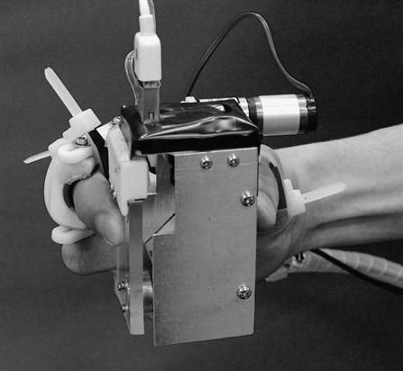
The third characteristic is the device’s capability to display arbitrary weight and friction values using eccentricity control. Eccentricity is used as a quantitative index of deformation at the contact area. Its mathematical relationship with skin deformation can be determined based on known material parameters, normal and tangential forces applied to the contact area, and the friction coefficient [63].
4.2 Deformation of the Contact Area
Contact between an elastic sphere and a rigid plate is called Hertzian contact. Figure 2 shows a schematic image of the contact occurring when a normal (vertical) force ![]() and a tangential (lateral) force
and a tangential (lateral) force ![]() are applied. Here, relative displacement (i.e.,
are applied. Here, relative displacement (i.e., ![]() in Figure 2) occurs due to the deformation of the elastic object. The analytic solution of
in Figure 2) occurs due to the deformation of the elastic object. The analytic solution of ![]() is given by:
is given by:
(1)
 (1)
(1)
where the radius of the contact area ![]() R is the radius of the elastic object,
R is the radius of the elastic object, ![]() is the friction coefficient of the contact area, and
is the friction coefficient of the contact area, and ![]() are the equivalent Young’s modulus and Poisson’s ratio of the elastic object.
are the equivalent Young’s modulus and Poisson’s ratio of the elastic object.
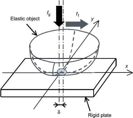
Variables ![]() and
and ![]() correspond to the weight of the object and the static friction of the contact surface when the object is held. This implies that haptic illusions in weight and friction sensation can be created by applying the appropriate relative displacement
correspond to the weight of the object and the static friction of the contact surface when the object is held. This implies that haptic illusions in weight and friction sensation can be created by applying the appropriate relative displacement ![]() , which can be determined by calculating the distance between the contact center at the default position and that observed when the fingertip is deformed. However, it is difficult to measure relative displacement precisely with a low-resolution camera because displacement relating to fingertip deformation is very small. In this study, eccentricity [63,64] was used as an index of elastic object deformation. It is easier to determine eccentricity than to directly measure displacement because its calculation is based on the contact area between an elastic object and a rigid plate.
, which can be determined by calculating the distance between the contact center at the default position and that observed when the fingertip is deformed. However, it is difficult to measure relative displacement precisely with a low-resolution camera because displacement relating to fingertip deformation is very small. In this study, eccentricity [63,64] was used as an index of elastic object deformation. It is easier to determine eccentricity than to directly measure displacement because its calculation is based on the contact area between an elastic object and a rigid plate.
The contact area can be separated into four parts as shown in Figure 3 based on its center. The deformation of this area along the ![]() axis
axis ![]() is calculated as follows:
is calculated as follows:
(2)
where ![]() and
and ![]() represent the respective areas of each part. The eccentricity
represent the respective areas of each part. The eccentricity ![]() along the
along the ![]() axis is defined as follows:
axis is defined as follows:
(3)
where ![]() and
and ![]() represent the whole contact area, and
represent the whole contact area, and ![]() and
and ![]() are calculated for the neutral position and that after the application of traction force, respectively. Eccentricity is a dimensionless value normalized by the contact area.
are calculated for the neutral position and that after the application of traction force, respectively. Eccentricity is a dimensionless value normalized by the contact area.

When ![]() , the following approximation is obtained:
, the following approximation is obtained:
(4)
Eccentricity along the y axis is calculated by substituting Eq. (1) into Eq. (4):
(5)
 (5)
(5)
(6)
When an object is lifted up, ![]() and
and ![]() correspond to its weight and friction. This implies that weight and friction sensation can be represented by measuring and controlling
correspond to its weight and friction. This implies that weight and friction sensation can be represented by measuring and controlling ![]() rather than
rather than ![]() . Figure 4 shows the eccentricity calculated using Eq. (6) when the object weight changes from 50 to 500 g in (a), and the friction changes from 0.4 to 1.8 in (b). The influence of weight on eccentricity is relatively large; the difference is observed at the beginning (t<0.1). The influence of friction is smaller than that of weight; the difference appears late (around t=0.3) and becomes larger as the friction coefficient decreases.
. Figure 4 shows the eccentricity calculated using Eq. (6) when the object weight changes from 50 to 500 g in (a), and the friction changes from 0.4 to 1.8 in (b). The influence of weight on eccentricity is relatively large; the difference is observed at the beginning (t<0.1). The influence of friction is smaller than that of weight; the difference appears late (around t=0.3) and becomes larger as the friction coefficient decreases.

4.3 Weight and Friction Illusion Display
A prototype display device was developed to produce haptic illusions of weight and friction via eccentricity control for the contact surface of a human fingertip. The device consists of a transparent acrylic plate, a motor to actuate the plate, and a camera to capture images of the contact surface.
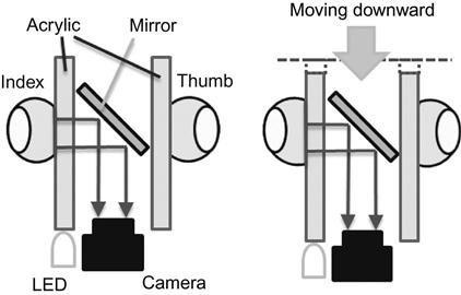
An overview of the device and a schematic image of its operating principle are shown in Figure 1 and Figure 5. The total weight of the device is 210 g. The user inserts the thumb and index finger into the rings attached to the device and pinches it so that the index finger is on the center of the transparent plate. Here, the user’s hand was fixed to the body of the device at the middle phalanx of the thumb and at the middle and proximal phalanges of the index finger using plastic belts. The camera captures images of the contact surface at 60 fps. Here, morphological image processing for opening and smoothing was applied to the images captured, and binarized contact images as shown in Figure 6 were obtained. The contours of the contact images were used to calculate eccentricity.

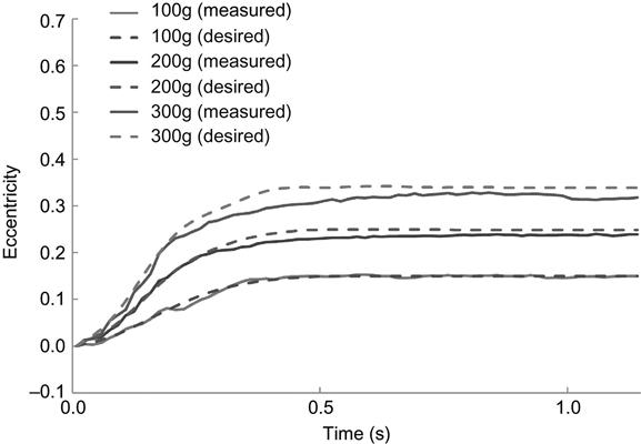
The actuator controls motor torque to achieve the desired eccentricity. As shown in Figure 7, the desired and measured eccentricity with the target weight and friction were set as ![]() , and
, and ![]() . Highly favorable eccentricity display performance was confirmed.
. Highly favorable eccentricity display performance was confirmed.
The efficacy and usefulness of the prototype were investigated in three evaluation experiments involving weight display and friction display with 10 healthy subjects aged from 22 to 24 years old. The weight-friction illusion device was attached to the dominant hand of the subjects, who were instructed to place the same hand on a table and to relax their torso and non-dominant hand. They were then asked to lift the device to a height of 200 mm in 2 seconds. Eccentricity feedback control was started when the device left the table. After lifting and deposition were complete, the experimenter detached the device from the subject’s hand. The subjects were then asked to lift a test object up and down freely.
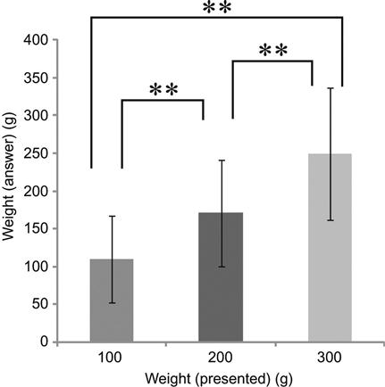
In the weight display test, the displayed weights were ![]() , and 300 g. When the target weight is heavier than the weight of the device itself, the actuator moves the plate downward where the subjects pinched; when the target weight is lighter than the device, the actuator moves the plate upward. The texture of the contact surface between the display device and the fingertip was fixed using oil to have a value of approximately
, and 300 g. When the target weight is heavier than the weight of the device itself, the actuator moves the plate downward where the subjects pinched; when the target weight is lighter than the device, the actuator moves the plate upward. The texture of the contact surface between the display device and the fingertip was fixed using oil to have a value of approximately ![]() . The subjects could change the weight of the test object to 50, 100, 150, 200, 250, 300, 350, and 400g by placing weights on the test object container. The surface texture of the test object was the same as that of the display device. The subjects were asked to select the one they judged to have the same weight as the displayed value. In the friction display test, the displayed friction values were μ=0.6, 0.9, and 1.2. The weight of the display device was fixed at 200 g. The weight of the test object was the same as that of the display device. The subjects could change the friction coefficient of the test object to approximately μ=0.4, 0.6, 0.9, 1.2, and 1.7 by replacing the contact plate. The subjects were asked to select the one they judged to have the same friction as the displayed value. Figure 8 and Figure 9 show the subjects’ answers in the weight and friction display test, respectively. The results of the experiments indicate that the prototype successfully displayed weight and friction illusions to the subjects. However, gaps were also observed between the target sensations displayed by the device and the subjective sensations actually felt by the subjects. Measurement of forces during the task and utilization of data to modulate the desired eccentricity are expected to improve the range of weight and friction values that can be presented to users using more sophisticated models and devices.
. The subjects could change the weight of the test object to 50, 100, 150, 200, 250, 300, 350, and 400g by placing weights on the test object container. The surface texture of the test object was the same as that of the display device. The subjects were asked to select the one they judged to have the same weight as the displayed value. In the friction display test, the displayed friction values were μ=0.6, 0.9, and 1.2. The weight of the display device was fixed at 200 g. The weight of the test object was the same as that of the display device. The subjects could change the friction coefficient of the test object to approximately μ=0.4, 0.6, 0.9, 1.2, and 1.7 by replacing the contact plate. The subjects were asked to select the one they judged to have the same friction as the displayed value. Figure 8 and Figure 9 show the subjects’ answers in the weight and friction display test, respectively. The results of the experiments indicate that the prototype successfully displayed weight and friction illusions to the subjects. However, gaps were also observed between the target sensations displayed by the device and the subjective sensations actually felt by the subjects. Measurement of forces during the task and utilization of data to modulate the desired eccentricity are expected to improve the range of weight and friction values that can be presented to users using more sophisticated models and devices.


5 A Wearable Sensorimotor Enhancer
5.1 Improvement of Haptic Sensory Capability for Enhanced Motor Performance
Improving haptic and tactile sensory capability helps to enhance motor performance. In this context, a fingertip-wearable device that improves motor performance could be used to assist workers engaged in tasks requiring high-precision manual dexterity. A variety of such devices have been developed in the past.
Mascaro and Asada developed a photoplethysmograph fingernail sensor that measures two-dimensional variations in blood volume beneath the fingernail for estimation of normal force, lateral shear force, longitudinal shear force and bending angle based on readings from the sensor [65]. Provancher and Sylvester revealed that the perceived magnitude of friction rendered by conventional force feedback can be increased with the addition of fingertip skin stretch [66]. Tanaka et al. developed a tactile device called a tactile nail chip that can be mounted on the fingernail and deforms it to change tactile perceptivity [67]. Jeong et al. reported that vibration sensitivity changes as a result of tangential vibration application to the skin surface [68]. Romano et al. developed the SlipGlove, which provides tactile cues associated with slippage between the glove and a contact surface [69].
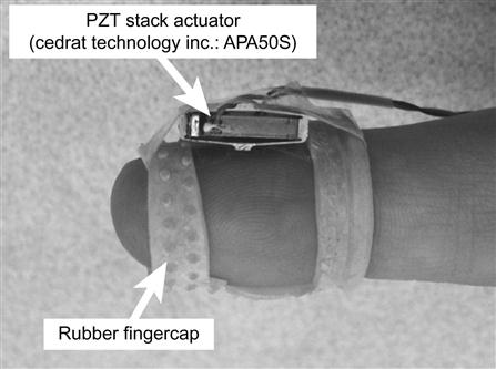
Some researchers have also reported that Stochastic Resonance (SR) improves tactile and haptic sensitivity in the feet, hands, and fingers [70–73]. Improving tactile sensitivity is known to influence the sensorimotor functions of humans [74,75]. Kurita et al. reported the results of a study on a wearable device called a sensorimotor enhancer, which is considered to improve the tactile sensitivity of fingertips. The proposed device has two important qualities [76]. The first is its utilization of a piezoelectric stack actuator featuring high-frequency vibration generation capacity in a compact body. The second is its design, which promotes dexterity by leaving the palmar region of the fingertips free.
5.2 A Wearable Sensorimotor Enhancer Based on the Stochastic Resonance Effect
Figure 10 shows a fingercap-type wearable sensorimotor enhancer prototype. In the device, a compact lead zirconate titanate (PZT) piezoelectric stack actuator is attached to the fingercap. The actuator is used to generate white-noise vibration, which is transmitted to tactile receptors around the finger pulp.
Four tests were conducted with 11 healthy subjects aged from 24 to 38. The amplitude threshold of vibration perception for each subject was determined prior to the experiment. Each subject was asked to report the perception of vibration at the contact point with the actuator when the signal amplitude changed. The maximum amplitude that the subject could not feel was recorded using a limit-based method. In the subsequent experiments, random order was used to apply conditions of no vibration and five different amplitudes (with 50, 75, 100, 125, and 150% of the perception threshold, denoted as 0.5T, 0.75T, 1.0T, 1.25T, and 1.5T, respectively). The sensorimotor enhancer was attached to the subject’s index finger.
5.2.1 Two-Point Discrimination Test
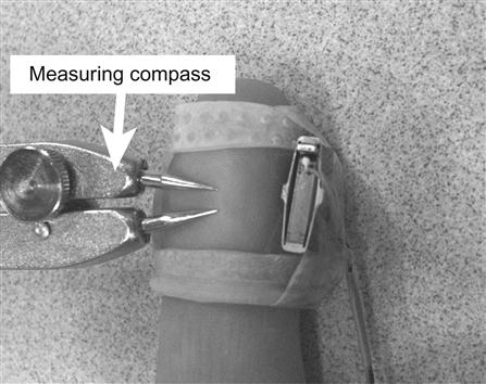
The subjects were instructed to place the hand with the sensorimotor enhancer attached on a table and close their eyes. The experimenter gently pressed two sharp points of a measuring compass against the palmar surface of each subject’s fingertip as shown in Figure 11. The subjects were asked to report when they felt definite contact from the two points. Two series of ascending and descending distances between the points (i.e., a total of four) were tested for each vibration condition, and the average was recorded as the result of each trial. The distance interval was 0.5 mm. The measured distance in the controlled case was normalized against the mean distance measured in the no-vibration case. Figure 12 shows the results of the experiments. The data show that the mean distances in all five controlled cases were smaller than that in the no-vibration case. The results of post hoc Dunnett testing also revealed significant differences against the no-vibration case for the 0.75T (p<0.01) and 1.0T (p<0.01) cases.

5.2.2 One-Point Touch Test
The subjects were instructed to place the hand with the sensorimotor enhancer attached on a table and close their eyes. The experimenter pressed a monofilament against the palmar surface of each subject’s fingertip until buckling occurred, held it, and then removed it. The subjects were asked to report when they felt contact from the filament. Two series of ascending and descending loads (i.e., a total of four) were tested for each vibration condition, and the average was recorded as the result of each trial. A total of five Semmes-Weinstein monofilaments (Touch-Test Sensory Evaluator; 0.008, 0.02, 0.04, 0.07, and 0.1 g) were used as stimuli. The measured load in the controlled case was normalized against the mean load measured in the no-vibration case. Figure 13 shows the results of the experiment. Smaller values of mean force equate to better tactile sensitivity. These outcomes show that the forces in all five controlled cases were smaller than that in the non-vibration case. The results of post hoc Dunnett testing also revealed significant differences against the non-vibration case for the 0.5T (p<0.01), 0.75T (p<0.01), and 1.0T (p<0.01) cases.

5.2.3 Active Sensory Test – Texture Discrimination
The subjects were asked to touch nine pieces of sandpaper with CAMI grit sizes of #40, #80, #120, #150, #180, #220, #240, #280, and #320 and select the one they judged to have the same texture as the piece on the other side. All the pieces were glued to one side of a plastic board provided to the subjects, who were not allowed to see the sandpaper but were permitted to touch and feel it. Attached to the other side of the board was a test piece of sandpaper with a grit size matching one of the nine sandpaper types. Figure 14 shows the results of the experiment. Higher ratios equate to better tactile sensitivity. As the figure indicates, the mean correct ratios for all the controlled cases tended to be higher than that of the no-vibration case. The results of post hoc Dunnett testing also revealed significant differences against the non-vibration case for the 0.5T (p<0.05) and 1.0T (p<0.05) cases.

5.2.4 Motor Skill Test – Minimal-Force Grasping
The subject was asked to pinch and hold an object with a weight of 140 g for 3 seconds with as little force as possible without allowing it to slip. The force measured in the controlled case was normalized against the mean force measured in the no-vibration case. Figure 15 shows the results of the experiment. Smaller forces equate to better motor performance in terms of pinch grasping. Improvements in motor performance were observed for all the controlled cases. The results of post hoc Dunnett testing also revealed significant differences against the no-vibration case for the 0.75T (p<0.01) and 1.25T (p<0.05) cases.

6 Conclusions
Haptic display represents a promising interface for human-computer interaction tools that provide users with nuanced information in a virtual environment. Humans utilize tactile and haptic information to determine object properties using thousands of mechanoreceptors located in the hands. Various haptic illusions can also be created by applying vibration and/or deformation to tactile mechanoreceptors. Improving haptic and tactile sensory capability helps to enhance motor performance. Such devices can be used to assist workers engaged in tasks requiring high-precision manual dexterity.
This chapter describes state-of-the-art wearable haptic display devices, and also introduces a variety of previously developed wearable devices that improve motor performance. In this chapter, two research studies are presented in detail. The first explored the challenge of displaying friction and weight illusions based on fingertip deformation. In this study, only phenomena occurring at the fingertips were considered. However, weight is sensed using not only tactile receptors in fingertips, but also proprioceptive information from muscles and tendons. Further investigation is necessary to understand human perception characteristics of weight and friction, and clarify the effects of tactile and haptic sensitivity on other types of motor performance. The second study investigated a wearable sensorimotor enhancer that improves tactile sensitivity in human fingertips. The development of a wearable device for fingertips is expected to assist individuals in workplaces, including those engaging in laboratory work with palpation for tumors, handling of very small objects, texture design for products, and high-precision manual assembly. Continued research in this area may also lead to the development of a novel device that helps individuals with incomplete peripheral neuropathy to use their hands more reliably in daily activities and at work.
The author hopes this chapter will be useful to anybody interested in wearable haptic and tactile devices.