By design, Terminal Server relies heavily on the network infrastructure of an organization to function effectively. The perceived stability of Terminal Server depends very much on the underlying stability and design of the network. A solid understanding of how to configure and deploy Terminal Server is only part of the criteria required for a successful implementation. If users are unable to maintain a reliable connection to the Terminal Server, the environment will be considered unusable from the perspective of both the users and the business.
NOTE:
If you’re unfamiliar with the general concepts of networking, see Appendix C, “Network Primer,” where I provide an introduction to network communications protocols and physical and logical networks.
Of course, ensuring that adequate network resources are available for an application or system deployment is certainly not a new concept. In the past, when planning an application deployment into your company’s existing network infrastructure, you would need to consider such things as the application’s traffic patterns to ensure that the network was designed to meet the application’s needs (or vice versa). In order to effectively access the impact of an implementation on your network, you need to be able to identify the strengths and weaknesses of your existing infrastructure and flag areas that may need to change in order to minimize bottlenecks or single points of failure.
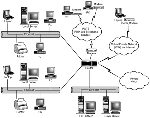
Consider Figure 4.1, which represents the historical network design concept known as the 80/20 rule. In this design, the majority (80 percent) of the communications for local clients is handled by local file servers and never traverses other network segments. Most (if not all) local services would be lost in the event of a local file server failure. Twenty percent of the traffic would still be destined for other network segments. This traffic would most likely include e-mail or access to other shared resources or services. The main reason for this type of segregation was to minimize the impact of packet collisions on a segment due to a large number of host nodes.
Multiple subnets within a corporate LAN would be created in order to isolate one group of users from another. Servers most often used by a particular user group would be located on the same subnet as those users in order to minimize the traffic passing through the routers to other subnets.
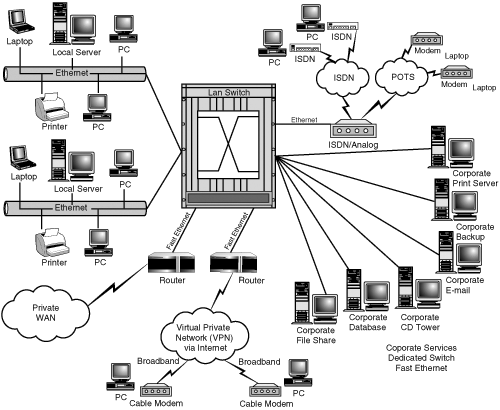
The increased complexity of today’s applications and their demands on the network, along with changes in how corporations have traditionally worked, has made the 80/20 configuration unrealistic for most modern networks. This has necessitated the redesign of existing networks and development of new ones by network engineers that can satisfy these new requirements. Cross-functional teams not physically co-located, support issues, server clusters, application-specific file servers, and the introduction of new internetworking devices have all contributed to this need. Figure 4.2 shows the shift in design theory and the migration to flat networks, in which the main function of the router now becomes that of isolation rather than the interconnection of network segments.
NOTE:
As the number of nodes on a network increases, the logical layout of a flat network itself can become unusable, mainly because all these nodes are in the same broadcast domain. A significant amount of traffic can be generated because of this, ultimately impacting the network. Instead of segregating the network using routers, which themselves add latency, the use of switching implemented with VLANS (virtual LANs) allows for the separation of broadcast domains without the latency overhead created by the traditional router.
VLANs group together devices on different physical LAN segments, while allowing the different hosts on each network to communicate with each other as if they were all on the same physical (flat) LAN segment.
One common mistake when planning a Terminal Server implementation is to assume that the network requirements are the same as for a traditional application deployment. Most network engineers won’t intuitively know the differences between Terminal Server and a regular application deployment and may plan network infrastructure changes that aren’t required, particularly if the existing environment is based around the 80/20 rule.
The way Terminal Server operates can allow for a continued return on investment (ROI) for existing networks. Unlike the traditional client/server relationships in which the desktop client communicates directly with the database server, Terminal Server creates an indirect communication path from the client to the Terminal Server and then from there to the destination database server. This is demonstrated in Figure 4.3, which depicts the data flow between the client, the Terminal Server, and the back-end database or file server.
As the figure shows, the database or file server is no longer in direct communication with the client. Instead, the communications occur between the client’s Terminal Server session and the appropriate back-end server. This creates a situation where the high-bandwidth requirements exist only between the Terminal Server and the data or file server.
Understanding the data flow patterns and required resources for the applications that you’ll be putting on Terminal Server will help determine the deployment strategies for your implementation. You need to ensure that bandwidth has been maximized between the Terminal Server(s) and the database/file server(s) that the applications will utilize. Very often this involves co-locating these servers onto a high-speed backbone to provide dedicated bandwidth, reduce latency, and improve scalability and fault tolerance.
NOTE:
To sum up, good Terminal Server design dictates that Terminal Servers and back-end servers should occupy the same LAN segment whenever possible.
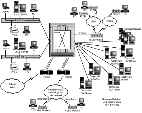
With the lower bandwidth requirements between the client and the Terminal Server (discussed further in the “Latency and Network Utilization on Client Performance” section of this chapter), local area networks (LANs) based on the 80/20 rule of the flat network model can often be used with a Terminal Server implementation without the costly requirements of an infrastructure change. Figure 4.4 illustrates how the network from Figure 4.1 might look after a Terminal Server implementation. The previously distributed servers have now been centralized on the same network as the Terminal Servers. This setup allows for fast local access to the required resource through Terminal Server. The existing client networks now have to support only the desired presentation protocol (ICA or RDP) traffic.
Figure 4.5 shows a similar configuration with a flat network implementation with Terminal Server. In most situations the centralized servers are connected via Fast Ethernet (100 Mbps) or Gigabit Ethernet (1000 Mbps), with shared client segments connected to a backbone router or switch.
The concepts discussed to this point with regard to Terminal Server and the LAN can be extended to include the wide area network (WAN). Today the more costly WAN lines are under siege from the amount of traffic that’s being forced over them. Situations in which clients are accessing network resources located in a separate building—or sometimes even miles away in a separate city—are becoming more common. As a result, companies are forced to keep up by acquiring higher bandwidth connections through leases or other means.
Through the proper deployment of Terminal Server in a WAN configuration, RDP or ICA can help to greatly reduce the bandwidth requirements of the existing WAN and extend its ROI. To do this successfully, it’s important to have a clear idea of the existing bandwidth available, possible latency issues, and the data flow requirements of the clients and their applications.
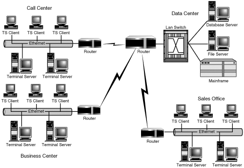
Figure 4.6 illustrates a not-so-uncommon mistake made when wide-area deployments of Terminal Server are being planned. The mistake is in co-locating the Terminal Servers with the clients instead of with the data servers. By placing the server local to the client, you’re forcing the Terminal Server to cross a WAN connection in order to access the required resources, resulting in the same bandwidth requirements that existed prior to Terminal Server. On further inspection, it’s clear that this isn’t the optimal solution.
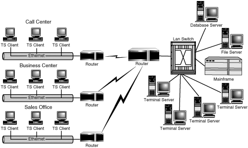
Figure 4.7 depicts resource allocation and deployment providing the best use of wide-area bandwidth. Using this deployment strategy, only the RDP and ICA traffic will traverse the wide-area connections. All the bandwidth-intensive processing requirements are at the same physical location as the high-speed switched backbone.
NOTE:
In a scenario such as the one depicted in Figure 4.7, there may be an opportunity to reevaluate the current bandwidth requirements for the WAN links in light of the introduction of Terminal Server traffic and the removing of most other network traffic between sites. Of course most organizations are rarely interested in reducing their current bandwidth requirements but instead are more likely trying to find ways to avoid having to increase them.
Figure 4.7 demonstrates what I consider an ideal scenario for implementing Terminal Server over a WAN. Most often you won’t have the luxury of migrating all resources into one location, whether for resource or business reasons. In this situation you need to carefully review what resources can and can’t be moved and position the Terminal Servers accordingly. You may also want to investigate dividing your Terminal Server environment between two or more locations. MetaFrame’s server farm feature spans physical networks, allowing for a divided server environment with very little increase in administrative complexity. MetaFrame implementation planning is discussed in Chapter 8, “Server Installation and Management Planning.”
Figure 4.8 shows an example of Terminal Servers divided between two locations. One set of Terminal Servers resides at the corporate head office, running a client/server application that accesses a database server, which is also at that location. These Terminal Servers are used solely by the sales office that’s also on the same network (Sales Office #2). The data center contains the remainder of the Terminal Servers that make up the environment. This type of configuration lends itself well to MetaFrame’s support for distributed server farms. You could also use RDP in this scenario, but the user would be required to maintain two separate desktops (one for each location) or would have to run the applications within RDP session windows.
NOTE:
Client configurations are discussed in Chapter 5, “Client Hardware and Software Planning.”
One issue that becomes immediately apparent with the centralization of the environment to support Terminal Server is the creation of single points of failure. Look again at Figure 4.8 in the preceding section. If the WAN link to the corporate office goes down, Sales Office #1 will not be able to access any published applications from that location. There are two ways that you can attempt to deal with this problem:
Develop redundancy in the network to eliminate the single points of network failure. The addition of a WAN link directly from Sales Office #1 to the head office would provide a redundant link to protect against failure.
Maintain a duplicate Terminal Server environment in a different location that’s also accessible. If one site is lost, the other is still available to support user requests. By placing a set of Terminal Servers plus the database server at Sales Office #1, you would protect against all WAN failures.
In almost every situation, the first of these solutions is the preferred method, from both a cost and a logistics standpoint. Duplicating the Terminal Server environment would probably also require a means of replicating the information between the two database servers, which in turn would result in increased bandwidth requirements. The creation of a low-bandwidth redundant WAN link directly between the two sites would be much more cost effective and much easier to manage.
You should carefully evaluate the requirements for redundancy in your WAN and what risks are associated with each possible failure point. By highlighting the critical interconnections, you can then look to position the Terminal Servers so as to best minimize these redundancy requirements.
NOTE:
In addition to single points of failure in your network infrastructure, you may have these vulnerabilities in your server layout itself. Dependencies on a single domain controller or file server can also be weaknesses in the planning and design of your environment. In Chapter 6, “Terminal Server Hardware Planning,” I talk about identifying and accounting for those potential weaknesses in the environment.
Although one of the highly touted features of Terminal Server is its ability to function well over low-bandwidth connections, it’s still critical that reliable, sustained communication channels exist between the client and the Terminal Server. One of the most important network requirements for Terminal Server is minimizing the latency in the client connection to the server. Latency is critical because of the impact it can have on the user’s perceived server or application performance. Latency manifests itself to the user as sluggish screen updates or unresponsive keyboard or mouse input.
NOTE:
When latency is an issue in the environment, users encounter situations in which they can move the mouse pointer around the desktop but can’t click anything or provide keyboard input to the Terminal Server session. This is because the local mouse tracking is handled by the client independently of data being sent to or received from the server.
High latency can also result in client disconnects from the Terminal Server. For optimal user interaction with the Terminal Server, latency should be kept under 100ms. At 150ms, users experience a decline in responsiveness, and anything over 300ms will usually result in severe client performance issues. If data packets are actually being lost between the client and the server, then it is likely that the user will experience a disconnection from the Terminal Server session. Keeping the average utilization in a network segment to less than 30 percent will help minimize latency on that segment.
TIP:
A simple latency test is to use ping to gather average round-trip times between a computer on the client network and one on the server network. For example, on a Windows system the following command would ping the IP address 192.168.3.1 one hundred times with packets 1KB in size and pipe the output to a text file called out.txt:
ping –t –n 100 –l 1000 192.168.3.1 > out.txt
You can then average the round-trip times to get an idea as to the average latency in your network. While not exact, the results will certainly give you an idea as to whether potential latency problems may exist. The following example shows a sample output from a ping test that shows some high round-trip times and even a few time-outs, which would indicate that there could potentially be some speed and connectivity issues over this WAN link.
H:>ping -t -n 100 -l 1000 192.168.3.1
Pinging 192.168.3.1 with 1000 bytes of data:
Request timed out.
Reply from 192.168.3.1: bytes=1000 time=109ms TTL=126
Reply from 192.168.3.1: bytes=1000 time=94ms TTL=126
Request timed out.
Reply from 192.168.3.1: bytes=1000 time=125ms TTL=126
Reply from 192.168.3.1: bytes=1000 time=93ms TTL=126
Reply from 192.168.3.1: bytes=1000 time=94ms TTL=126
Request timed out.
Reply from 192.168.3.1: bytes=1000 time=109ms TTL=126
Reply from 192.168.3.1: bytes=1000 time=94ms TTL=126
Request timed out.
Reply from 192.168.3.1: bytes=1000 time=109ms TTL=126
Reply from 192.168.3.1: bytes=1000 time=94ms TTL=126
Reply from 192.168.3.1: bytes=1000 time=94ms TTL=126
Request timed out.
Reply from 192.168.3.1: bytes=1000 time=109ms TTL=126
Reply from 192.168.3.1: bytes=1000 time=94ms TTL=126
Reply from 192.168.3.1: bytes=1000 time=94ms TTL=126
Reply from 192.168.3.1: bytes=1000 time=1188ms TTL=126
Reply from 192.168.3.1: bytes=1000 time=94ms TTL=126
Reply from 192.168.3.1: bytes=1000 time=110ms TTL=126
Reply from 192.168.3.1: bytes=1000 time=94ms TTL=126
Reply from 192.168.3.1: bytes=1000 time=1016ms TTL=126
Request timed out.
Reply from 192.168.3.1: bytes=1000 time=125ms TTL=126
Reply from 192.168.3.1: bytes=1000 time=78ms TTL=126
Reply from 192.168.3.1: bytes=1000 time=94ms TTL=126
Reply from 192.168.3.1: bytes=1000 time=188ms TTL=126
Reply from 192.168.3.1: bytes=1000 time=94ms TTL=126
Reply from 192.168.3.1: bytes=1000 time=78ms TTL=126
Reply from 192.168.3.1: bytes=1000 time=94ms TTL=126
Reply from 192.168.3.1: bytes=1000 time=94ms TTL=126
Reply from 192.168.3.1: bytes=1000 time=94ms TTL=126
Reply from 192.168.3.1: bytes=1000 time=94ms TTL=126
Reply from 192.168.3.1: bytes=1000 time=109ms TTL=126
Reply from 192.168.3.1: bytes=1000 time=157ms TTL=126
Reply from 192.168.3.1: bytes=1000 time=110ms TTL=126
Reply from 192.168.3.1: bytes=1000 time=94ms TTL=126
Request timed out.
Reply from 192.168.3.1: bytes=1000 time=109ms TTL=126
Reply from 192.168.3.1: bytes=1000 time=94ms TTL=126
Reply from 192.168.3.1: bytes=1000 time=532ms TTL=126

Ping statistics for 192.168.3.1:
    Packets: Sent = 42, Received = 35, Lost = 7 (16% loss),
Approximate round trip times in milli-seconds:
    Minimum = 78ms, Maximum = 1188ms, Average = 144ms
Both RDP and ICA have similar utilization requirements, with an average of about 20Kbps per connected user session. The exact value depends on a number of factors, including compression, bitmap caching, client device-mapping features, and printing requirements. In many situations, 20Kbps is above the average requirement but can still serve as a marker for the upper threshold of concurrent user load—particularly over lower bandwidth connections such as 56K frame relay or ISDN.
A more accurate utilization assessment will require performing some analysis in a test environment running the applications that you intend to deploy. The applications that will be used have an impact on the overall utilization of the client. In general, highly graphical applications have higher requirements than simple word-processing applications, but in some cases this may not be true. For those users who are proficient typists, even text-based applications will appear to lag behind while they are typing.
TIP:
Citrix has introduced features specifically designed to help mitigate the effects of latency on the user’s computing experience. Collectively they are called SpeedScreen Latency Reduction features, and these will be discussed in Chapter 5.
Detailed data collection can provide some very realistic numbers on the expected bandwidth requirements, but the time required to prepare and implement such a test scenario is rarely a luxury that an administrator will have. Performing some initial estimates based on an average utilization between 12Kbps and 25Kbps will give an idea as to what load can be expected across a WAN link before latency will become a factor.
If, for example, you were trying to determine how much bandwidth would be required to support 45 users over a wide-area link, you would use the following calculation to evaluate this bandwidth requirement.
Let’s assume that at the low end 12Kbps was the average utilization per client. In order to determine the necessary bandwidth you can’t simply multiply 12Kbps by 45, which gives 540Kbps. Remember that keeping the average utilization under 30 percent will help minimize latency. So in order to take this into consideration we need to use the following formula to derive the proper bandwidth requirement.
where
B = Total bandwidth required in Kbps |
C = Number of client nodes |
A = Average utilization per node in Kbps/client |
P = Percentage utilization cap |
So with an average utilization per node of 12Kbps, the desired number of client nodes at 45 and a utilization percentage cap of 30 percent (0.3), the necessary bandwidth is

So in order to support 45 users with an average of 12Kbps and a percentage cap of 30 percent, you’re looking at needing 1800Kbps (about 2 Mbps) of bandwidth—double that if you were to take the high estimate of 25Kbps per user.
For the TCP/IP protocol, Table 4.1 lists the following well-known RDP and ICA ports:
TIP:
It is expected that Microsoft will introduce support for RDP via SSL with the release of SP1 for Windows Server 2003, in which case the RDP protocol would also support access via TCP port 443.
Table 4.1. RDP and ICA Well-Known Installation Ports
Function | Port Number | |
|---|---|---|
ICA | Listening port for client connections utilizing the session reliability feature. | TCP:2598 |
RDP | Listening port for client connections | TCP:3389 |
Load balancing (using Microsoft Network Load Balancing) | UDP:2504 | |
ICA | Listening port for client connections | TCP:1494 |
Legacy ICA Browsing (TCP/IP) | UDP:1604 | |
HTTP server farm listening port | TCP:80 | |
HTTPS Citrix SSL Relay listening port | TCP:443 |
The various Citrix listening ports (except for the UDP port) can all be modified from their default by using the appropriate command. The client connection port is modified using the ICAPORT command (or the Management Console if using session reliability), the HTTP port is modified during the MetaFrame installation or using the CTXXMLSS command, while the HTTPS port is modified using the Citrix SSL Relay control application on the appropriate MetaFrame server. Whenever a port number is modified from the default, the ICA client must be updated to point to this alternate port. Port redirection settings are discussed in Chapters 5, “Client Hardware and Software Planning,” and Chapter 20, “ICA Client Installation and Configuration.” Please see Appendix B, “MetaFrame Presentation Server Command Reference,” for more information on the ICAPORT and CTXXMLSS commands.
The RDP client connection listening port can also be modified, but this must be done by altering the registry on the Terminal Server and modifying the connection file on the client. There is no GUI tool available to manage this function.
As mentioned in Chapters 1 and 2, the following network protocols are supported by the RDP and ICA presentation protocols:
ICA supports TCP/IP, IPX, SPX, and NetBEUI on Windows 2000 but only TCP/IP on Windows Server 2003.
RDP supports only TCP/IP on both Windows 2000 and Windows Server 2003.
Regardless of which client or protocol is used to connect to a Terminal Server, once the user session has been established on the server, that user can access any available network resources using any of the network protocols installed on the Terminal Server.
For example, a user could use the RDP client to connect via TCP/IP to a Windows 2000 Terminal Server that’s running both TCP/IP and the NWLink IPX/SPX protocol. Once connected, the user could use IPX to connect to any valid NetWare file server. The user session would communicate with the NetWare server using IPX, while Terminal Server and the client session communicate using TCP/IP.
An important requirement for almost any user is the ability to print. With Terminal Server, you need to pay particular attention to both the location of printers and how clients will access them. Figure 4.9 shows a typical WAN scenario with printers situated locally on each client network. When a user in this scenario wants to print to a local printer from the Terminal Server session, the print job has to traverse the WAN to reach the desired printer.
All printing requires additional network bandwidth. The exact amount depends on how often users are printing and what they’re printing. The larger or more complex the print job, the more bandwidth required. One thing you can do is distribute clients, Terminal Servers, print servers, and printers in such a way as to minimize the amount of network travel required to get the print job to the printer. There are three common scenarios for providing a client access to printers from within Terminal Server:
Remote WAN print server
Local (or remote) LAN print server
Redirected client printing
The following sections look at each of these scenarios in more detail.
In this configuration, a print server is located on the same network as the user. When the user prints from within Terminal Server, the server sends the print job directly to the print server. I usually refer to this configuration as “remote WAN print server” because the print server is located across a WAN link from the Terminal Server and the print job is destined for the remote network, as shown in Figure 4.10. This is a common configuration for an existing Windows implementation, since the print server is most often located on the same network as the printers it’s supporting.
When a print job is initiated on the Terminal Server, the data normally is not spooled on the Terminal Server but instead passes immediately to the remote print server, where it’s spooled for printing to the appropriate printing device.
The Remote WAN print server configuration is preferred if users on the remote network will need access to print from their local desktops. For example, if you’re making Office XP available through Terminal Server, but users will continue to run AutoCAD locally, they still need to be able to print from AutoCAD to their printer. This configuration ensures that local printer traffic isn’t unnecessarily crossing the WAN. Remember, print jobs that are initiated from within Terminal Server are crossing the WAN only once, on their way from the Terminal Server to the print server.
If users need to run completely from within Terminal Server with no local printing requirements, consider the next scenario, Local LAN print server.
In this configuration, the print server is located on the same network as the Terminal Server (see Figure 4.11). Print jobs are sent from the Terminal Server to the print server, where they’re spooled and then sent to the physical printer located either on the LAN or across a WAN link. I refer to this as the “Local LAN print server configuration” because the print server is located on the same network as the Terminal Server. Jobs in this configuration are destined for either the local network or the remote network, depending on where the printer resides.
Local LAN print server is the standard configuration when both clients and servers are situated within a single flat network, such as the one shown earlier in Figure 4.2, or possibly an 80/20 LAN configuration as shown in Figure 4.1, since no WAN links exist.
When clients are separated from the Terminal Servers by a WAN link, this scenario is valid only if all remote clients are performing all processing from within Terminal Server and don’t require the ability to print directly from their local client device. If local printing was required, the user’s print job would traverse the WAN twice to print: first from the client to the print server and then back again from the print server to the physical printer.
The third scenario involves users printing directly to a printer configured on the local client device. There are two ways that this can be done:
Use regular Microsoft Networking to create a network printer share on the client device so that it can then be reached from within a Terminal Server session. Of course, this is only valid for Windows-based clients (excluding most non-Windows-based terminals).
Use the automatic client printer-mapping feature available with both the RDP and ICA clients. Client printer mapping allows any printer that has been configured on the local client (either locally attached or through a network share) to automatically be configured and available from within the user’s Terminal Server session.
Figure 4.12 demonstrates the print job flow in the redirected client printer scenario when the client is situated across a router. The exact same steps will occur if the client is located on the same physical network as the Terminal Server.
While the specifics differ on how ICA and RDP handle client printer mappings, the general job flow is similar. The print job is processed on the Terminal Server and directed to the client, which then performs one of the following actions:
If the printer is locally attached, the job is spooled on the client and sent to the printer.
If the printer is a network printer, the job is redirected to the appropriate print server, where it’s spooled and printed. When network printer redirection is occurring you need to be certain that the client is not redirecting the print job back to a network printer across a WAN link. If this is the case, you may need to look at using the local or remote LAN print server configuration. MetaFrame includes a customizable feature that will automatically route network redirected printers directly to the network-based print queue, bypassing the client completely.
Redirected client printing is most useful in two situations:
When clients have printers that are directly connected to their computers—. Client printer mappings provide a seamless way to access a locally attached printer without the user having to create a network share.
When used in conjunction with one or more published applications running in a seamless window—. When an application is in a seamless window, it appears to the user to be running locally. Client printer mapping enables the user to consistently access the same printer configuration regardless of whether the application is locally installed or accessed through a MetaFrame server. Seamless window functionality was discussed in Chapter 2, “Citrix MetaFrame Presentation Server.”
While high-speed Internet connectivity continues to become more readily available to the mobile and remote user (broadband access in hotels and mobile connectivity “hotspots” are just two examples), there is still a need in many organizations to either provide direct dial-up access or to at least attempt to accommodate those users who may be able to access the office remotely only by using a dial-up connection (landline or cellular-based).
The low-bandwidth requirements of Terminal Server make it well suited to providing remote users with access to applications and data within your environment. This can have great appeal to many organizations because the data itself never has to leave the internal network—only the visual representation is sent to the client.
Citrix’s WinFrame product, the first multiuser-based version of Windows NT, was originally developed and marketed as a dial-up solution, allowing dial-up users to have LAN-like access to Windows applications such as Microsoft Mail. While the latest generation of this product contains many new features and enhancements, the basic advantages of accessing the product over a dial-up connection still exist. Referring once again to Figure 4.1 or Figure 4.2, notice the typical dial-up configuration in an environment with Terminal Server.
From a network-planning standpoint, very little needs to be done to provide dial-up access to a Terminal Server environment, and there are multiple configuration scenarios that can be implemented:
Users dial up to their local ISP, establish an Internet connection, and then connect into the Terminal Server environment through the Internet. Internet-based connectivity is discussed in the next section.
Users dial directly into a remote access solution, typically a bank of modems that then let the user establish a presence on the network, allowing the user’s remote PC to become a host on the internal network. Once this connection has been established, the user can use either the RDP or ICA client to access the Terminal Server. Most of the remote access solutions will let the client use either the TCP/IP or NetBEUI protocols. If you intend to use the RDP client or are running Windows Server 2003, you must implement TCP/IP support for the dial-up connection. ICA running on Windows 2000 will support the NetBEUI protocol.
A third dial-up option is to directly access the Terminal Server using either Microsoft’s RAS solution installed on the Terminal Server or using the ICA client dial-in option available on a per-connection basis with MetaFrame. Figure 4.13 shows an asynchronous ICA connection entry that was created in the Terminal Services Configuration utility. Direct dial-up ICA connections can be created only on Windows 2000 MetaFrame servers. I recommend one of these strategies only for very small Terminal Server implementations, as they don’t provide the same robust network support that dedicated dial-up products can provide and place extra resource requirements on the Terminal Server itself.
Today, many organizations are leveraging the availability of the Internet to provide connectivity between remote offices or mobile users and corporate data centers. This is particularly appealing for small- to medium-sized corporations that don’t have the resources to acquire dedicated WAN links between remote offices. In Chapter 14, “MetaFrame Presentation Server Configuration,” I talk in detail about configuring Web-based access to MetaFrame Presentation Server.
NOTE:
Over the past few years a new service industry known as the application service provider (ASP) has emerged that leverages the Web-based technology available with Terminal Server, MetaFrame, and other products such as Tarantella. As the name suggests, an ASP provides its customers with access to a set of applications through a thin-client solution. Instead of the client purchasing the software and installing it on the local computer, the client leases or rents access to the applications and disk space to store data. This lets organizations such as law or accounting firms have access to the latest software without the requirements of an in-house information technology (IT) department. A low monthly fixed cost, usually bundled with support, is one of the key selling points of an ASP.
You can find out more about ASPs by visiting the Citrix Web site at http://www.citrix.com or other sources such as ASP News at http://www.aspnews.com.
Providing connectivity to Terminal Server via the Internet has its own set of challenges that must be considered carefully. The two areas of focus are security and connectivity.
The number-one issue with providing access to your Terminal Server environment over the Internet is security. Simply stated, your goal is to let only authorized users access your environment. The type and extent of security you implement will depend on the size of your organization, what services you want to provide through Terminal Server, and the money you have available to spend. There are three main configurations you can implement to provide access to Terminal Server:
Most other Internet configurations are simply a variation on one of these configurations. I suggest that if you’re not familiar with firewalls or Internet security you enlist the assistance of someone who is. There’s very little room for error when establishing a secure presence on the Internet.
Figure 4.14 shows a typical topology for implementing Internet security. In addition to the obligatory firewall, there is what’s called the demilitarized zone (DMZ). A DMZ is a network that’s either sandwiched between two firewalls, as shown here, or in some situations sits out in the open directly off of the router. In either situation, the DMZ exists as a location where resources that need to be accessed by clients on the Internet can be placed. Access to an external resource doesn’t automatically grant them access to the internal network. This way, if a malicious attack compromises the security of an external resource in the DMZ, it doesn’t mean that your internal security has been compromised. Without a DMZ, your internal network would be at risk.
The DMZ shown in Figure 4.14 is commonly referred to as a single-stage or one-hop DMZ, because there is only one stage of restriction between the Internet and the internal network. There is also what is known as a two-stage or double-hop DMZ. Figure 4.15 provides an example of this, where less secure services such as FTP are placed in the outer stage, and more secure or restrictive services are placed in the inner stage.
One of the drawbacks to the DMZ configurations shown in Figures 4.14 and 4.15 is that there usually are many access points open from the DMZ into the internal network, particularly Windows network-related ports for file access, SQL Server access, and so on. The potential dangers of opening such ports will usually outweigh such a configuration, limiting its usefulness as an access method for remote user connectivity into the internal network. In the past this would usually mean that either a VPN-based solution or direct Terminal Server access, both described shortly, would be implemented instead.
Fortunately, alternatives exist that will allow the deployment of a proxy-based server into the DMZ that is responsible for connecting and rerouting incoming external clients through the firewall and into the appropriate server on the internal network. Figure 4.16 shows an updated, conceptual, single-stage DMZ diagram showing these servers in place. Citrix provides what is known as the Secure Gateway for MetaFrame Presentation Server, a security solution that allows for a secure method of access and authentication for users wanting to access the secured internal network from the Internet.
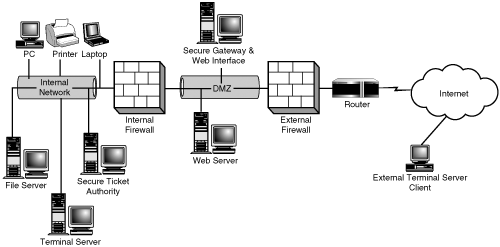
Figure 4.16. Secure Gateway for MPS provides secure access from the Internet to internal MetaFrame servers.
NOTE:
A couple of issues can arise when relying on access to a Terminal Server/MetaFrame environment through a firewall:
When firewalls are configured to perform some types of deep-packet inspection, they can introduce a small overhead in the communications pathway between the client and the server. This additional latency must be taken into consideration when evaluating the responsiveness of the Terminal Server environment in this scenario.
The firewall can also introduce a single point of failure into your connectivity pathway if redundancy and fail-over provisioning has not been implemented. If you are going to rely on a firewall’s availability in order to provide remote access to your production users, you will need to be certain that any load-balancing or failover support has also been implemented.
TIP:
The configuration and use of Secure Gateway for MPS and Web-based access to your MetaFrame server farm are discussed in detail in Chapter 14.
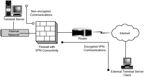
One alternative to placing Terminal Servers into a DMZ is to implement a virtual private network (VPN) solution. VPNs have become increasingly popular as the technology has become more stable and secure on the Microsoft platform. A VPN can be thought of as a special case of dial-up access through the Internet. A client on the network establishes a connection to a corporate VPN server visible on the Internet. The VPN encapsulates all data sent between the two points within encrypted packets that hide the actual communications going on between the client and the server. Figure 4.17 shows a VPN between a client on the Internet and a Terminal Server located within the internal network.
VPNs are also used to create extranets. An extranet is two or more private networks connected through an unsecured (public) network such as the Internet. A VPN connection exists between the private networks, allowing them to talk securely with each other.
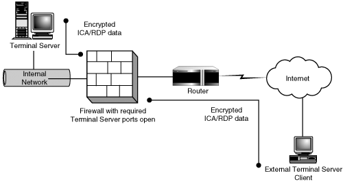
Although I use the term direct, in a direct Terminal Server access setup, the Terminal Servers themselves are not directly connected to the Internet but are accessed through a firewall that has the required ports open only to the specific Terminal Server IP addresses. Figure 4.18 shows this configuration, which is similar in appearance to the VPN example in the preceding section. The one difference is that the security is enforced through the high encryption (either RDP or ICA) of the Terminal Server connection and not through the VPN.
The biggest weakness in this configuration is the passwords used by the users. Unless strong passwords are enforced, a hacker with the necessary ICA or RDP client has only to guess an account and password to gain access to your environment. Additional policies and restrictions on the firewall can help reduce an unauthorized person’s ability to reach the logon prompt and allow access only if the user is coming from a static location or using additional client-side firewall security settings.
Direct Terminal Server connectivity is best implemented as an alternative to the VPN solution when there are only a few remote users requiring access to your Terminal Server environment. For most other situations, I would look to using some form of Web interface that has been secured with SSL for the corresponding Terminal Server client deployment.
The final point to touch on in this chapter is the importance of remembering that whenever you’re utilizing a public network such as the Internet, you’re not in control of latency, bandwidth, or overall stability. All these factors must be taken into consideration when you are trying to determine how your remote users will connect into the main Terminal Server environment. When you have mobile or roaming users, their options are fairly limited. The user can establish an Internet connection from their current location using high-speed (or dial-up) and then connect through via the Internet, or they can perform a direct dial into the environment where the Terminal Servers are located.
When connecting a remote office, if your users require a very high level of uptime due to the critical nature of the applications, you may need to forgo the use of an extranet client running over the Internet and instead look at the use of dedicated connectivity between the sites over leased lines in order to ensure a predefined quality of service (QOS) is being met.
In most cases, if your remote users will be establishing an Internet presence through the same ISP as the one your business is using, connectivity is more reliable than if the user were connecting through a different ISP. Terminal Server is much less forgiving about changes in bandwidth than other Internet applications such as FTP or a Web browser, so it is extremely important that a minimum acceptable baseline is developed.
