Chapter 4
Symmetric Block Ciphers
This chapter deals with some important block ciphers that have been developed in the past. They are IDEA (International Data Encryption Algorithm; 1992), RC5 (1995), RC6 (1996), DES (Data Encryption Standard; 1977), and AES (Advanced Encryption Standard; 2001). The AES specifies an FIPS-approved symmetric block cipher, which will soon come to be used in lieu of Triple DES or RC6.
4.1 Data Encryption Standard (DES)
In the late 1960s, IBM initiated a Lucifer research project, led by Horst Feistel, for computer cryptography. This project ended in 1971 and LUCIFER was first known as a block cipher that operated on blocks of 64 bits, using a key size of 128 bits. Soon after this IBM embarked on another effort to develop a commercial encryption scheme, which was later called DES. This research effort was led by Walter Tuchman. The outcome of this effort was a refined version of Lucifer that was more resistant to cryptanalysis.
In 1973, the National Bureau of Standards (NBS), now the National Institute of Standards and Technology (NIST), issued a public request for proposals for a national cipher standard. IBM submitted the research results of the DES project as a possible candidate. The NBS requested the National Security Agency (NSA) to evaluate the algorithm's security and to determine its suitability as a federal standard. In November 1976, the DES was adopted as a federal standard and authorized for use on all unclassified US government communications. The official description of the standard, FIPS PUB 46, Data Encryption Standard was published on 15 January 1977. The DES algorithm was the best one proposed and was adopted in 1977 as the DES even though there was much criticism of its key length (which had changed from Lucifer's original 128 bits to 64 bits) and the design criteria for the internal structure of DES, that is, S-box. Nevertheless, DES has survived remarkably well over 20 years of intense cryptanalysis and has been a worldwide standard for over 18 years. The recent work on differential cryptanalysis seems to indicate that DES has a very stronginternal structure.
Since the terms of the standard stipulate that it be reviewed every 5 years, on 6 March 1987, the NBS published in the Federal Register a request for comments on the second 5-year review. The comment period closed on 10 December 1992. After much debate, DES was reaffirmed as a US government standard until 1992 because there was still no alternative for DES. The NIST again solicited a review to assess the continued adequacy of DES to protect computer data. In 1993, NIST formally solicited comments on the recertification of DES. After reviewing many comments and technical inputs, NIST recommended that the useful lifetime of DES would end in the late 1990s. In 2001, the AES, known as the Rijndael algorithm, became an FIPS-approved advanced symmetric cipher algorithm. AES will be a strong advanced algorithm in lieu of DES.
The DES is now a basic security device employed by worldwide organizations. Therefore, it is likely that DES will continue to provide network communications, stored data, passwords, and access control systems.
4.1.1 Description of the Algorithm
DES is the most notable example of a conventional cryptosystem. Since it has been well documented for over 20 years, it will not be discussed in detail here.
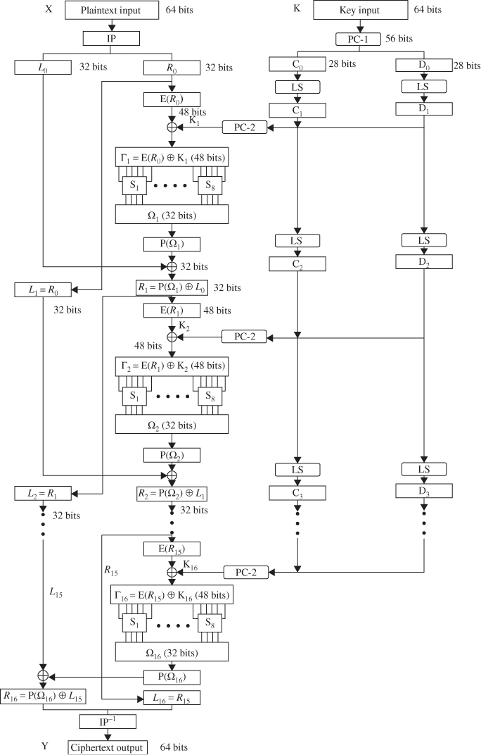
DES is a symmetric block cipher, operating on 64-bit blocks using a 56-bit key. DES encrypts data in blocks of 64 bits. The input to the algorithm is a 64-bit block of plaintext and the output from the algorithm is a 64-bit block of ciphertext after 16 rounds of identical operations. The key length is 56 bits by stripping off the 8 parity bits, ignoring every eighth bit from the given 64-bit key.
As with any block encryption scheme, there are two inputs to the encryption function: the 64-bit plaintext to be encrypted and the 56-bit key. The basic building block of DES is a suitable combination of permutation and substitution on the plaintext block (16 times). Substitution is accomplished via table lookups in S-boxes. Both encryption and decryption use the same algorithm except for processing the key schedule in the reverse order.
The plaintext block X is first transposed under the initial permutation IP, giving ![]() . After passing through 16 rounds of permutation, XORs, and substitutions, it is transposed under the inverse permutation
. After passing through 16 rounds of permutation, XORs, and substitutions, it is transposed under the inverse permutation ![]() to generate the ciphertext block Y. If
to generate the ciphertext block Y. If ![]() denotes the result of the
denotes the result of the ![]() th round encryption, then we have
th round encryption, then we have

The ![]() th round encryption of DES algorithm is shown in Figure 4.1. The block diagram for computing the f(
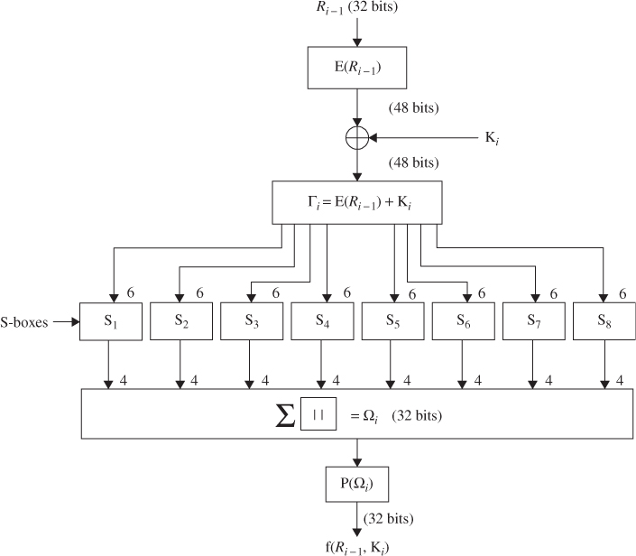
th round encryption of DES algorithm is shown in Figure 4.1. The block diagram for computing the f(![]() ) function is shown in Figure 4.2. The decryption process can be derived from the encryption terms as follows:
) function is shown in Figure 4.2. The decryption process can be derived from the encryption terms as follows:
Figure 4.1 The ![]() th round of DES algorithm.
th round of DES algorithm.
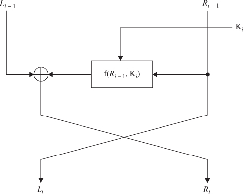
Figure 4.2 Computation of the f function.

If the output of the ![]() th round encryption is
th round encryption is ![]() , then the corresponding input to the (16–
, then the corresponding input to the (16–![]() )th round decryption is
)th round decryption is ![]() . The input to the first-round decryption is equal to the 32-bit swap of the output of the sixteenth round encryption process. The output of the first-round decryption is
. The input to the first-round decryption is equal to the 32-bit swap of the output of the sixteenth round encryption process. The output of the first-round decryption is ![]() , which is the 32-bit swap of the input to the sixteenth round of encryption.
, which is the 32-bit swap of the input to the sixteenth round of encryption.
4.1.2 Key Schedule
The 64-bit input key is initially reduced to a 56-bit key by ignoring every eighth bit. This is described in Table 4.1. These ignored 8 bits, ![]() , are used as a parity check to ensure that each byte is of old parity and no errors have entered the key.
, are used as a parity check to ensure that each byte is of old parity and no errors have entered the key.
Table 4.1 Permuted choice 1 (PC-1)

After the 56-bit key is extracted, they are divided into two 28-bit halves and loaded into two working registers. The halves in registers are shifted left either one or two positions, depending on the round. The number of bits shifted is given in Table 4.2.
Table 4.2 Schedule for key shifts

After being shifted, the halves of 56 bits (![]() ,
, ![]() ),
), ![]() , are used as the key input to the next iteration. These halves are concatenated in the ordered set and serve as input to the permuted choice 2 (Table 4.3), which produces a 48-bit key output. Thus, a different 48-bit key is generated for each round of DES. These 48-bit keys,
, are used as the key input to the next iteration. These halves are concatenated in the ordered set and serve as input to the permuted choice 2 (Table 4.3), which produces a 48-bit key output. Thus, a different 48-bit key is generated for each round of DES. These 48-bit keys, ![]() ,
, ![]() ,
, ![]()
![]() , are used for encryption at each round in the order from
, are used for encryption at each round in the order from ![]() through
through ![]() . The key schedule for DES is illustrated in Figure 4.3.
. The key schedule for DES is illustrated in Figure 4.3.
Table 4.3 Permuted choice 2 (PC-2)
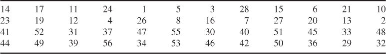
Figure 4.3 Key schedule for DES.

With a key length of 56 bits, these are ![]() possible keys. Assuming that, on average, half the key space has to be searched, a single machine performing one DES encryption per microsecond would take more than 1000 years to break the cipher. Therefore, a brute-force attack on DES appears to be impractical.
possible keys. Assuming that, on average, half the key space has to be searched, a single machine performing one DES encryption per microsecond would take more than 1000 years to break the cipher. Therefore, a brute-force attack on DES appears to be impractical.
Using Table 4.2, the blocks ![]() and
and ![]() are obtained from the block
are obtained from the block ![]() and
and ![]() , respectively, by shifting 1 bit to the left as follows:
, respectively, by shifting 1 bit to the left as follows:
The 48-bit key ![]() is derived using Table 4.3(PC-2) by inputting the concatenated block
is derived using Table 4.3(PC-2) by inputting the concatenated block ![]() such that
such that ![]() .
.
![]()
Using Table 4.3 (PC-2), the 48-bit key ![]() at round 2 is computed as
at round 2 is computed as ![]() . Similarly,
. Similarly, ![]() is generated from shifting
is generated from shifting ![]() by 2 bits to the left as follows:
by 2 bits to the left as follows:
![]()
Using Table 4.3, we have
![]()
In a similar fashion, all the other 16-round keys can be computed and the set of entire DES keys is listed as follows:
4.1.3 DES Encryption
DES operates on a 64-bit block of plaintext. After initial permutation, the block is split into two blocks ![]() (left) and
(left) and ![]() (right), each 32 bits in length. This permuted plaintext (Table 4.4) has bit 58 of the input as its first bit, bit 50 as its second bit, and so on down to bit 7 as the last bit. The right half of the data,
(right), each 32 bits in length. This permuted plaintext (Table 4.4) has bit 58 of the input as its first bit, bit 50 as its second bit, and so on down to bit 7 as the last bit. The right half of the data, ![]() , is expanded to 48 bits according to Table 4.5 of an expansion permutation.
, is expanded to 48 bits according to Table 4.5 of an expansion permutation.
Table 4.4 Initial permutation (IP)
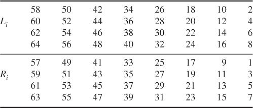
Table 4.5 E bit-selection table
The expansion symbol E of ![]() denotes a function which takes the 32-bit
denotes a function which takes the 32-bit ![]() as input and produces the 48-bit
as input and produces the 48-bit ![]() as output. The purpose of this operation is twofold—to make the output the same size as the key for the XOR and to provide a longer result that is compressed during the S-box substitution operation.
as output. The purpose of this operation is twofold—to make the output the same size as the key for the XOR and to provide a longer result that is compressed during the S-box substitution operation.
After the compressed key ![]() is XORed with the expanded block
is XORed with the expanded block ![]() such that
such that ![]() for
for ![]() , this 48-bit
, this 48-bit ![]() moves to substitution operations that are performed by eight
moves to substitution operations that are performed by eight ![]() -boxes. The 48-bit
-boxes. The 48-bit ![]() is divided into eight 6-bit blocks. Each 6-bit block is operated on by a separate
is divided into eight 6-bit blocks. Each 6-bit block is operated on by a separate ![]() -box, as shown in Figure 4.2. Each
-box, as shown in Figure 4.2. Each ![]() -box is a table of 4 rows and 16 columns as shown in Table 4.6. This 48-bit input
-box is a table of 4 rows and 16 columns as shown in Table 4.6. This 48-bit input ![]() to the S-boxes are passed through a nonlinear S-box transformation to produce the 32-bit output.
to the S-boxes are passed through a nonlinear S-box transformation to produce the 32-bit output.
Table 4.6 S-boxes
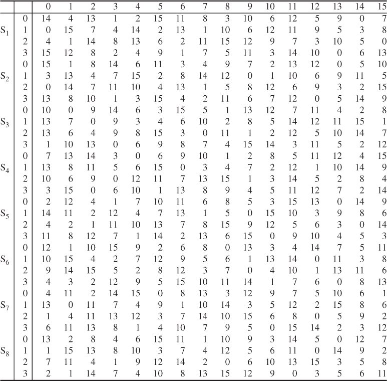
If each ![]() denotes a matrix box defined in Table 4.6 and A denotes an input block of 6 bits, then
denotes a matrix box defined in Table 4.6 and A denotes an input block of 6 bits, then ![]() (A) is defined as follows: the first and last bits of A represent the row number of the matrix
(A) is defined as follows: the first and last bits of A represent the row number of the matrix ![]() , while the middle 4 bits of A represent a column number of
, while the middle 4 bits of A represent a column number of ![]() in the range from 0 to 15.
in the range from 0 to 15.
For example, for the input (101110) to ![]() -box, denoted as
-box, denoted as ![]() (0111), the first and last bits combine to form 10, which corresponds to the row 2 (actually third row) of
(0111), the first and last bits combine to form 10, which corresponds to the row 2 (actually third row) of ![]() . The middle 4 bits combine to form 0111, which corresponds to the column 7 (actually the eighth column) of the same
. The middle 4 bits combine to form 0111, which corresponds to the column 7 (actually the eighth column) of the same ![]() -box. Thus, the entry under row 2, column 7 of
-box. Thus, the entry under row 2, column 7 of ![]() -box is computed as:
-box is computed as:
![]()
Thus, the value of 1000 is substituted for 101110; that is, the 4-bit output 1000 from ![]() is substituted for the 6-bit input 101110 to
is substituted for the 6-bit input 101110 to ![]() . Eight 4-bit blocks are the S-box output resulting from the substitution phase, which recombine into a single 32-bit block
. Eight 4-bit blocks are the S-box output resulting from the substitution phase, which recombine into a single 32-bit block ![]() by concatenation. This 32-bit output
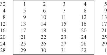
by concatenation. This 32-bit output ![]() of the S-box substitution is permuted according to Table 4.7. This permutation maps each input bit of
of the S-box substitution is permuted according to Table 4.7. This permutation maps each input bit of ![]() to an output position of P(
to an output position of P(![]() ). The output
). The output ![]() ) are obtained from the input
) are obtained from the input ![]() by taking the sixteenth bit of
by taking the sixteenth bit of ![]() as the first bit of
as the first bit of ![]() ), the seventh bit as the second bit of
), the seventh bit as the second bit of ![]() ), and so on until the twenty-fifth bit of
), and so on until the twenty-fifth bit of ![]() is taken as the thirty-second bit of
is taken as the thirty-second bit of ![]() ). Finally, the permuted result is XORed with the left half
). Finally, the permuted result is XORed with the left half ![]() of the initial permuted 64-bit block. Then the left and right halves are swapped and another round begins. The final permutation is the inverse of the initial permutation, and is described in Table 4.8 (
of the initial permuted 64-bit block. Then the left and right halves are swapped and another round begins. The final permutation is the inverse of the initial permutation, and is described in Table 4.8 (![]() ). Note here that the left and right halves are not swapped after the last round of DES. Instead, the concatenated block
). Note here that the left and right halves are not swapped after the last round of DES. Instead, the concatenated block ![]() is used as the input to the final permutation of Table 4.8 (
is used as the input to the final permutation of Table 4.8 (![]() ). Thus, the overall structure for DES algorithm is shown in Figure 4.4.
). Thus, the overall structure for DES algorithm is shown in Figure 4.4.
Table 4.7 Permutation function P

Table 4.8 Inverse of initial permutation, ![]()

Figure 4.4 Block cipher design of DES.
![]()
This 48-bit ![]() is first divided into eight 6-bit blocks and then fed into eight
is first divided into eight 6-bit blocks and then fed into eight ![]() -boxes. The output
-boxes. The output ![]() resulting from the S-box substitution phase is computed as
resulting from the S-box substitution phase is computed as ![]() .
.
![]()
Since ![]() , this gives
, this gives ![]() .
.
![]()
The substitution operations with S-boxes yields the 32-bit output ![]() , such that
, such that ![]() . Using Table 4.7, the permutation
. Using Table 4.7, the permutation ![]() becomes
becomes ![]() . Thus, the right-half output
. Thus, the right-half output ![]() after round 2 is computed as
after round 2 is computed as
![]()
The left-half output ![]() after round 2 is immediately obtained as
after round 2 is immediately obtained as
![]()
Concatenation of ![]() with
with ![]() is called the preoutput block in our 2-round cipher system. The preoutput is then subjected to the inverse permutation ofTable 4.8. Thus, the output of the DES algorithm at the end of the second round becomes the ciphertext Y:
is called the preoutput block in our 2-round cipher system. The preoutput is then subjected to the inverse permutation ofTable 4.8. Thus, the output of the DES algorithm at the end of the second round becomes the ciphertext Y:
![]()
4.1.4 DES Decryption
The decryption algorithm is exactly identical to the encryption algorithm except that the round keys are used in the reverse order. Since the encryption keys for each round are ![]() , the decryption keys for each round are
, the decryption keys for each round are ![]() . Therefore, the same algorithm works for both encryption and decryption. The DES decryption process will be explained in the following example.
. Therefore, the same algorithm works for both encryption and decryption. The DES decryption process will be explained in the following example.

Applying Table 4.5 to ![]() yields
yields ![]() .
.
![]()
This is the 48-bit input to the S-boxes.
![]()
![]()
Using Table 4.7 for permutation, we have
![]()
The preoutput block can be computed as follows:

![]()
![]()
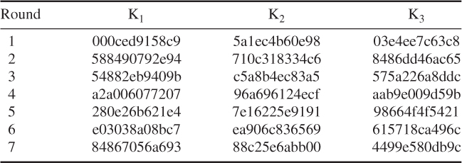
The 48-bit round keys from ![]() through
through ![]() are computed from the 56-bit key blocks through a series of permutations and left shifts, as shown below:
are computed from the 56-bit key blocks through a series of permutations and left shifts, as shown below:
| Compressed round keys | |

The 32-bit ![]() is spread out and scrambled in 48 bits, using Table 4.5, such that
is spread out and scrambled in 48 bits, using Table 4.5, such that ![]() .
.
![]()
The 32-bit output from the S-box is ![]() .
.
![]()
XORing ![]() with
with ![]() yields
yields
![]()
which is the right-half output after round 1.
Table for encryption blocks (![]() ),
), ![]()
| Li | Ri | |
| 1 | 5cd9b326 | 5d189730 |
| 2 | 5d189730 | e0e7a039 |
| 3 | e0e7a039 | 61123d5d |
| Li | Ri | |
| 4 | 61123d5d | a6f29581 |
| 5 | a6f29581 | c1fe0f05 |
| 6 | c1fe0f05 | 8e6f6798 |
| 7 | 8e6f6798 | 6bc34455 |
| 8 | 6bc34455 | ec6d1ab8 |
| 9 | ec6d1ab8 | d0d10423 |
| 10 | d0d10423 | 56a0e201 |
| 11 | 56a0e201 | b6c73726 |
| 12 | b6c73726 | 6ff2ef60 |
| 13 | 6ff2ef60 | f04bf1ad |
| 14 | f04bf1ad | f0d35530 |
| 15 | f0d35530 | 07b5cf74 |
| 16 | 07b5cf74 | 09ef5b69 |
![]()
Expansion of ![]() :
: ![]()
![]()
S-box output: ![]()
![]()
Since ![]() , the right-half output
, the right-half output ![]() is
is ![]() .
.
| Table for decryption blocks ( |
||
| 15 | f0d35530 | 07b5cf74 |
| 14 | f04bf1ad | f0d35530 |
| 13 | 6ff2ef60 | f04bf1ad |
| 12 | b6c73726 | 6ff2ef60 |
| 11 | 56a0e201 | b6c73726 |
| 10 | d0b10423 | 56a0e201 |
| 9 | ec6d1ab8 | d0b10423 |
| 8 | 6bc34499 | ec6d1ab8 |
| 7 | 8e6f6798 | 6bc34499 |
| 6 | c1fe0f05 | 8e6f6798 |
| 5 | a6f29581 | c1fe0f05 |
| 4 | 61125d5d | a6f29581 |
| 3 | e0e7a039 | 61125d5d |
| 2 | 5d189730 | e0e7a039 |
| 1 | 5cd9b326 | 5d189730 |
| 0 | 4713b8f4 | 5cd9b326 |
4.1.5 Triple DES
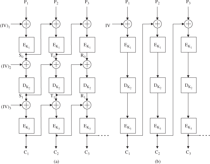
Triple DES is popular in Internet-based applications, including PGP and S/MIME. The possible vulnerability of DES to a brute-force attack brings us to find an alternative algorithm. Triple DES is a widely accepted approach which uses multiple encryption with DES and multiple keys, as shown in Figure 4.5. The three-key triple DES is the preferred alternative, whose effective key length is 168 bits.
Figure 4.5 Triple DES (a) encryption and (b) decryption.

Triple DES with two keys (![]() , K2) is a relatively popular alternative to DES. But triple DES with three keys (K1, K2, K3) is preferred, as it results in a great increase in cryptographic strength. However, this alternative raises the cost of the known-plaintext attack to 2
, K2) is a relatively popular alternative to DES. But triple DES with three keys (K1, K2, K3) is preferred, as it results in a great increase in cryptographic strength. However, this alternative raises the cost of the known-plaintext attack to 2![]() , which is beyond what is practical.
, which is beyond what is practical.
Referring to Figure 4.5, the ciphertext C is produced as
![]()
The sender encrypts with the first key K1, then decrypts with the second key K2, and finally encrypts with the third key K3. Decryption requires that the keys are applied in reverse order:
![]()
The receiver decrypts with the third key K3, then encrypts with the second key K2, and finally decrypts with the first key K1. This process is sometimes known as Encrypt-Decrypt-Encrypt (EDE) mode.

and the plaintext ![]() .
.

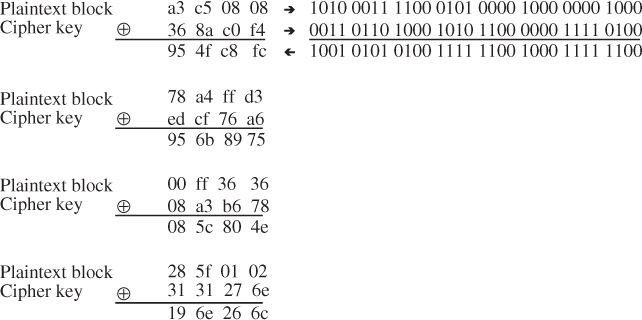
4.1.6 DES-CBC Cipher Algorithm with IV
This section describes the use of the DES cipher algorithm in Cipher Block Chaining (CBC) mode as a confidentiality mechanism within the context of the Encapsulating Security Payload (ESP). ESP provides confidentiality for IP datagrams by encrypting the payload data to be protected (Chapter 8).
DES-CBC requires an explicit Initialization Vector (IV) of 64 bits that is the same size as the block size. The IV must be a random value which prevents the generation of identical ciphertext. IV implementations for inner CBC must not use a low Hamming distance between successive IVs. The IV is XORed with the first plaintext block before it is encrypted. For successive blocks, the previous ciphertext block is XORed with the current plaintext before it is encrypted.
DES-CBC is a symmetric secret key algorithm. The key size is 64 bits, but it is commonly known as a 56-bit key. The key has 56 significant bits; the least significant bit in every byte is the parity bit.
There are several ways to specify triple DES encryption, depending on the decision which affects both security and efficiency. For using triple encryption with three different keys, there are two possible triple-encryption modes (i.e., three DES-EDE modes): inner CBC and outer CBC, as shown in Figure 4.6.
Figure 4.6 Triple DES-EDE in CBC mode. (a) Inner CBC and (b) outer CBC.
Inner CBC
This mode requires three different IVs.

Outer CBC
This mode requires one IV.

Assume that three keys K1, K2, and K3 used in this example are exactly the same keys as those given in Example 4.6. The computation of ciphertext blocks (![]() ,
, ![]() ,
, ![]() ) at each EDE stage is shown as follows:
) at each EDE stage is shown as follows:

Thus, all three ciphertext blocks (![]() ,
, ![]() ,
, ![]() ) are obtained using the outer CBC mechanism.
) are obtained using the outer CBC mechanism.
4.2 International Data Encryption Algorithm (IDEA)
In 1990, Xuejia Lai and James Massey of the Swiss Federal Institute of Technology devised a new block cipher. The original version of this block-oriented encryption algorithm was called the Proposed Encryption Standard (PES). Since then, PES has been strengthened against differential cryptographic attacks. In 1992, the revised version of PES appeared to be strong and was renamed as the International Data Encryption Algorithm (IDEA). IDEA is a block cipher that uses a 128-bit key to encrypt 64-bit data blocks.
Pretty Good Privacy (PGP) provides a privacy and authentication service that can be used for e-mail and file storage applications. PGP uses IDEA for conventional block encryption, along with RSA for public-key encryption and MD5 for hash coding. The 128-bit key length seems to be long enough to effectively prevent exhaustive key searches. The 64-bit input block size is generally recognized as sufficiently strong enough to deter statistical analysis, as experienced with DES. The ciphertext depends on the plaintext and key, which are largely involved in a complicated manner. IDEA achieves this goal by mixing three different operations. Each operation is performed on two 16-bit inputs to produce a single 16-bit output. IDEA has a structure that can be used for both encryption and decryption, like DES.
4.2.1 Subkey Generation and Assignment
The 52 subkeys are all generated from the 128-bit original key. IDEA uses fifty-two 16-bit key sub-blocks, that is, six subkeys for each of the first eight rounds and four more for the ninth round of output transformation.
The 128-bit encryption key is divided into eight 16-bit subkeys. The first eight subkeys, labeled ![]() ,
, ![]() ,
, ![]()
![]() are taken directly from the key, with
are taken directly from the key, with ![]() being equal to the first 16 bits,
being equal to the first 16 bits, ![]() to the next 16 bits, and so on. The first eight subkeys for the algorithm are assigned such that the six subkeys are for the first round, and the first two for the second round. After that, the key is circularly shifted 25 bits to the left and again divided into eight subkeys. This procedure is repeated until all 52 subkeys have been generated. Since each round uses the 96-bit subkey (
to the next 16 bits, and so on. The first eight subkeys for the algorithm are assigned such that the six subkeys are for the first round, and the first two for the second round. After that, the key is circularly shifted 25 bits to the left and again divided into eight subkeys. This procedure is repeated until all 52 subkeys have been generated. Since each round uses the 96-bit subkey (![]() ) and the 128-bit subkey (
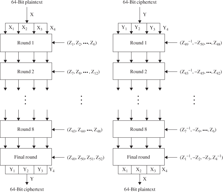
) and the 128-bit subkey (![]() ) is extracted with each 25-bit rotation of the key, there is no way to expect a simple shift relationship between the subkeys of one round and that of another. Thus, this key schedule provides an effective technique for varying the key bits used for subkeys in the eight rounds. Figure 4.7 illustrates the subkey generation scheme for making use of IDEA encryption/decryption.
) is extracted with each 25-bit rotation of the key, there is no way to expect a simple shift relationship between the subkeys of one round and that of another. Thus, this key schedule provides an effective technique for varying the key bits used for subkeys in the eight rounds. Figure 4.7 illustrates the subkey generation scheme for making use of IDEA encryption/decryption.
Figure 4.7 IDEA encryption/decryption block diagrams.
If the original 128-bit key is labeled as Z(1, 2, ![]() 128), then the entire subkey blocks of the eight rounds have the following bit assignments (Table 4.9).
128), then the entire subkey blocks of the eight rounds have the following bit assignments (Table 4.9).
Table 4.9 Generation of IDEA 16-bit subkeys
| Round 1 | |
| Round 2 | |
| Round 3 | |
| Round 4 | |
| Round 5 | |
| Round 6 | |
| Round 7 | |
| Round 8 | |
| Round 9 (final transformation stage) | |
Only six 16-bit subkeys are needed in each round, whereas the final transformation uses four 16-bit subkeys. But eight subkeys are extracted from the 128-bit key with the left shift of 25 bits. That is why the first subkey of each round is not in order, as shown in Table 4.9.
![]()
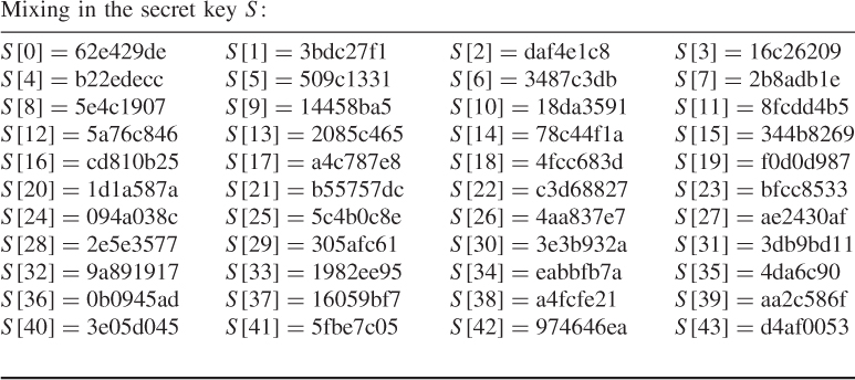
The 52 16-bit subkey blocks are computed from the given key Z as follows: for the first round, the first eight subkeys are taken directly from Z. After that, the key Z is circularly shifted 25 bits to the left and again divided into eight 16-bit subkeys. This shift-divide procedure is repeated until all 52 subkeys are generated, as shown in Table 4.9. The IDEA encryption key is computed as shown in Table 4.10.
Table 4.10 Subkeys for encryption
4.2.2 IDEA Encryption
The overall scheme for IDEA encryption is illustrated in Figure 4.8. As with all block ciphers, there are two inputs to the encryption function, that is, the plaintext block and encryption key. IDEA is unlike DES (which relies mainly on the XOR and on nonlinear S-boxes). In IDEA, the plaintext is 64 bits in length and the key size is 128 bits long. The design methodology behind IDEA is based on mixing three different operations:
IDEA utilizes both confusion and diffusion by using these three different operations. For example, for the additive inverse modulo ![]() , where the notation
, where the notation ![]() denotes the additive inverse, and for the multiplicative inverse modulo
denotes the additive inverse, and for the multiplicative inverse modulo ![]() , where the notation
, where the notation ![]() denotes the multiplicative inverse.
denotes the multiplicative inverse.
Figure 4.8 IDEA encryption scheme.

In Figure 4.8, IDEA consists of eight rounds followed by a final output transformation. The 64-bit input block is divided into four 16-bit sub-blocks, labeled ![]() , and
, and ![]() . These four sub-blocks become the input to the first round of IDEA. The subkey generator generates a total of 52 subkey blocks that are all generated from the original 128-bit encryption key. Each subkey block consists of 16 bits. The first round makes use of six 16-bit subkeys (
. These four sub-blocks become the input to the first round of IDEA. The subkey generator generates a total of 52 subkey blocks that are all generated from the original 128-bit encryption key. Each subkey block consists of 16 bits. The first round makes use of six 16-bit subkeys (![]() ), whereas the final output transformation uses four 16-bit subkeys (
), whereas the final output transformation uses four 16-bit subkeys (![]() ). The final transformation stage also produces four 16-bit blocks, which are concatenated to form the 64-bit ciphertext. In each round of Figure 4.8, the four 16-bit sub-blocks are XORed, added, and multiplied with one another and with six 16-bit key sub-blocks. Between each round, the second and third sub-blocks are interchanged. This swapping operation increases the mixing of the bits being processed and makes the IDEA more resistant to differential cryptanalysis.
). The final transformation stage also produces four 16-bit blocks, which are concatenated to form the 64-bit ciphertext. In each round of Figure 4.8, the four 16-bit sub-blocks are XORed, added, and multiplied with one another and with six 16-bit key sub-blocks. Between each round, the second and third sub-blocks are interchanged. This swapping operation increases the mixing of the bits being processed and makes the IDEA more resistant to differential cryptanalysis.
In each round, the sequential operations will be taken into the following steps:
The output of each round is the four sub-blocks that result from steps 11–14. The two inner blocks (12) and (13) are interchanged before being applied to the next-round input. The final output transformation after the eighth round will involve the following steps:
where ![]() , represents the output of the eighth round. As you see, the final ninth stage requires only four subkeys,
, represents the output of the eighth round. As you see, the final ninth stage requires only four subkeys, ![]() ,
, ![]() ,
, ![]() , and
, and ![]() , compared to six subkeys for each of the first eight rounds. Note also that no swap is required for the two inner blocks at the output transformation stage.
, compared to six subkeys for each of the first eight rounds. Note also that no swap is required for the two inner blocks at the output transformation stage.
4.1 ![]()
In the IDEA encryption, the plaintext is 64 bits in length and the encryption key consists of the 52 subkeys as computed in Example 4.8.
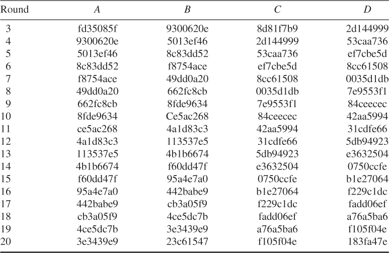
Table 4.11 Ciphertext computation through IDEA encryption rounds
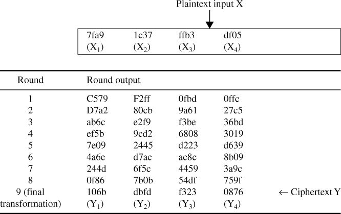
The ciphertext Y represents the output of the final transformation stage:
![]()
4.2.3 IDEA Decryption
IDEA decryption is exactly the same as the encryption process, except that the key sub-blocks are reversed and a different selection of subkeys is used. The decryption subkeys are either the additive or multiplicative inverse of the encryption subkeys. The decryption key sub-blocks are derived from the encryption key sub-blocks shown in Table 4.12.
Table 4.12 IDEA encryption and decryption subkeys
| Round | Encryption subkeys | Decryption subkeys |
| 1 | ||
| 2 | ||
| 3 | ||
| 4 | ||
| 5 | ||
| 6 | ||
| 7 | ||
| 8 | ||
| 9 |
Looking at the decryption key sub-blocks in Table 4.12, we see that the first four decryption subkeys at round ![]() are derived from the first four subkeys at encryption round (
are derived from the first four subkeys at encryption round (![]() ), where the output transformation stage is counted as round 9. For example, the first four decryption subkeys at round 2 are derived from the first four encryption subkeys of round 8, as shown in Table 4.13.
), where the output transformation stage is counted as round 9. For example, the first four decryption subkeys at round 2 are derived from the first four encryption subkeys of round 8, as shown in Table 4.13.
Table 4.13 Decryption subkeys derived from encryption subkeys

Note that the first and fourth decryption subkeys are equal to the multiplicative inverse modulo ![]() of the corresponding first and fourth encryption subkeys. For rounds 2–8, the second and third decryption subkeys are equal to the additive inverse modulo 2
of the corresponding first and fourth encryption subkeys. For rounds 2–8, the second and third decryption subkeys are equal to the additive inverse modulo 2![]() of the corresponding subkeys' third and second encryption subkeys. For rounds 1 and 9, the second and third decryption subkeys are equal to the additive inverse modulo 2
of the corresponding subkeys' third and second encryption subkeys. For rounds 1 and 9, the second and third decryption subkeys are equal to the additive inverse modulo 2![]() of the corresponding second and third encryption subkeys. Note also that, for the first eight rounds, the last two subkeys of decryption round
of the corresponding second and third encryption subkeys. Note also that, for the first eight rounds, the last two subkeys of decryption round ![]() are equal to the last two subkeys of encryption round (
are equal to the last two subkeys of encryption round (![]() ) (Table 4.12).
) (Table 4.12).
Table 4.14 Subkey blocks for decryption
Figure 4.9 IDEA decryption scheme.

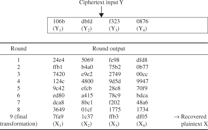
Table 4.15 Plaintext computation through IDEA decryption steps
4.3 RC5 Algorithm
The RC5 encryption algorithm was designed by Ronald Rivest of the Massachusetts Institute of Technology (MIT) and it first appeared in December 1994. RSA Data Security, Inc. estimates that RC5 and its successor, RC6, are strong candidates for potential successors to DES. RC5 analysis (RSA Laboratories) is still in progress and is periodically updated to reflect any additional findings.
4.3.1 Description of RC5
RC5 is a symmetric block cipher designed to be suitable for both software and hardware implementation. It is a parameterized algorithm, with a variable block size, a variable number of rounds, and a variable-length key. This provides the opportunity for great flexibility in both performance characteristics and the level of security.
A particular RC5 algorithm is designated as RC5-![]() . The number of bits in a word,
. The number of bits in a word, ![]() , is a parameter of RC5. Different choices of this parameter result in different RC5 algorithms. RC5 is iterative in structure, with a variable number of rounds. The number of rounds,
, is a parameter of RC5. Different choices of this parameter result in different RC5 algorithms. RC5 is iterative in structure, with a variable number of rounds. The number of rounds, ![]() , is the second parameter of RC5. RC5 uses a variable-length secret key. The key length
, is the second parameter of RC5. RC5 uses a variable-length secret key. The key length ![]() (in bytes) is the third parameter of RC5. These parameters are summarized as follows:
(in bytes) is the third parameter of RC5. These parameters are summarized as follows:
RC5 consists of three components: a key-expansion algorithm, an encryption algorithm, and a decryption algorithm. These algorithms use the following three primitive operations:
One design feature of RC5 is its simplicity, which makes RC5 easy to implement. Another feature of RC5 is its heavy use of data-dependent rotations in encryption; this feature is very useful in preventing both differential and linear cryptanalysis.
4.3.2 Key Expansion
The key-expansion algorithm expands the user's key ![]() to fill the expanded key table
to fill the expanded key table ![]() , so that
, so that ![]() resembles an array of
resembles an array of ![]() random binary words determined by
random binary words determined by ![]() . It uses two word-size magic constants
. It uses two word-size magic constants ![]() and
and ![]() defined for arbitrary
defined for arbitrary ![]() as shown below:
as shown below:

where
First algorithmic step of key expansion
This step is to copy the secret key ![]() [0, 1,
[0, 1, ![]()
![]() ] into an array
] into an array ![]() [0, 1,
[0, 1, ![]()
![]() ] of
] of ![]() words, where
words, where ![]() /8 is the number of bytes/word.
/8 is the number of bytes/word.
This first step will be achieved by the following pseudocode operation: for ![]() down to 0 do
down to 0 do ![]() , where all bytes are unsigned and the array
, where all bytes are unsigned and the array ![]() is initially zeroes.
is initially zeroes.
Second algorithmic step of key expansion
This step is to initialize array ![]() to a particular fixed pseudorandom bit pattern, using an arithmetic progression modulo 2
to a particular fixed pseudorandom bit pattern, using an arithmetic progression modulo 2![]() determined by two constants
determined by two constants ![]() and
and ![]() .
.

Third algorithmic step of key expansion
This step is to mix in the user's secret key in three passes over the arrays ![]() and
and ![]() . More precisely, due to the potentially different sizes of
. More precisely, due to the potentially different sizes of ![]() and
and ![]() , the larger array is processed three times and the other array will be handled more after.
, the larger array is processed three times and the other array will be handled more after.
![]()
do 3![]() max (
max (![]() times:
times:
Note that with the key-expansion function it is not so easy to determine ![]() from
from ![]() due to the one-wayness.
due to the one-wayness.
The plaintext and the user's secret key are given as follows:
![]()
1. Key expansion
Thus, converting the secret key from bytes to words (*) yields:

When the iterative processes continue up to ![]() , we can obtain the expanded key table
, we can obtain the expanded key table ![]() as shown below:
as shown below:


This is the first group expanded key table ![]() resulted from iterative process over
resulted from iterative process over ![]() .
.
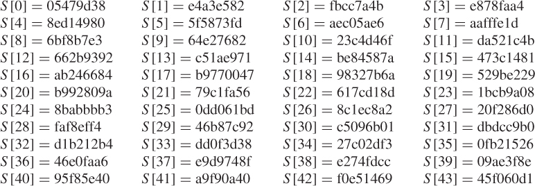
Table 4.16 Expanded key table ![]() resulted from groupwise iterative operation over
resulted from groupwise iterative operation over ![]()
4.3.3 Encryption
The input block to RC5 consists of two ![]() -bit words given in two registers,
-bit words given in two registers, ![]() and
and ![]() . The output is also placed in the registers
. The output is also placed in the registers ![]() and
and ![]() . Recall that RC5 uses an expanded key table,
. Recall that RC5 uses an expanded key table, ![]() , consisting of
, consisting of ![]() words. The key-expansion algorithm initializes
words. The key-expansion algorithm initializes ![]() from the user's given secret key parameter
from the user's given secret key parameter![]() . However, the
. However, the ![]() table in RC5 encryption is not like an S-box used by DES. The encryption algorithm is given in the pseudocode as shown below:
table in RC5 encryption is not like an S-box used by DES. The encryption algorithm is given in the pseudocode as shown below:
![]()
for ![]() to
to ![]() do
do
![]()
The output is in the registers ![]() and
and ![]() .
.
![]()
To encrypt the 64-bit input block X, the following steps will be taken:
- Store the plaintext in two 32-bit registers, A and B.
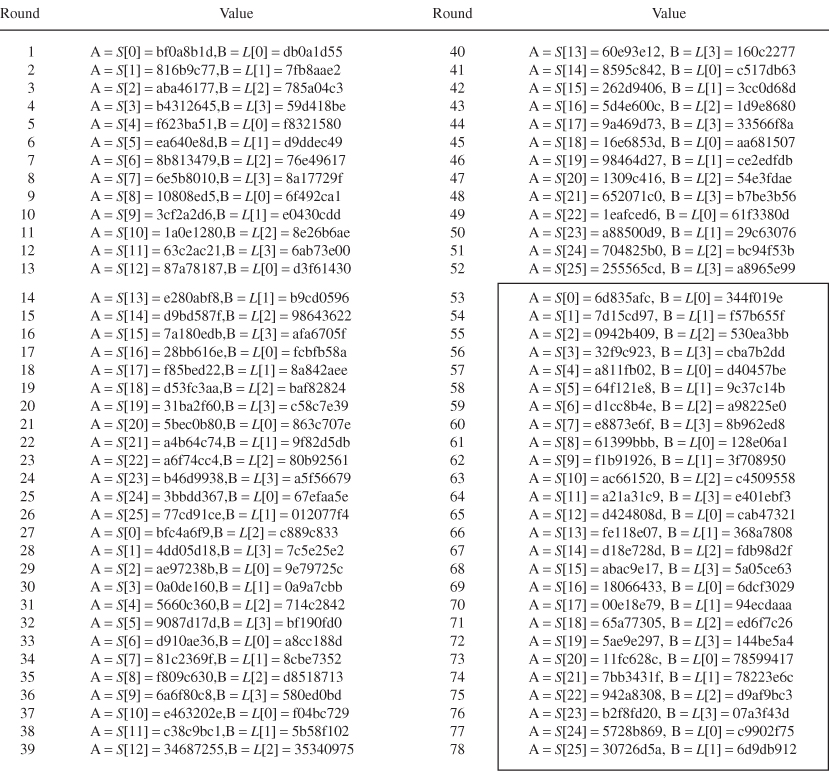
- Choose the third group expanded key table S[0], S[1], …, S[25] over 54 ≤ r ≤ 77 as shown in Table 4.16.
- Compute the ciphertext using the RC5 encryption algorithm according to Figure 4.10.
Figure 4.10 RC5 encryption algorithm.

![]()
![]()
![]()
![]()
On the other hand, B-routine computation becomes:
![]()
![]()
![]()
Finally,

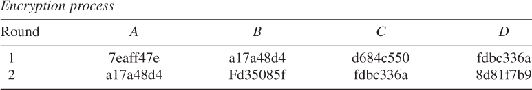
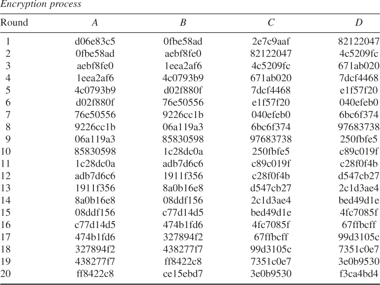
We have computed the first two rounds 0 and 1. Repeated computation up to round 12 will be resulted in the following encryption process table.
Encryption process
| Round | A | B |
| 0 | 5c5f001d | eaa518ac |
| 1 | aacdcf78 | 073A31fa |
| 2 | b2c9dafc | d0506098 |
| 3 | 362f2508 | 67cccf55 |
| 4 | ace3d838 | 5f84483d |
| 5 | 6ad30720 | d77180e6 |
| 6 | 3cc6723c | accd0d34 |
| 7 | c2177344 | 9954851d |
| 8 | 436ee2fe | f7702871 |
| 9 | fac6db42 | 91c5af63 |
| 10 | 6a180397 | f63131f5 |
| 11 | e07e082e | 816fc2b3 |
| 12 | ac13c0f7 | 52892b5b |
Ciphertext = ac13c0f7 52892b5b.
4.3.4 Decryption
RC5 decryption is given in the pseudocode as shown below.
For ![]() down to 1 do
down to 1 do

The decryption routine is easily derived from the encryption routine. The RC5 encryption/decryption algorithms are illustrated as shown in Figures 4.10 and 4.11, respectively.
Figure 4.11 RC5 decryption algorithm.

![]()
- B-routine computation:
![]()
(Refer to third group expended key in Table 4.16)
![]()
Convert A = 0xac13c0f7 to decimal number such that
![]()
![]()
Thus, the B-routine computation for round 12 is completed.
- A-routine computation
![]()
Convert the hexadecimal S[24] to its binary sequence and then take the 2's complement of its binary sequence to obtain the additive inverse –S[24] as follows.
![]()
Convert Hexadecimal to Decimal:
![]()
![]()
This result shows the end of A-routine computation for Round 12.
![]()
![]()
![]()
where ![]() (decimal)
(decimal)

![]()
![]()
This is the result of A-routine computation for Round 11.
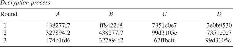
Decryption process
| Round | A | B |
| 12 | e07e082e | 816fc2b3 |
| 11 | 6a180397 | f63131f5 |
| 10 | fac6db42 | 91c5af63 |
| 9 | 436ee2fe | f7702871 |
| 8 | c2177344 | 9954851d |
| 7 | 3cc6723c | accd0d34 |
| 6 | 6ad30720 | d77180e6 |
| 5 | ace3d838 | 5f84483d |
| 4 | 362f2508 | 67cccf55 |
| 3 | b2c9dafc | d0506098 |
| 2 | aacdcf78 | 073a31fa |
| 1 | 5c5f001d | eaa518ac |
Deciphered plaintext = eedba521 6d8f4b15.

Encryption
| Round | A | B |
| 0 | bd7a3978 | 08b9f366 |
| 1 | a8c06bd8 | 85ed284f |
| 2 | b4bf3585 | 90fe1e28 |
| 3 | eff03eac | 28a2421b |
| 4 | cd58becc | 5e05cc06 |
| 5 | 722d5b91 | 604e64a0 |
| 6 | 08e31821 | 5f3a0f83 |
| 7 | f944d070 | 02ca706b |
| 8 | ba17322a | f7542d09 |
| 9 | be78e241 | ae7a1379 |
| 10 | ae30c3c2 | 43413d61 |
| 11 | d3c39d63 | 51b85bc0 |
| 12 | 244fd451 | ae140ae0 |
| 13 | 5e9c7411 | 02157ae0 |
| 14 | 44a9b768 | d566f0c2 |
| 15 | 485ad502 | e6f6c625 |
| 16 | 548854fc | 8a20fd1a |
Ciphertext = 548854fc 8a20fd1a.
Decryption
| Round | A | B |
| 16 | 485ad502 | e6f6c625 |
| 15 | 44a9b768 | d566f0c2 |
| 14 | 5e9c7411 | 02157ae0 |
| 13 | 244fd451 | ae140ae0 |
| 12 | d3c39d63 | 51b85bc0 |
| 11 | ae30c3c2 | 43413d61 |
| 10 | be78e241 | ae7a1379 |
| 9 | ba17332a | f7542d09 |
| 8 | f944d070 | 02ca706b |
| 7 | 08e31821 | 5f3a0f83 |
| 6 | 722d5b91 | 604e64a0 |
| 5 | cd58becc | 5e05cc06 |
| 4 | eff03eac | 28a2421b |
| 3 | b4bf3585 | 90fe1e28 |
| 2 | a8c06bd8 | 85ed284f |
| 1 | bd7a3978 | 08b9f366 |
| 0 | eedba521 | 6d8f4615 |
Plaintext (deciphered text) = eedba52 6d8f4b15.
4.4 RC6 Algorithm
RC6 is an improvement to RC5, designed to meet the requirements of increased security and better performance. Like RC5, which was proposed in 1995, RC6 makes use of data-dependent rotations. One new feature of RC6 is the use of four working registers instead of two. While RC5 is a fast block cipher, extending it to act on 128-bit blocks using two 64-bit working registers, RC6 is modified its design to use four 32-bit registers rather than two 64-bit registers. This has the advantage that it can be done two rotations per round rather than the one found in a half-round of RC5.
4.4.1 Description of RC6
Like RC5, RC6 is a fully parameterized family of encryption algorithms. A version of RC6 is also specified as RC6-![]() where the word size is
where the word size is ![]() bits, encryption consists of a number of rounds
bits, encryption consists of a number of rounds ![]() , and
, and ![]() denotes the encryption key length in bytes.
denotes the encryption key length in bytes.
RC6 was submitted to NIST for consideration as the new AES. Since the AES submission is targeted at ![]() and
and ![]() , the parameter values specified as RC6-
, the parameter values specified as RC6-![]() are used as shorthand to refer to such versions. For all variants, RC6-
are used as shorthand to refer to such versions. For all variants, RC6-![]() operates on four
operates on four ![]() -bit words using the following six basic operations:
-bit words using the following six basic operations:
RC6 exploits data-dependent operations such that 32-bit integer multiplication is efficiently implemented on most processors. Integer multiplication is a very effective diffusion and is used in RC6 to compute rotation amounts so that these amounts are dependent on all of the bits of another register. As a result, RC6 has much faster diffusion than RC5.
4.4.2 Key Schedule
The key schedule of RC6-![]() is practically identical to that of RC5-
is practically identical to that of RC5-![]() . In fact, the only difference is that in RC6-
. In fact, the only difference is that in RC6-![]() , more words are derived from the user-supplied key for use during encryption and decryption.
, more words are derived from the user-supplied key for use during encryption and decryption.
The user supplies a key of ![]() bytes, where
bytes, where ![]() . Sufficient zero bytes are appended to give a key length equal to a nonzero integral number of words; these key bytes are then loaded into an array of c
. Sufficient zero bytes are appended to give a key length equal to a nonzero integral number of words; these key bytes are then loaded into an array of c ![]() -bit words
-bit words ![]() [0],
[0], ![]() [1],
[1], ![]()
![]() . The number of
. The number of ![]() -bit words generated for additive round keys is
-bit words generated for additive round keys is ![]() , and these are stored in the array
, and these are stored in the array ![]() [0, 1,
[0, 1, ![]()
![]() ].
].
The key schedule algorithm is as shown below.
Key Schedule for RC6-
Input: User-supplied ![]() byte key preloaded into the
byte key preloaded into the ![]() -word array
-word array ![]() [0, 1,
[0, 1, ![]()
![]() ]
]
Number of rounds, ![]()
Output: ![]() -bit round keys
-bit round keys ![]() [0, 1,
[0, 1, ![]()
![]() ]
]
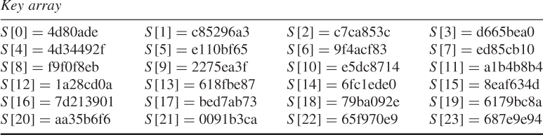
Key expansion:
Definition of the magic constants
where
Converting the secret key from bytes to words
for ![]() down to 0 do
down to 0 do
![]()
Initializing the array 
Mixing in the secret key 

4.4.3 Encryption
RC6 encryption works with four ![]() -bit registers
-bit registers ![]() ,
, ![]() ,
, ![]() , and
, and ![]() which contain the initial input plaintext. The first byte of plaintext is placed in the least significant byte of
which contain the initial input plaintext. The first byte of plaintext is placed in the least significant byte of ![]() . The last byte of plaintext is placed into the most significant byte of
. The last byte of plaintext is placed into the most significant byte of ![]() . The arrangement of
. The arrangement of ![]() is like that of the paralleled assignment of values (bytes) on the right to the registers on the left, as shown in Figure 4.12.
is like that of the paralleled assignment of values (bytes) on the right to the registers on the left, as shown in Figure 4.12.
Figure 4.12 RC6-![]() encryption scheme.
encryption scheme.

The RC6 encryption algorithm is shown below:
Encryption with RC6-
Input: Plaintext stored in four ![]() -bit input registers
-bit input registers ![]()
Number of rounds, ![]()
![]() -bit round keys
-bit round keys ![]() [0, 1,
[0, 1, ![]()
![]() ]
]
Output: Ciphertext stored in ![]()

![]()
![]()
![]()
Final value in each register:
![]()
Thus, the ciphertext is computed as:
![]()
4.4.4 Decryption
RC6 decryption works with four ![]() -bit registers
-bit registers ![]() which contain the initial output ciphertext at the end of encryption. The first byte of ciphertext is placed into the least significant byte of
which contain the initial output ciphertext at the end of encryption. The first byte of ciphertext is placed into the least significant byte of ![]() . The last byte of ciphertext is placed into the most significant byte of
. The last byte of ciphertext is placed into the most significant byte of ![]() .
.
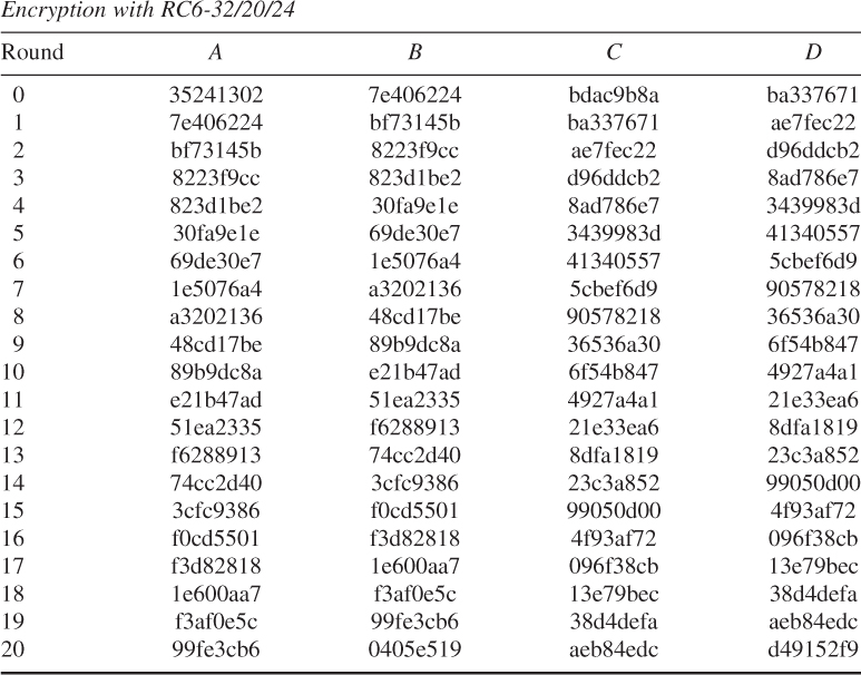
The RC6 decryption algorithm is illustrated as shown below:
Decryption with RC6-![]()
Input: Ciphertext stored in four ![]() -bit input registers
-bit input registers ![]()
Number of rounds, ![]()
![]() -bit round keys
-bit round keys ![]() [0, 1,
[0, 1, ![]()
![]() ]
]
Output: Plaintext stored in ![]()
The decryption of RC6 is depicted as shown in Figure 4.13.
Figure 4.13 RC6-![]() decryption scheme.
decryption scheme.

![]()


Final value in each register:
![]()
Thus, the recovered plaintext is computed as:
![]()
![]()
Converting the secret key from bytes to words:
![]()
![]()
![]()
Thus, the ciphertext is computed as: ![]()
![]()
Decryption:
![]()

The user supplies a key of ![]() bytes, where
bytes, where ![]() . From this key,
. From this key, ![]() words are derived and stored in the array
words are derived and stored in the array ![]() . This array is used in both encryption and decryption.
. This array is used in both encryption and decryption.
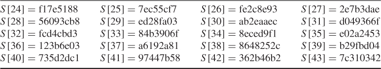
RC6 works with four 32-bit registers A, B, C, and D which contain the initial input plaintext as well as the output ciphertext at the end of encryption. Both encryption and decryption using RC6-32/20/24 are processed as shown below.
![]()
Thus, the output ciphertext at the end of encryption is:
![]()

Thus, the final decrypted plaintext is:
![]()
4.5 AES (Rijndael) Algorithm
The AES specified the Rijndael algorithm which is an FIFS-approved cryptographic algorithm developed by Daemen and Rijmen as an AES candidate algorithm in 1999. The Rijndael algorithm is a symmetric block cipher that can process data blocks of 128 bits using cryptographic keys of 128, 192, and 256 bits.
In this section, we will cover the algorithm specification such as the key-expansion routine, encryption by cipher, and decryption by inverse cipher.
4.5.1 Notational Conventions
- The cipher key for the Rijndael algorithm is a sequence of 128, 196, or 256 bits such that the index attached to a bit falls in between the range
 , or
, or  , respectively.
 - All byte values of the AES Rijndael algorithm are presented by a vector notation (
 ) which corresponds to a polynomial representation as:
 For example,
 .
. - If there is an additional bit
 to the left of an 8-bit byte, it will appear immediately to the left of the left bracket such as
  .
Arrays of bytes,
.
Arrays of bytes, , are defined from the 128-bit input sequence,
  ,
,  ,
,  ,
, 
 ,
,  , as follows:
where
 denotes
  for
for  .
.In general, the pattern extended to longer sequence like 192- and 256-bit keys is expressed as:

- The AES algorithm's operations are internally performed on a two-dimensional array of bytes called the state. The state consists of four rows of bytes. The state array
 has a row number
  , and a column number
  , where Nb
bytes are the block length divided by 32.
The input-byte array ( ,
,  ,
, 
 ) at the cipher is copied into the state array according to the following scheme:
and at the Inverse Cipher, the state is copied into the output array as follows:

An individual byte of the state is referred to as either
 or
or  . The cipher and Inverse Cipher operations are conducted on the state array as illustrated in Figure 4.14.
Figure 4.14 State array input and output.

For example, if
 and
and  , then
  ; if
; if  and
and  , then
  .The 4 bytes in each column of the state form a 32-bit word, where the row number
 provides an index for the 4 bytes within each word, and the column number
  provides an index representing the column in this array.
4.5.2 Mathematical Operations
Finite field elements (all bytes in the AES algorithm) can be added and multiplied. The basic mathematical operations will be introduced in the following.
Addition
The addition of two elements in a finite field is achieved by XORing the coefficients for the corresponding powers in the polynomials for two elements. For example,
Multiplication
The polynomial multiplication in ![]() corresponds to the multiplication of polynomial modulo
corresponds to the multiplication of polynomial modulo ![]() that an irreducible (or primitive) polynomial of degree 8 for the AES algorithm:
that an irreducible (or primitive) polynomial of degree 8 for the AES algorithm:
![]()


![]()
The element ![]() is called the multiplicative identity. For any polynomial
is called the multiplicative identity. For any polynomial ![]() of degree less than 8, the multiplicative inverse of
of degree less than 8, the multiplicative inverse of ![]() , denoted by
, denoted by ![]() , can be found by using the extended euclidean algorithm such that
, can be found by using the extended euclidean algorithm such that
![]()
from which ![]() mod
mod ![]() . Thus, the multiplicative inverse of
. Thus, the multiplicative inverse of ![]() becomes
becomes
![]()
The set of 256 possible byte values has the structure of the finite field ![]() by means of XOR used as both addition and multiplication.
by means of XOR used as both addition and multiplication.
Thus, it follows that

![]()
To illustrate the addition and multiplication operations, let
![]()
be a second polynomial.
Addition is performed by adding the finite field coefficients of like powers of ![]() such that
such that
![]()
This addition corresponds to an XOR between the corresponding bytes in each of the words. Multiplication is achieved as shown below:
The polynomial product ![]() is expanded and like powers are collected to give
is expanded and like powers are collected to give
where
The next step is to reduce ![]() mod (
mod (![]() ) for the AES algorithm, so that
) for the AES algorithm, so that ![]() mod
mod ![]() .
.
The modular product, ![]() , of two four-term polynomials
, of two four-term polynomials ![]() and
and ![]() , is given by
, is given by
![]()
where

Thus, ![]() in matrix form is written as:
in matrix form is written as:

The AES algorithm also defines the inverse polynomials as:

4.5.3 AES Algorithm Specification
For the AES algorithm, Nb denotes the number of 32-bit words with respect to the 128-bit block of the input, output, or state (![]() , from which
, from which ![]() ).
).
Nk represents the number of 32-bit words with respect to the cipher-key length of 128, 192, or 256 bits:
The number of rounds are 10, 12, and 14, respectively.
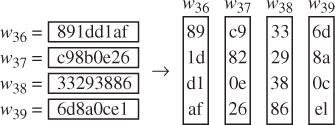
Key Expansion
The AES algorithm takes the cipher key K and performs a key-expansion routine to generate a key schedule. The key expansion generates a total of Nb(![]() ) words: an initial set of Nb words for
) words: an initial set of Nb words for ![]() and 2Nb for
and 2Nb for ![]() , 3Nb for
, 3Nb for ![]() for
for ![]() . Thus, the resulting key schedule consists of a linear array of 4-byte words
. Thus, the resulting key schedule consists of a linear array of 4-byte words ![]() ,
, ![]() ).
).
RotWord() takes a 4-byte input word [![]() ] and performs a cyclic permutation such as [
] and performs a cyclic permutation such as [![]() ].
].
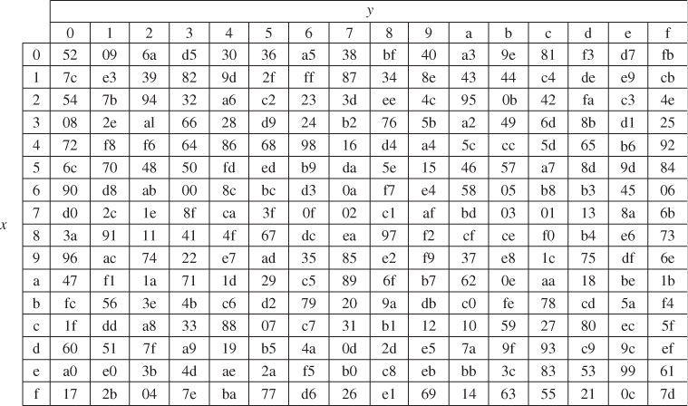
SubWord() takes a 4-byte input word and applies the S-box (Figure 4.15) to each of the 4 bytes to produce an output word.
Figure 4.15 AES S-box (FIPS Publication, 2001).

Rcon[![]() ] represents the round constant word array and contains the values given by [
] represents the round constant word array and contains the values given by [![]() ] with
] with ![]() starting
starting ![]() at 1.
at 1.

Rcon[![]() ] is a useful component for the round constant ward array in order to compute the key-expansion routine.
] is a useful component for the round constant ward array in order to compute the key-expansion routine.
Figure 4.16 Pseudocode for key expansion (FIPS Publication, 2001).

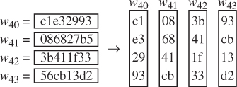
![]()
Taking each byte of RotWord(![]() [3]) at a time and applying to the S-box yields
[3]) at a time and applying to the S-box yields
![]()
Compute a round constant Rcon[![]() ]:
]:
![]()
XORing SubWord() with Rcon[1] yields
![]()
Finally, ![]() [4] is computed as:
[4] is computed as:
![]()
Continuing in this fashion, the remaining ![]() [
[![]() ],
], ![]() , can be computed as shown in Table 4.17.
, can be computed as shown in Table 4.17.
Table 4.17 AES key expansion

Cipher
The 128-bit cipher input is fed in a column-by-column manner, comprising each column with a 4-byte word. In other words, the input is copied to the state array as shown in Table 4.18.
Table 4.18 A 16-byte cipher input array

The cipher is described in the pseudocode in Figure 4.17.
Figure 4.17 Pseudocode for the cipher (FIPS Publication, 2001).

Individual transformations for the pseudocode computation consist of SubBytes(), ShiftRows(), MixColumns(), and AddRoundKey(). These transformations play a role in processing the state and are briefly described below.
SubBytes() Transformation
The SubBytes() transformation is a nonlinear byte substitution that operates independently on each byte of the state using an S-box (Figure 4.18).
Figure 4.18 SubBytes() transformation by the S-box.

For example, if ![]() , then the substitution value is determined by the intersection of the row with index 8 and the column with index f in Figure 4.15. The resulting
, then the substitution value is determined by the intersection of the row with index 8 and the column with index f in Figure 4.15. The resulting ![]() would be a value of
would be a value of ![]() .
.
ShiftRows() Transformation
In the ShiftRows(), the first row (row 0) is not shifted and the remaining rows proceed as follows:
![]()
where the shift value ![]() depends on the row number
depends on the row number ![]() as follows:
as follows:
![]()
This has the effect of shifting the leftmost bytes around into the rightmost positions over different numbers of bytes in a given row.
MixColumns() Transformation
The MixColumns() transformation operates on the state column-by-column, treating each column as a four-term polynomial over ![]() and multiplied modulo
and multiplied modulo ![]() with a fixed polynomial
with a fixed polynomial ![]() as:
as:
![]()
where ![]() ,
, ![]() is the input polynomial, and
is the input polynomial, and ![]() is the corresponding polynomial after the MixColumns() transformation.
is the corresponding polynomial after the MixColumns() transformation.
The matrix multiplication of ![]() is
is

The 4 bytes in a column after the matrix multiplication are

AddRoundKey() Transformation
In AddRoundKey() transformation, a round key is added to the state by a simple bitwise XOR. Each round key consists of Nb words from the key schedule. These Nb words are added into the columns of the state such that
![]()
where [![]() ] is the key schedule words and round is a value in the range
] is the key schedule words and round is a value in the range ![]() . The initial round key addition occurs when
. The initial round key addition occurs when ![]() , prior to the first application of the round function. The application of the AddRoundKey() transformation to the Nr rounds of the cipher occurs when
, prior to the first application of the round function. The application of the AddRoundKey() transformation to the Nr rounds of the cipher occurs when ![]() .
.

| 2a 2a 30 d4 → 2a 2a 30 d4 | |
| 84 7f 4a 9f → 7f 4a 9f 84 | |
| e8 a7 cd f7 → cd f7 e8 a7 | |
| b0 9d 28 50 → 50 b0 9d 28 |
MixColumns()


XOR with ![]() 46 5f 33,
46 5f 33, ![]() 89 29 95,
89 29 95, ![]() 2a 9f ed,
2a 9f ed, ![]() 1b b8 83
1b b8 83

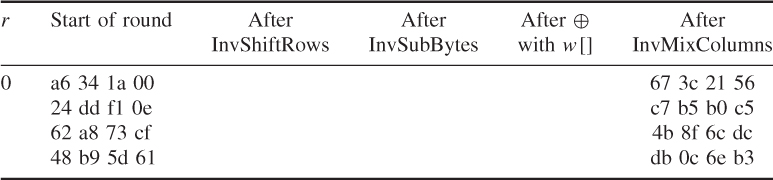
Inverse Cipher
The Cipher transformation can be implemented in reverse order to produce an Inverse Cipher for the AES algorithm. The individual transformations used in the Inverse Cipher are InvShiftRows(), InvSubBytes(), InvMixColumns(), and AddRoundKey(). These inverse transformations process the state as described in the following.
InvShiftRows() Transformation
InvShiftRows() is the inverse of the ShiftRows() transformation. The first row (Row 0) is not shifted. The bytes in the last three rows (Row 1, Row 2, Row 3) are cyclically shifted over different numbers of bytes as follows:
![]()
Specifically, the InvShiftRows() transformation proceeds as:
![]()
InvSubBytes() Transformation
InvSubBytes() is the inverse of the byte substitution transformation, in which the inverse S-box is applied to each byte of the state. The inverse S-box used in the InvSubBytes() transformation is presented in Figure 4.19.
Figure 4.19 AES algorithm Inverse S-box (FIPS Publication, 2001).
InvMixColumns() Transformation
InvMixColumns() is the inverse of the MixColumns() transformation. This transformation operates column-by-column on the state, treating each column as a four-term polynomial. The columns are considered as polynomials over GF(2![]() ) and multiplied modulo
) and multiplied modulo ![]() with a fixed polynomial
with a fixed polynomial ![]() .
.
If the inverse state ![]() is written as a matrix multiplication, then it follows:
is written as a matrix multiplication, then it follows:
![]()
where ![]() .
.
The matrix multiplication can be expressed as

This multiplication will result in 4 bytes in a column as follows:

Inverse of AddRoundKey() Transformation
AddRoundKey() is its own inverse because it only involves application of the XOR.
For decrypting ciphertext, the Inverse Cipher is described in the pseudocode shown in Figure 4.20.
Figure 4.20 Pseudocode for the Inverse Cipher (FIPS Publication, 2001).

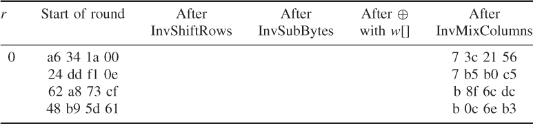
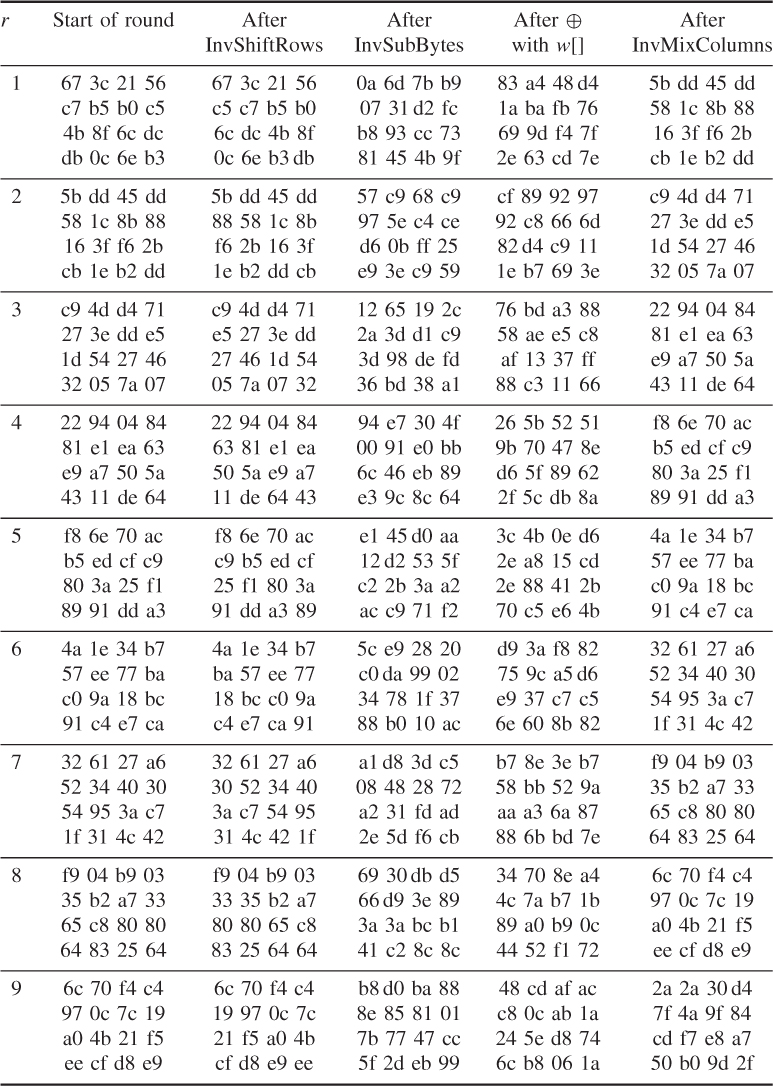
The round key values are the same as those used in Example 4.25
- AddRoundKey()
![]()

Round 1
- InvShiftRows()

The result of InvShiftRows() is
- InvSubBytes()

- AddRoundKey()

- InvMixColumns()
For ![]()

Like this, calculate ![]() ,
, ![]() , and
, and ![]() and the results are
and the results are

The remaining values can be obtained using the same way and the results are shown in the following: