
Chapter 8
Network Layer Security
TCP/IP communication can be made secure with the help of cryptography. Cryptographic methods and protocols have been designed for different purposes in securing communication on the Internet. These include the SSL and TLS for HTTP Web traffic, S/MIME and PGP for e-mail, and IPsec (Internet Protocol security) for network layer security. This chapter mainly addresses security only at the IP layer and describes various security services for traffic offered by IPsec.
8.1 IPsec Protocol
IPsec is designed to protect communication in a secure manner by using TCP/IP. The IPsec protocol is a set of security extensions developed by the IETF and it provides privacy and authentication services at the IP layer by using modern cryptography.
To protect the contents of an IP datagram, the data is transformed using encryption algorithms. There are two main transformation types that form the basics of IPsec, the Authentication Header (AH) and the Encapsulating Security Payload (ESP). Both AH and ESP are two protocols that provide connectionless integrity, data origin authentication, confidentiality, and an antireplay service. These protocols may be applied alone or in combination to provide a desired set of security services for the IP layer. They are configured in a data structure called a Security Association (SA).
The basic components of the IPsec architecture are explained in terms of the following functionalities:
- Security protocols for AH and ESP.
- SAs for policy management and traffic processing.
- Manual and automatic key management for the Internet Key Exchange (IKE), the Oakley key determination protocol, and the Internet Security Association and Key Management Protocol (ISAKMP).
- Algorithms for authentication and encryption.
The set of security services provided at the IP layer includes access control, connectionless integrity, data origin authentication, protection against replays, and confidentiality. The modularity which is designed to be algorithm independent permits selection of different sets of algorithms without affecting the other parts of the implementation.
A standard set of default algorithms is specified to facilitate interoperability in the global Internet. The use of these algorithms in conjunction with IPsec traffic protection and key management protocols is intended to permit system and application developers to deploy high-quality, Internet layer, cryptographic security technology. Thus, the suite of IPsec protocols and associated default algorithms is designed to provide high-quality security for Internet traffic.
An IPsec implementation operates in a host or a security gateway environment, affording protection to IP traffic. The protection offered is based on requirements defined by a Security Policy Database (SPD) established and maintained by a user or system administrator.
IPsec provides security services at the IP layer by enabling a system to select the required security protocols, determine the algorithms to use for the services, and put in place any cryptographic keys required to provide the requested service. IPsec can be used to protect one or more paths between a pair of hosts, between a pair of security gateways (routers or firewalls), or between a security gateway and a host.
8.1.1 IPsec Protocol Documents
This section will discuss the protocols and standards which apply to IPsec. The set of IPsec protocols is divided into seven groups as illustrated in Figure 8.1.
Figure 8.1 Document overview that defines IPsec.
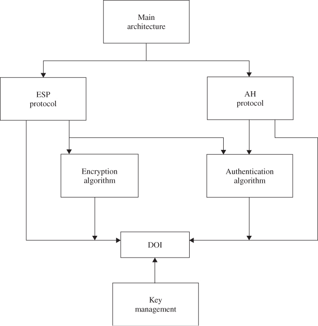
In November 1998, the Network Working Group of the IETF published RFC 2411 for IP Security Document Roadmap. This document is intended to provide guidelines for the development of collateral specifications describing the use of new encryption and authentication algorithms used with the AH protocol as well as the ESP protocol. Both these protocols are part of the IPsec architecture. The seven-group documents describing the set of IPsec protocols are explained in the following:
- Architecture. The main architecture document covers the general concepts, security requirements, definitions, and mechanisms defining IPsec technology.
- ESP. This document covers the packet format and general issues related to the use of the ESP for packet encryption and optional authentication. This protocol document also contains default values, if appropriate, and dictates some of the values in the Domain of Interpretation (DOI).
- AH. This document covers the packet format and general issues related to the use of AH for packet authentication. This document also contains default values, such as the default padding contents, and dictates some of the values in the DOI document.
- Encryption algorithm. This is a set of documents that describes how various encryption algorithms are used for ESP. Specifically,
- specification of the key sizes and strengths for each algorithm;
- any available estimates on performance of each algorithm;
- general information on how this encryption algorithm is to be used in ESP; features of this encryption algorithm to be used by ESP, including encryption and/or authentication.
- Authentication algorithm. This is a set of documents that describes how various authentication algorithms are used for AH and for the authentication option of ESP. Specifically,
- specification of operating parameters such as number of rounds and input or output block format;
- implicit and explicit padding requirements of this algorithm;
- identification of optional parameters/methods of operation;
- defaults and mandatory ranges of the algorithm;
- authentication data comparison criteria for the algorithm.
- Key management. This is a set of documents that describes key management schemes. These documents also provide certain values for the DOI. Currently, the key management represents the Oakley, ISAKMP, and Resolution protocols.
- DOI. This document contains values needed for the other documents to relate each other. These include identifiers for approved encryption and authentication algorithms, as well as operational parameters such as key lifetime.
8.1.2 Security Associations (SAs)
An SA is fundamental to IPsec. Both AH and ESP make use of SAs. Thus, the SA is a key concept that appears in both the authentication and confidentiality mechanisms for IPsec. An SA is a simplex connection between a sender and receiver that affords security services to the traffic carried on it. If both AH and ESP protection are applied to a traffic stream, then two SAs are required for two-way secure exchange.
An SA is uniquely identified by three parameters as follows:
- Security Parameter Index. (SPI) This is assigned to each SA, and each SA is identified through an SPI. A receiver uses the SPI to identify the SA for a packet. Before a sender uses IPsec to communicate with a receiver, the sender must know the index value for a particular SA. The sender thenplaces the value in the SPI field of each outgoing datagram. The SPI is carried in AH and ESP headers to enable the receiver to select the SA under which a received packet is processed. However, index values are not globally specified. A combination of the destination address and SPI is needed to identify an SA.
- IP destination address. Because, at present, unicast addresses are only allowed by IPsec SA management mechanisms, this is the address of the destination endpoint of the SA. The destination endpoint may be an end user system or a network system such as a firewall or router.
- Security protocol identifier. This identifier indicates whether the association is an AH or an ESP SA.
There are two nominal databases in a general model for processing IP traffic relative to SAs, namely, the SPD and the Security Association Database (SAD). To ensure interoperability and to provide a minimum management capability that is essential for productive use of IPsec, some external aspects for the processing standardization are required.
The SPD specifies the policies that determine the disposition of all IP traffic inbound or outbound from a host or security gateways, while the SAD contains parameters that are associated with each SA.
Security Policy Database
The SPD, which is an essential element of SA processing, specifies what services are to be offered to IP datagrams and in what fashion. The SPD is used to control the flow of all traffic (inbound and outbound) through an IPsec system, including security and key management traffic (i.e., ISAKMP). The SPD contains an ordered list of policy entries. Each policy entry is keyed by one or more selectors that define the set of all IP traffic encompassed by this entry. Each entry encompasses every indication mechanism for bypassing, discarding, or IPsec processing. The entry for IPsec processing includes SA (or SA bundle) specification, limiting the IPsec protocols, modes, and algorithms to be employed.
Security Association Database
The SAD contains parameters that are associated with each SA. Each SA has an entry in the SAD. For outbound processing, entries are pointed out by entries in the SPD. For inbound processing, each entry in the SAD is indexed by a destination IP address, IPsec protocol type, and SPI.
Transport Mode SA
There are two types of SAs to be defined: a transport mode SA and a tunnel mode SA. A transport mode provides protection primarily for upper-layer protocols, that is, a TCP packet or UDP segment or an Internet Control Message Protocol (ICMP) packet, operating directly above the IP layer. A transport mode SA is an SA between two hosts. When a host runs AH or ESP over IPv4, the payload is the data that normally follows the IP header. For IPv6, the payload is the data that normally follows both the IP header and any IPv6 extension headers. In the case of AH, AH in transport mode authenticates the IP payload and the protection is also extended to selected portions of the IP header, selected portions of IPv6 extension headers, and the selected options.
In the case of ESP, ESP in transport mode primarily encrypts and optionally authenticates the IP payload but not the IP header. A transport mode SA provides security services only for higher-layer protocols, not for the IP header or any extension headers proceeding the ESP header.
Tunnel Mode SA
Tunnel mode provides protection to the entire IP packet. A tunnel mode SA is essentially an SA applied to an IP tunnel. Whenever either end of an SA is a security gateway, the SA must be tunnel mode, as is an SA between a host and a security gateway. Note that a host must support both transport and tunnel modes, but a security gateway is required to support only the tunnel mode. If a security gateway supports transport mode, it should be used as an acting host. But in this case, the security gateway is not acting as a gateway.
When the entire inner (original) packet travels through a tunnel from one point of the IP network to another, routers along the path are unable to examine the inner IP header because the original inner packet is encapsulated. As a result, the new larger packet will have totally different source and destination addresses. When the AH and ESP fields are added to the IP packet, the entire packet plus the security field (AH or ESP) is treated as the new outer IP packet with a new outer IP header.
ESP in tunnel mode encrypts and optionally authenticates the entire inner IP packet, including the inner IP header. AH in tunnel mode authenticates the entire inner IP packet and selected portions of the outer IP header.
8.1.3 Hashed Message Authentication Code (HMAC)
A mechanism that provides a data integrity check based on a secret key is usually called the Message Authentication Code (MAC). An HMAC (Hashed Message Authentication Code) mechanism can be used with any iterative hash functions in combination with a secret key. MACs are used between two parties (e.g., client and server) that share a secret key in order to validate information transmitted between them. An MAC mechanism based on a cryptographic hash function is called HMAC. MD5 and SHA-1 are examples of such hash functions. HMAC uses a secret key for computation and verification of the message authentication values. The MAC mechanism should allow for easy replacement of the embedded hash function in case faster or more secure hash functions are found or required; that is, if it is desired to replace a given hash function in an HMAC implementation, all that is required is simply to remove the existing hash function module and replace it with the new, more secure module. HMAC can be proven as secure, provided the underlying hash function has some reasonable cryptographic strengths.
Current candidates for secure hash functions include SHA-1, MD5, and RIPEMD-160. Hash functions such as MD5 and SHA-1 are generally known to execute faster in software than symmetric block ciphers such as DES–CBC (Data Encryption Standard-Cipher Block Chaining). There has been a number of proposals for the incorporation of a secret key into an existing hash function. MD5 has been recently shown to be vulnerable to collision search attacks. Therefore, it seems that MD5 does not compromise its use within HMAC because it does not rely on a secret key. However, SHA-1 appears to be a cryptographically stronger function.
HMAC Structure
HMAC is a secret-key authentication algorithm which provides both data integrity and data origin authentication for packets sent between two parties. Its definition requires a cryptographic hash function H and a secret key K. H denotes a hash function where the message is hashed by iterating a basic compression function on data blocks. Let b denote the block length of 64 bytes or 512 bits for all hash functions such as MD5 and SHA-1. h denotes the length of hash values, that is, ![]() bytes or 128 bits for MD5 and 20 bytes or 160 bits for SHA-1. The secret key K can be of any length up to
bytes or 128 bits for MD5 and 20 bytes or 160 bits for SHA-1. The secret key K can be of any length up to ![]() bits.
bits.
To compute HMAC over the message, the HMAC equation is expressed as follows:
![]()
where
| ipad = 00110110(0x36) repeated 64 times (512 bits); |
| opad = 01011100 (0x5c) repeated 64 times (512 bits); |
| ipad is inner padding and opad is outer padding. |
The following explains the HMAC equation:
Figure 8.2 illustrates the overall operation of HMAC–MD5.
Figure 8.2 Overall operation of HMAC computation using either MD5 or SHA-1 (message length computation based on ![]() ).
).


The alternative operation for computation of either HMAC–MD5 or HMAC–SHA-1 is described in the following:
Figure 8.3 shows the alternative scheme based on these steps.
Figure 8.3 Alternative operation of HMAC computation using either MD5 or SHA-1 (message length computation based on M only).


8.2 IP Authentication Header
The IP AH is used to provide data integrity and authentication for IP packets. It also provides protection against replays. The AH provides authentication for the IP header, as well as for upper-level protocol (TCP, UDP) data. But some IP header fields may change in transit and the sender may not be able to predict the value of these fields when the packet arrives at the receiver. Thus, the protection provided to the IP header by AH is somewhat piecemeal. The AH can be used in conjunction with ESP or with the use of tunnel mode. Security services can be provided between a pair of hosts, between a pair of security gateway, or between a security gateway and a host. The ESP provides a confidentiality service. The primary difference between the authentication provided by ESP and that by AH is the extent of the coverage. ESP does not protect any IP header fields unless these fields are encapsulated by ESP (tunnel mode). The current key management options required for both AH and ESP are manual keying and automated keying via IKE. Authentication is based on the use of an MAC or the Integrity Check Value (ICV) computation so that two hosts must share a secret key.
8.2.1 AH Format
The IPsec AH format is shown in Figure 8.4. The following six fields comprise the AH format:
Figure 8.4 IPsec AH format.

- Next header (8 bits). This field identifies the type of the next payload after the AH. The value of this field is chosen from the set of IP numbers defined in the Internet Assigned Numbers Authority (IANA).
- Payload length (8 bits). This field specifies the length of the AH in 32-bit words, minus 2. The default length of the authentication data field is 96 bits, or three 32-bit words. With a three-word fixed header, there are a total of six words in the header, and the Payload Length field has a value of 4.
- Reserved (16 bits). This field is reserved for future use. It must be set to “0”.
- SPI (32 bits). This field uniquely identifies the SA for this datagram, in combination with the destination IP address and security protocol (AH).
The set of SPI values in the range of 1–255 is reserved by the IANA for future use. The SPI value of zero (0) is reserved for local, implementation-specific use. A key management implementation may use the zero SPI value to mean “No SA Exists” during the period when the IPsec implementation has requested that its key management entity establishes a new SA, but the SA has not yet been established.
- Sequence number (32 bits). This field contains the monotonically increasing counter value which provides an antireplay function. Even if the sender always transmits this field, the receiver need not act on it, that is, processing of the sequence number field is at the discretion of the receiver. The sender's counter and the receiver's counter are initialized to 0 when an SA is established. The first packet sent using a given SA will have a sequence number of 1. The sender increments the sequence number for this SA and inserts the new value into the sequence number field.
If antireplay is enabled, the sender checks to ensure that the counter has not cycled before inserting the new value in the sequence number field. If the counter has cycled, the sender will set up a new SA and key. If the antireplay is disabled, the sender does not need to monitor or reset the counter. However, the sender still increments the counter and when it reaches the maximum value, the counter rolls over to zero.
- Authentication data (variable). This field is a variable-length field that contains the ICV or MAC for this packet. This field must be an integral multiple of 32-bit words. It may include explicit padding. This padding is included to ensure that the length of AH is an integral multiple of 32 bits (IPv4) or 64 bits (IPv6).
8.2.2 AH Location
Either AH or ESP is employed in two ways: transport mode or tunnel mode. The transport mode is applicable only to host implementations and provides protection for upper-layer protocols. In the transport mode, AH is inserted after the IP header and before an upper-layer protocol (TCP, UDP, or ICMP), or before any other IPsec header that may have already been inserted.
In the IPv4 context, AH is placed after the original IP header and before the upper-layer protocol, that is, TCP or UDP. Note that an ICMP message may be sent using either the transport mode or the tunnel mode. Authentication covers the entire packet, excluding mutable fields in the IPv4 header that are set to zero for MAC computation. The positioning of AH transport mode for an IPv4 packet is illustrated in Figure 8.5a.
Figure 8.5 Transport mode and tunnel mode for AH authentication. (a) AH transport mode for an IPv4 packet, (b) AH transport mode for an IPv6 packet, and (c) AH tunnel mode for typical IPv4 and IPv6 packets.

In the IPv6 context, AH should appear after hop-to-hop, routing, and fragmentation extension headers. The destination options extension header(s) could appear either before or after AH, depending on the semantics desired. Authentication again covers the entire packet, excluding mutable fields that are set to zero for MAC computation. The positioning of AH transport mode for an IPv6 packet is illustrated in Figure 8.5b.
Tunnel mode AH can be employed in either hosts or security gateways. When AH is implemented in a security gateway to protect transit traffic, tunnel mode must be used. In tunnel mode, the inner IP header carries the ultimate source and destination addresses, while an outer IP header may contain different IP addresses (i.e., addresses of firewalls or other security gateways). In tunnel mode, AH protects the entire inner IP packet, including the entire inner IP header. The position of AH in tunnel mode, relative to the outer IP header, is the same as for AH in transport mode. Figure 8.5c illustrates AH tunnel mode positioning for typical IPv4 and IPv6 packets.
8.3 IP ESP
The ESP header is designed to provide security services in IPv4 and IPv6. ESP can be applied alone, in combination with the IP AH, or through the use of tunnel mode. Security services are provided between a pair of hosts, between a pair of security gateways, or between a security gateway and a host.
The ESP header is inserted after the IP header and before the upper-layer protocol header (transport mode) or before an encapsulated IP header (tunnel mode).
Figure 8.6 IPsec ESP format.

ESP is used to provide confidentiality (encryption), data authentication, integrity and antireplay service, and limited traffic flow confidentiality. Confidentiality could be selected independent of all other services. However, use of confidentiality without integrity/authentication may subject traffic to certain forms of active attacks that undermine the confidentiality service. Data authentication and integrity are joint services offered as an option with confidentiality. The antireplay service is chosen only if data origin authentication is selected, and the service is effective only if the receiver checks the sequence number. The current key management options required for both AH and ESP are manual keying and automated keying via IKE.
8.3.1 ESP Packet Format
Figure 8.6 shows the format of an ESP packet and the fields in the header format are defined in the following.
- SPI (32 bits). The SPI is an arbitrary 32-bit value that uniquely identifies an SA for this datagram. The set of SPI values in the range 1–255 is reserved by the IANA for future use. The SPI field in the ESP packet format is mandatory and always present.
- Sequence number (32 bits). This field contains a monotonically increasing counter value. This provides an antireplay function. It is mandatory and is always present even if the receiver does not elect to enable the antireplay service for a specific SA. If antireplay is enabled, the transmitted sequence number must not be allowed to cycle. Thus, the sender's counter and the receiver's counter must be reset prior to the transmission of the 2
 nd packet on an SA.
 - Payload data (variable). This variable-length field contains data described by the next header field. The field is an integral number of bytes in length. If the algorithm requires an initialization vector (IV) to encrypt payload, then this data may be carried explicitly in the payload field. Any encryption algorithm that requires such IP data must indicate the length, structure, and location of this data by specifying how the algorithm is used with ESP. For some IP-based modes of operation, the receiver treats the IP as the start of the ciphertext, feeding it into the algorithm directly.
- Padding. This field for encryption requires several factors:
- If an encryption algorithm requires the plaintext to be a multiple number of bytes, the padding field is used to fill the plaintext to the size required by the algorithm. The plaintext consists of the payload data, pad length, and next header field, as well as the padding (Figure 8.6).
- Padding is also required to ensure that the ciphertext terminates on a 32-bit boundary. Specifically, the pad length and next header fields must be right-aligned within a 32-bit word to ensure that the authentication data field is aligned on a 32-bit boundary.
The sender may add 0–255 bytes of padding. Inclusion of the padding field in an ESP packet is optional, but all implementations must support the generation and consumption of padding. For the purpose of ensuring that either the bits to be encrypted are a multiple of the algorithm's blocksize or the authentication data is aligned on a 32-bit boundary, the padding is applied to the payload data exclusive of the IV, the pad length, and next header fields.The padding bytes are initialized with a series of integer values such that the first padding byte appended to the plaintext is numbered 1, with subsequent padding bytes following a monotonically increasing sequence: 1, 2, 3, . When this padding scheme is employed, the receiver should inspect the padding field. Any encryption algorithm requiring padding must define the padding contents, while any required receiver must process these padding bytes in specifying how the algorithm is used with ESP. In such circumstances, the encryption algorithm and mode selected will determine the content of the padding field. Subsequently, a receiver must inspect the padding field and inform senders how the receiver will handle the padding field.
 - Pad length. This field indicates the number of pad bytes immediately preceding it. The range of valid values is 0–255, where a value of 0 indicates that no padding bytes are present. This field is mandatory.
- Next header (8 bits). This field identifies the type of data contained in the payload data field, that is, an extension header in IPv6 or an upper-layer protocol identifier. The value of this field is chosen from the set of IP numbers defined by the IANA. The next header field is mandatory.
- Authentication data (variable). This is a variable-length field containing an ICV computed over the ESP packet minus the authentication data. The length of this field is specified by the authentication function selected. The field is optional and is included only if the authentication service has been selected for the SA in question. The authentication algorithm must specify the length of the ICV and the comparison rules and processing steps for validation.
8.3.2 ESP Header Location
Like AH, ESP is also employed in the transport or the tunnel mode. The transport mode is applicable only to host implementations and provides protection for upper protocols, but not the IP header. In the transport mode, ESP is inserted after the IP header and before an upper-layer protocol (TCP, UDP, or ICMP), or before any other IPsec headers that have already been inserted.
In the IPv4 context, ESP is placed after the IP header, but before the upper-layer protocol. Note that an ICMP message may be sent using either the transport mode or the tunnel mode. Figure 8.7a illustrates ESP transport mode positioning for a typical IPv4 packet, on a before and after basis. The ESP trailer encompasses any padding, plus the pad length, and next header fields.
Figure 8.7 Transport mode and tunnel mode for ESP authentication. (a) ESP transport mode for an IPv4 packet, (b) ESP transport mode for an IPv6 packet, and (c) ESP tunnel mode for typical IPv4 and IPv6 packets.

In the IPv6 context, the ESP appears after hop-by-hop, routing, and fragmentation extension headers. The destination options extension header(s) could appear either before or after the ESP header depending on the semantics desired. However, since ESP protects only fields after the ESP header, it is generally desirable to place the destination options header(s) after the ESP header. Figure 8.7b illustrates ESP transport mode positioning for a typical IPv6 packet.
Tunnel mode ESP can be employed in either hosts or security gateways. When ESP is implemented in a security gateway to protect subscriber transit traffic, tunnel mode must be used. In tunnel mode, the inner IP header carries the ultimate source and destination addresses, while an outer IP header may contain different IP addresses such as addresses of security gateways. In tunnel mode, ESP protects the entire inner IP packet, including the entire inner IP header. The position of ESP in tunnel mode, relative to the outer IP header, is the same as for ESP in transport mode. Figure 8.7c illustrates ESP tunnel mode positioning for typical IPv4 and IPv6 packets.
8.3.3 Encryption and Authentication Algorithms
ESP is applied to an outbound packet associated with an SA that calls for ESP processing. The encryption algorithm employed is specified by the SA, as is the authentication algorithm.
Encryption
ESP is designed for use with symmetric algorithms like a triple DES in CBC mode. However, a number of other algorithms have been assigned identifiers in the DOI document. These algorithms for encryption are RC5, IDEA (International Data Encryption Algorithm), CAST, and Blowfish.
For encryption to be applied, the sender encapsulates the ESP payload field, adds any necessary padding, and encrypts the result (i.e., payload data, padding, pad length, and next header). The sender encrypts the fields (payload data, padding, pad length, and next header) using the key, encryption algorithm, algorithm mode indicated by the SA and an IV (cryptographic synchronization data). If the algorithm to be encrypted requires an IV, then this data is carried explicitly in the payload field. The payload data field is an integral number of bytes in length. Since ESP provides padding for the plaintext, encryption algorithms employed by ESP exhibit either block or stream mode characteristics.
The encryption is performed before the authentication and does not encompass the authentication data field. The order of this processing facilitates rapid detection and rejection of replayed or bogus packets by the receiver, prior to decrypting thepacket. Therefore, it will reduce the impact of service attacks. At the receiver, parallel processing of packets is possible because decryption can take place in parallel with authentication. Since the authentication data is not protected by encryption, a keyed authentication algorithm must be employed to compute the ICV.
Referring to Figure 8.8, the 3DES–CBC mode requires an IV that is the same size as the block size. The IV is XORed with the first plaintext block before it is encrypted. For successive blocks, the previous ciphertext block is XORed with the current plaintext before it is encrypted. Triple DES, known as DES–EDE3, processes each block three times, each time with a different key. Therefore, the triple DES algorithm has 48 rounds. In DES–EDE3-CBC, an IV is XORed with the first 64-bit plaintext block (P1).
Figure 8.8 DES–EDE3–CBC algorithm.

Some cipher algorithms allow for a variable-sized key (RC5), while others only allow a specific key size (DES, IDEA).
Decryption
The receiver decrypts the ESP payload data, padding, pad length, and next header using the key, encryption algorithm, algorithm mode, and IV data. If explicit IV data is indicated, it is taken from the payload field and input to the decryption algorithm. If implicit IV data is indicated, a local version of the IV is constructed and input to the decryption algorithm.
The exact steps for reconstructing the original datagram depend on the mode (transport or tunnel) and are described in the Security Architecture document. The receiver processes any padding as given in the encryption algorithm specification. For transport mode, the receiver reconstructs the original IP datagram from the original IP header plus the original upper-layer protocol information in the ESP payload field. For tunnel mode, the receiver reconstructs the tunnel IP header plus the entire IP datagram in the ESP payload field.
If authentication has been computed, verification and decryption are performed serially or in parallel. If performed serially, then ICV or MAC verification should be performed first. If performed in parallel, verification must be completed before the decrypted packet is passed on for further processing. This order of processing facilitates rapid detection and rejection of replayed or bogus packets by the receiver.
Authentication
The authentication algorithm employed for the ICV computation is specified by the SA. For communication between two points, suitable authentication algorithms include Keyed MACs based on symmetric encryption algorithms (i.e., DES) or on one-way hash function (i.e., MD5 or SHA-1). For multicast communication, one-way hash algorithms combined with asymmetric signature algorithms are appropriate.
If authentication is selected for the SA, the sender computes the ICV over the ESP packet minus the authentication data. As stated previously, the fields of payload data, padding, pad length, and next header are all in ciphertext form because encryption is performed prior to authentication. Thus, the SPI, sequence numbers, and these four fields are all encompassed by the ICV computation.
ICV
Once the SA selects the authentication algorithm, the sender computes the ICV over the ESP packet minus the authentication data. The ICV is an MAC or a truncated value of a code produced by an MAC algorithm. As with AH, ESP supports the use of an MAC with a default length of 96 bits. The current specification for use of the HMAC computation must support:
8.4 Key Management Protocol for IPsec
The key management mechanism of IPsec involves the determination and distribution of a secret key. Key establishment is at the heart of data protection that relies on cryptography. A secure key distribution for the Internet is an essential part of packet protection.
Prior to establishing a secure session, the communicating parties need to negotiate the terms that are defined in the SA. An automated protocol is needed in order to establish the SAs for making the process feasible on the Internet. This automated process is the IKE. IKE combines ISAKMP with the Oakley key exchange.
We begin our discussion with an overview of Oakley and then look at ISAKMP.
8.4.1 OAKLEY Key Determination Protocol
The Diffie–Hellman (D-H) Key Exchange algorithm provides a mechanism that allows two users to agree on a shared secret key without requiring encryption. This shared key is immediately available for use in encrypting subsequent data transmission. Oakley is not only a refinement of the D-H Key Exchange algorithm but also a method to establish an authentication key exchange. The Oakley protocol is truly used to establish a shared key with an assigned identifier and associated authenticated identities for the two parties. Oakley can be used directly over the IP or the UDP using a well-known port number assignment available.
It is worth to note that Oakley uses the cookies for two purposes: anticlogging (denial of service) and key naming. The anticlogging tokens provide a form of source address identification for both parties. The construction of the cookies prevents an attacker from obtaining a cookie using a real IP address and UDP port.
Creating the cookie is to produce the result of a one-way function applied to a secret value, the IP source and destination addresses, and the UDP source and destination ports. Protection against anticlogging always seems to be one of the most difficult to address. A cookie or anticlogging token is aimed for protecting the computing resources from attack without spending excessive CPU resources to determine its authenticity. Absolute protection against anticlogging is impossible, but this anticlogging token provides a technique for making it easier to handle.
Oakley employs nonces to ensure against replay attacks. Each nonce is a pseudorandom number which is generated by the transmitting entity. The Nonce Payload contains this random data used to guarantee liveness during a key exchange and protect against replay attacks. If nonces are used by a particular key exchange, the use of the Nonce Payload will be dictated by the key exchange. The nonces may be transmitted as part of the key exchange data.
All the Oakley message fields correspond to ISAKMP message payloads. The relevant payload fields are the SA payload, the authentication payload, the certification payload, and the exchange payload. Oakley is the actual instantiation of ISAKMP framework for IPsec key and SA generation. The exact mapping of the Oakley message fields to ISAKMP payloads is in progress at this time.
8.4.2 ISAKMP
ISAKMP defines a framework for SA management and cryptographic key establishment for the Internet. This framework consists of defined exchange, payloads, and processing guidelines that occur within a given DOI. ISAKMP defines procedures and packet formats to establish, negotiate, modify, and delete SAs. It also defines payloads for exchanging key generation and authentication data. These payload formats provide a consistent framework for transferring key and authentication data which is independent of the key generation technique, encryption algorithm, and authentication mechanism.
ISAKMP is intended to support the negotiation of SAs for security protocols at all layers of the network stack. By centralizing the management of the SAs, ISAKMP reduces the amount of duplicated functionality within each security protocol.
ISAKMP Payloads
ISAKMP payloads provide modular building blocks for constructing ISAKMP messages. The presence and ordering of payloads in ISAKMP is defined by and dependent upon the Exchange Type field located in the ISAKMP Header.
ISAKMP Header
The ISAKMP header fields are defined as shown in Figure 8.9.
Figure 8.9 ISAKMP Header format.

- Initiator cookie (64 bits)
This field is the cookie of entity that initiated SA establishment, SA notification, or SA deletion.
- Responder cookie (64 bits)
This field is the cookie of entity that is corresponded to an SA establishment request, SA notification, or SA deletion.
- Next payload (8 bits)
This field indicates the type of the first payload in the message.
- Major version (4 bits)
This field indicates the Major version of the ISAKMP in use. Set the Major version to 1 according to ISAKMP Internet Draft.
- Minor version (4 bits)
This field indicates the Minor version of ISAKMP in use. Set the Minor version to 0 according to implementations based on the ISAKMP Internet Draft.
- Exchange type (8 bits)
This field indicates the type of exchange being used. This dictates the message and payload orderings in the ISAKMP exchanges.
- Flags (8 bits)
This field indicates specific options that are set for the ISAKMP exchange. The Flags are specified in the Flags field, beginning with the least significant bit: the encryption bit is bit 0 of the Flags field, the commit bit is bit 1, and the authentication only bit is bit 2 of the Flags field. The remaining bits of the Flags field must be set to 0 prior to transmission.
- All payloads following the header are encrypted using the encryption algorithm identified in the ISAKMP SA. The encryption should begin after both parties have exchanged Key Exchange Payloads.
- The commit bit is used to signal key exchange synchronization. In addition to synchronizing key exchange, the commit bit can be used to protect against loss of transmissions over unreliable networks and to guard against the need for multiple retransmissions.
- The authentication only bit is intended for use with the Information Exchange with a Notify Payload and will allow the transmission of information with integrity checking, but no encryption.
- Message ID (32 bits)
Message ID is used to identify protocol state during Phase 2 negotiations. This value is randomly generated by the initiator of the Phase 2 negotiation. During Phase 1 negotiation, this value must be set to 0.
- Length (32 bits)
Length of total message (header
 payload) is 32 bits. Encryption can expand the size of an ISAKMP message.
Generic Payload Header
Each ISAKMP payload begins with a generic header which provides a payload chaining capability and clearly defines the boundaries of a payload.
The Generic Payload Header fields in 32 bits are defined as follows:
- Next payload (8 bits)
This field is the identifier for the payload type of the next payload in the message. If the current payload is the last in the message, then this field will be 0. This field provides the chaining capability.
- Reserved (8 bits)
This field is not used and set to 0.
- Payload length (16 bits)
This field indicates the length in bytes of the current payload, including the generic payload header.
Payload Types for ISAKMP
ISAKMP defines several types of payloads that are used to transfer information such as SA data or key exchange data in DOI-defined formats. RFC 2408 presented by Maughan et al. is a good coverage of ISAKMP payloads.
Security Association Payload
The SA Payload is used to negotiate security attributes and to identify the DOI (32 bits) under which negotiation is taking place. A DOI value of 0 during a Phase 1 exchange specifies a Generic ISAKMP which can be used for any protocol during the Phase 2 exchange. A DOI value of 1 is assigned to the IPsec DOI.
The SA Payloads are defined as follows:
Proposal Payload
The Proposal Payload is used to build ISAKMP message for the negotiation and establishment of SAs. The Proposal Payload field contains information used during SA negotiation for securing the communications channel. The payload type for the Proposal Payload is 2.
The Proposal Payload fields are defined as follows:
Transform Payload
The Transform Payload contains information used during SA negotiation. The Transform Payload consists of a specific security mechanism to be used to secure the communications channel. The Transform Payload also contains the SA attributes associated with the specific transform. These SA attributes are DOI-specific. The Transform Payload allows the initiating entity to present several possible supported transforms for that proposed protocol.
The Transform Payload fields are defined as follows:
Key Exchange Payload
The Key Exchange Payload supports a variety of key exchange techniques. Example key exchanges are Oakley, D-H, the enhanced D-H key exchange, and the RSA-based key exchange used by PGP.
The Key Exchange Payload fields are defined as follows:
Identification Payload
The Identification Payload contains DOI-specific data used to exchange identification information. This information is used for determining the identities of communication partners and may be used for determining authenticity of information.
The Identification Payload fields are described as follows:
Certificate Payload
The Certificate Payload provides a means to transport certificates via ISAKMP and can appear in any ISAKMP message. Certificate Payloads should be included in an exchange whenever an appropriate directory service is not available to distribute certificates. The Certificate Payload must be accepted at any point during an exchange.
The Certificate Payload fields are defined as follows:
| Certificate Type | Value |
| NONE | 0 |
| PKCS #7 wrapped X.509 certificate | 1 |
| PGP Certificate | 2 |
| DNS Signed Key | 3 |
| X.509 Certificate-Signature | 4 |
| X.509 Certificate-Key Exchange | 5 |
| Kerberos Tokens | 6 |
| Certificate Revocation List (CRL) | 7 |
| Authority Revocation List (ARL) | 8 |
| SPKI Certificate | 9 |
| X.509 Certificate-Attribute | 10 |
| Reserved | 11–255 |
Certificate Request Payload
The Certificate Request Payload provides a means to request certificate via ISAKMP and can appear in any message. Certificate Request Payloads should be included in an exchange whenever an appropriate directory service is not available to distribute certificates. The Certificate Request Payload must be accepted at any point during the exchange. The responder to the Certificate Request Payload must send its certificate, if certificates are based on the values contained in the payload. If multiple certificates are required, then multiple Certificate Request Payloads should be transmitted.
The Certificate Request Payload fields are defined as follows:
Hash Payload
The Hash Payload contains data generated by the hash function over some part of the message and/or the ISAKMP state. This payload can possibly be used to verify the integrity of the data in an ISAKMP message or for authentication of the negotiating entities.
The Hash Payload fields are defined as follows:
Signature Payload
The Signature Payload contains data generated by the digital signature function over some part of the message and/or ISAKMP state. This payload is used to verify the integrity of the data in the ISAKMP message, and may be of use for nonrepudiation services.
The Signature Payload fields are defined as follows:
Nonce Payload
The Nonce Payload contains random data used to guarantee liveness during an exchange and protect against replay attacks. If nonce is used by a particular key exchange, the use of the Nonce Payload will be dictated by the key exchange. The nonces may be transmitted as part of the key exchange data, or as a separate payload. However, this is defined by the key exchange, not by ISAKMP.
The Nonce Payload fields are defined as follows:
Notification Payload
The Notification Payload can contain both ISAKMP and DOI-specific data and is used to transmit information data, such as error conditions, to an ISAKMP peer. It is possible to send multiple Notification Payloads in a single ISAKMP message. Notification which occurs during a Phase 1 negotiation is identified by the Initiator and Responder cookie pair in the ISAKMP Header. Notification which occurs during a Phase 2 negotiation is identified by the Initiator and Responder cookie pair in the ISAKMP header and the Message ID and SPI associated with the current negotiation.
The Notification Payload fields are defined as follows:
Delete Payload
The Delete Payload contains a protocol-specific SA identifier that the sender has removed from its SA database. Therefore, the sender is no longer valid. It is possible to send multiple SPIs in a Delete Payload. But each SPI must be for the same protocol.
The Delete Payload fields are defined as follows:
Vendor ID Payload
The Vendor ID Payload contains a vendor-defined constant. The constant is used by vendors to identify and recognize remote instances of their implementations. This mechanism allows a vendor to experiment with new features while maintaining backwards compatibility. However, this is not a general extension facility of ISAKMP.
If a Vendor ID Payload is sent, it must be sent during the Phase 1 negotiation. Reception of a familiar Vendor ID Payload in the Phase 1 negotiation allows an implementation to make use of Private Use Payload numbers for vendor-specific extension during Phase 2 negotiation.
The Vendor ID Payload fields are defined as follows:
ISAKMP Exchanges
ISAKMP supplies the basic syntax of a message exchange. ISAKMP allows the creation of exchanges for SA establishment and key exchange. There are currently five default exchange types defined for ISAKMP. Exchanges define the content and ordering of ISAKMP messages during communications between peers. Most exchanges include all the basic payload types: SA (SA Payload), KE (Key Exchange Payload), ID (Identity Payload), and SIG (Signature Payload). The primary difference between exchange types is the ordering of messages and the payload ordering within each message.
The defined exchanges are not meant to satisfy all DOI and key exchange protocol requirements. If the defined exchanges meet the DOI requirements, then they can be used as outlined. If the defined exchanges do not meet the security requirements defined by the DOI, then the DOI must specify new exchange type(s) and the valid sequences of payloads that make up a successful exchange, and how to build and interpret those payloads.
Base Exchange
The Base Exchange is designed to allow the Key Exchange and Authentication-related information to be transmitted together. Combining the Key Exchange and Authentication-related information into one message reduces the number of round-trips at the expense of not providing identity protection.
Identity Protection Exchange
The Identity Protection Exchange is designed to separate the Key Exchange information from the Identity and Authentication-related information. Separating the Key Exchange from the Identity and Authentication-related information protects the communicating identities at the expense of two additional messages. Identities are exchanged under the protection of a previously established common shared secret.
Authentication Only Exchange
The authentication only exchange is designed to allow only Authentication-related information to be transmitted. The benefit of this exchange is the ability to perform only authentication without the computational expense of computing keys. Using this exchange during negotiation, none of the transmitted information will be encrypted. But the Authentication Only Exchange will be encrypted by the ISAKMP SA, negotiated in the first phase.
Aggressive Exchange
The Aggressive Exchange is designed to allow the SA, Key Exchange, and Authentication-related payloads to be transmitted together. Combining these SA, KE, and Auth information into one message reduces the number of round-trips at the expense of not providing identity protection. Identity protection is not provided because identities are exchanged before a common shared secret has been established.
Informational Exchange
The Information Exchange is designed as a one-way transmittal of information that can be used for SA management. If the Information Exchange occurs prior to the exchange of keying material during an ISAKMP Phase 1 negotiation, there will be no protection provided for the Information Exchange. Once keying material has been exchanged or an ISAKMP SA has been established, the Information Exchange must be transmitted under the protection provided by the keying material or the ISAKMP SA.
ISAKMP Payload Processing
The ISAKMP Payloads are used in the exchanges described in the section “ISAKMP Exchanges” and can be used in exchanges defined for a specific DOI. This section describes the processing for each of the payloads.
General Message Processing
Every ISAKMP message has basic processing applied to ensure protocol reliability and to minimize threats such as denial of services and replay attacks. All processing should include packet length checks to insure that the packet received is at least as long as the length given in the ISAKMP Header. If the ISAKMP message length and the value in the Payload Length field of the ISAKMP Header are not the same, then the ISAKMP message must be rejected.
ISAKMP Header Processing
When an ISAKMP message is created at the transmitting entity, the initiator (transmitter) must create the respective cookie, determine the relevant security characteristics of the session, construct an ISAKMP Header with fields, and transmit the message to the destination host (responder).
When an ISAKMP is received at the receiving entity, the responder (receiver) must verify the Initiator and Responder cookies, check the Next Payload field to confirm it is valid, check the Major and Minor version fields to confirm they are correct, check the Exchange Type field to confirm it is valid, check the Flags field to ensure it contains correct values, and check the Message ID field to ensure it contains correct values.
Thus, processing of the ISAKMP message continues using the value in the Next Payload field.
Generic Payload Header Processing
When any of the ISAKMP Payloads are created, a Generic Payload Header is placed at the beginning of these payloads.
When creating the Generic Payload Header, the transmitting entity (initiator) must place the value of the Next Payload in the Next Payload field, place the value 0 in the Reserved field, place the length (in octets) of the payload in the Payload Length field, and construct the payloads.
When any of the ISAKMP Payloads are received, the receiving entity (responder) must check the Next Payload field to confirm it is valid, verify that the Reserved field contains the value 0, and process the remaining payloads as defined by the Next Payload field.
Security Association Payload Processing
When an SA Payload is created, the transmitting entity (initiator) must determine the DOI for which this negotiation is being preformed, determine the situation within the determined DOI for which this negotiation is being formed, determine the proposal(s) and transform(s) within the situation, construct an SA payload, and transmit the message to the receiving entity (responder).
When an SA Payload is received, the receiving entity (responder) must determine if the DOI is supported, determine if the given situation can be protected, and process the remaining payloads (Proposal, Transform) of the SA Payload. If the SA Proposal is not accepted, then the Invalid Proposal event may be logged in the appropriate system audit file. An Information Exchange with a Notification Payload containing the No-Proposal-Chosen message type may be sent to the transmitting entity (initiator). This action is dictated by a system security policy.
Proposal Payload Processing
When a Proposal Payload is created, the transmitting entity (initiator) must determine the protocol for this proposal, determine the number of proposals to be offered for this proposal and the number of transform for each proposal, generate a unique pseudorandom SPI, and construct a Proposal Payload.
When a Proposal Payload is received, the receiving entity (responder) must determine if the proposal is supported and if the Protocol-ID field is invalid, determine whether the SPI is valid or not, ensure whether or not proposals are formed correctly, and then process the Proposal and Transform payloads as defined by the Next Payload field.
Transform Payload Processing
When creating a Transform Payload, the transmitting entity (initiator) must determine the Transform # for this transform, determine the number of transforms to be offered for this proposal, and construct a Transform Payload.
When a Transform Payload is received, the receiving entity (responder) must do as follows: determine if the Transform is supported. If the Transform-ID field contains an unknown or unsupported value, then that Transform Payload must be ignored. Ensure Transforms are presented according to the details given in the Transform Payload and SA Establishment. Finally, process the subsequent Transform and Proposal payloads as defined by the Next Payload field.
Key Exchange Payload Processing
When creating a Key Exchange Payload, the transmitting entity (initiator) must determine the Key Exchange to be used as defined by the DOI, determine the usage of Key Exchange Data field as defined by the DOI, and construct a Key Exchange Payload. Finally, it must transmit the message to the receiving entity (responder).
When a Key Exchange Payload is received, the receiving entity (responder) must determine if the Key Exchange is supported. If the Key Exchange determination fails, the message is discarded and the following actions are taken:
The event of Invalid Key Information may be logged in the appropriate system audit file. An Information Exchange with a Notification Payload containing the Invalid-Key-Information message type may be sent to the transmitting entity. This action is dictated by a system security policy.
Identification Payload Processing
When an Identification Payload is created, the transmitting entity (initiator) must determine the Identification information to be used as defined by the DOI, determine the usage of the Identification Data field as defined by the DOI, construct an Identification Payload, and finally transmit the message to the receiving entity.
When an Identification Payload is received, the receiving entity (responder) must determine if the Identification Type is supported. This may be based on the DOI and Situation. If the Identification determination fails, the message is discarded. An Information Exchange with a Notification Payload containing the Invalid-ID-Information message type is sent to the transmitting entity (initiator).
Certificate Payload Processing
When a Certificate Payload is created, the transmitting entity (initiator) must determine the Certificate Encoding which is specified by the DOI, ensure the existence of a certificate formatted as defined by the Certificate Encoding,construct a Certificate Payload, and then transmit the message to the receiving entity (responder).
When a Certificate Payload is received, the receiving entity (responder) must determine if the Certificate Encoding is supported. If the Certificate Encoding is not supported, the payload is discarded. The responder then processes the Certificate Data field. If the Certificate Data is improperly formatted, the payload is discarded.
Certificate Request Payload Processing
When creating a Certificate Request Payload, the transmitting entity (initiator) must determine the type of Certificate Encoding to be requested, determine the name of an acceptable Certificate Authority, construct a Certificate Request Payload, and then transmit the message to the receiving entity (responder).
When a Certificate Request Payload is received, the receiving entity (responder) must determine if the Certificate Encoding is supported. If the Certificate Encoding is invalid, the payload is discarded. The responder must determine if the Certificate Authority is supported for the specified Certificate Encoding. If the Certificate Authority is improperly formatted, the payload is discarded. Finally, the responder must process the Certificate Request. If a requested Certificate Type with the specified Certificate Authority is not available, then the payload is discarded.
Hash Payload Processing
When creating a Hash Payload, the transmitting entity (initiator) must determine the Hash function to be used as defined by the SA negotiation, determine the usage of the Hash Data field as defined by the DOI, construct a Hash Payload, and then transmit the message to the receiving entity (responder).
When a Hash Payload is received, the receiving entity (responder) must determine if the Hash is supported. If the Hash determination fails, the message is discarded. The responder also performs the Hash function as outlined in the DOI and/or Key Exchange protocol documents. If the Hash function fails, the message is discarded.
Signature Payload Processing
When a Signature Payload is created, the transmitting entity(initiator) must determine the Signature function to be used as defined by the SA negotiation, determine the usage of the Signature Data field as defined by the DOI, construct a Signature Payload, and finally transmit the message to the receiving entity (responder).
When a Signature Payload is received, the receiving entity must determine if the Signature is supported. If the Signature determination fails, the message is discarded. The responder must perform the Signature function as outlined in the DOI and/orKey Exchange protocol documents. If the Signature function fails, the message is discarded.
Nonce Payload Processing
When creating a Nonce Payload, the transmitting entity (initiator) must create a unique random value to be used as a nonce, construct a Nonce Payload, and transmit the message to the receiving entity.
When a Nonce Payload is received, the receiving entity (responder) must do as follows: there are no specific procedures for handling Nonce Payloads. The procedures are defined by the exchange types and possibly the DOI and Key Exchange descriptions.
Notification Payload Processing
During communication, it is possible that errors may occur. The Information Exchange with a Notify Payload provides a controlled method of informing a peer entity that error has occurred during protocol processing. It is recommended that Notify Payloads be sent in a separate Information Exchange rather than appending a Notify Payload to an existing exchange.
When a Notification Payload is created, the transmitting entity (initiator) must determine the DOI for this Notification, determine the Protocol-ID for this Notification, determine the SPI size based on the Protocol-ID field, determine the Notify Message Type based on the error or status message desired, determine the SPI which is associated with this notification, determine if additional Notification Data is to be included, construct a Notification Payload, and finally, transmit the messages to the receiving entity.
When a Notification Payload is received, the receiving entity (responder) must determine if the Information Exchange has any protection applied to it by checking the encryption bit and authentication only bit in the ISAKMP Header, determine if the DOI is supported, determine if the protocol-ID is supported, determine if the SPI is valid, determine if the Notify Message Type is valid, and then process the Notification Payload, including additional Notification Data, and take appropriate action according to local security policy.
Delete Payload Processing
During communication, it is possible that hosts may be compromised or that information may be interrupted during transmission. If it is discovered that transmissions are being compromised, then it is necessary to establish a new SA and delete the current SA.
When a Delete Payload is created, the transmitting entity (initiator) must determine the DOI for this Deletion, determine the Protocol-ID for this Deletion, determine the SPI size based on the Protocol-id field, determine the # of SPIs to be deleted for this protocol, determine the SPI(s) which is (are) associated with thisdeletion, construct a Delete Payload, and then transmit the message to the receiving entity.
When a Delete Payload is received, the receiving entity (responder) must do as follows:
- Since the Information Exchange is protected by authentication for an Auth-Only SA and encryption for other exchange, the message must have these security services applied using the ISAKMP SA. Any errors that occur during the Security Service processing will be evident when checking information in the Delete Payload.
- Determine if the DOI is supported.
- Delete if the Protocol-ID is supported.
- Determine if the SPI is valid for each SPI included in the Delete Payload.
- Process the Delete Payload and take appropriate action, according to local security policy.
The ISAKMP is a well-designed protocol provided for Internet security services. ISAKMP provides the ability to establish SAs for multiple security protocols and applications. ISAKMP establishes the common base that allows all other security protocols to interoperate.
ISAKMP's SA feature coupled with authentication and key establishment provides the security and flexibility that will be needed for future growth and security diversity. As the Internet grows and evolves, new payloads to support new security functionality can be added without modifying the entire protocol.