
Chapter 11
Internet Firewalls for Trusted Systems
A firewall is a device or group of devices that controls access between networks. A firewall generally consists of filters and gateway(s), varying from firewall to firewall. It is a security gateway that controls access between the public Internet and an intranet (a private internal network) and is a secure computer system placed between a trusted network and an untrusted Internet. A firewall is an agent that screens network traffic in some way, blocking traffic it believes to be inappropriate, dangerous, or both. The security concerns that inevitably arise between the sometimes hostile Internet and secure intranets are often dealt with by inserting one or more firewalls in the path connecting the Internet and the internal network. In reality, Internet access provides benefits to individual users, government agencies, and most organizations. But this access often creates a threat as a security flaw. The protective device that has been widely accepted is the firewall. When inserted between the private intranet and the public Internet, it establishes a controlled link and erects an outer security wall or perimeter. The aim of this wall is to protect the intranet from Internet-based attacks and to provide a choke point where security can be imposed.
Firewalls act as an intermediate server in handling SMTP and HTTP connections in either direction. Firewalls also require the use of an access negotiation and encapsulation protocol such as SOCKS to gain access to the Internet, the intranet, or both. Many firewalls support tri-homing, allowing use of a demilitarized zone (DMZ) network. It is possible for a firewall to accommodate more than three interfaces, each attached to a different network segment.
Firewalls can be classified into three main categories: packet filters, circuit-level gateways, and application-level gateways.
11.1 Role of Firewalls
The firewall imposes restrictions on packets entering or leaving the private network. All traffic from inside to outside, and vice versa, must pass through the firewall, but only authorized traffic will be allowed to pass. Packets are not allowed through unless they conform to a filtering specification or unless there is negotiation involving some sort of authentication. The firewall itself must be immune to penetration.
Firewalls create checkpoints (or choke points) between an internal private network and an untrusted Internet. Once the choke points have been clearly established, the device can monitor, filter, and verify all inbound and outbound traffic.
The firewall may filter on the basis of IP source and destination addresses and TCP port number. Firewalls may block packets from the Internet side that claim asource address of a system on the intranet, or they may require the use of an access negotiation and encapsulation protocol like SOCKS to gain access to the intranet.
The means by which access is controlled relate to using network layer or transport layer criteria such as IP subnet or TCP port number, but there is no reason that this must always be so. A growing number of firewalls control access at the application layer, using user identification as the criterion. In addition, firewalls for ATM networks may control access based on the data link layer criteria.
The firewall also enforces logging and provides alarm capacities as well. By placing logging services at firewalls, security administrators can monitor all access to and from the Internet. Good logging strategies are one of the most effective tools for proper network security.
Firewalls may block TELNET or RLOGIN connections from the Internet to the intranet. They also block SMTP and FTP connections to the Internet from internal systems not authorized to send e-mail or to move files.
The firewall provides protection from various kinds of IP spoofing and routing attacks. It can also serve as the platform for IPsec. Using the tunnel mode capability, the firewall can be used to implement Virtual Private Networks (VPNs). A VPN encapsulates all the encrypted data within an IP packet.
A firewall can limit network exposure by hiding the internal network systems and information from the public Internet.
The firewall is a convenient platform for security-unrelated events such as a network address translator (which maps local addresses to Internet addresses) and has a network management function that accepts or logs Internet usage.
The firewall certainly has some negative aspects: it cannot protect against internal threats such as an employee who cooperates with an external attacker; it is also unable to protect against the transfer of virus-infected programs or files because it is impossible for it to scan all incoming files, e-mail, and messages for viruses. However, since a firewall acts as a protocol endpoint, it may use an implementation methodology designed to minimize the likelihood of bugs.
A firewall can effectively implement and control the traversal of IP multicast traffic. Some firewall mechanisms such as SOCKS are less appropriate for multicast because they are designed specifically for unicast traffic.
11.2 Firewall-Related Terminology
To design and configure a firewall, some familiarity with the basic terminology is required. It is useful for readers to understand the important terms commonly applicable to firewall technologies.
11.2.1 Bastion Host
A bastion host is a publicly accessible device for the network's security, which has a direct connection to a public network such as the Internet. The bastion host serves as a platform for any one of the three types of firewalls: packet filter, circuit-level gateway, or application-level gateway.
Bastion hosts must check all incoming and outgoing traffic and enforce the rules specified in the security policy. They must be prepared for attacks from external and possibly internal sources. They should be built with the least amount of hardware and software in order for a potential hacker to have less opportunity to overcome the firewall. Bastion hosts are armed with logging and alarm features to prevent attacks.
The bastion host's role falls into the following three common types:
- Single-homed bastion host. This is a device with only one network interface, normally used for an application-level gateway. The external router is configured to send all incoming data to the bastion host, and all internal clients are configured to send all outgoing data to the host. Accordingly, the host will test the data according to security guidelines.
- Dual-homed bastion host. This is a firewall device with at least two network interfaces. Dual-homed bastion hosts serve as application-level gateways, and as packet filters and circuit-level gateways as well. The advantage of using such hosts is that they create a complete break between the external network and the internal network. This break forces all incoming and outgoing traffic to pass through the host. The dual-homed bastion host will prevent a security break-in when a hacker tries to access internal devices.
- Multihomed bastion host. Single-purpose or internal bastion hosts can be classified as either single-homed or multihomed bastion hosts. The latter are used to allow the user to enforce strict security mechanisms. When the security policy requires all inbound and outbound traffic to be sent through a proxy server, a new proxy server should be created for the new streaming application. On the new proxy server, it is necessary to implement strict security mechanisms such as authentication. When multihomed bastion hosts are used as internal bastion hosts, they must reside inside the organization's internal network, normally as application gateways that receive all incoming traffic from external bastion hosts. They provide an additional level of security in case the external firewall devices are compromised. All the internal network devices are configured to communicate only with the internal bastion host.
- A tri-homed firewall connects three network segments with different network addresses. This firewall may offer some security advantages over firewalls with two interfaces. An attacker on the unprotected Internet may compromise hosts on the DMZ but still not reach any hosts on the protected internal network.
11.2.2 Proxy Server
Proxy servers are used to communicate with external servers on behalf of internal clients. A proxy service is set up and torn down in response to a client request, rather than existing on a static basis. The term proxy server typically refers to an application-level gateway, although a circuit-level gateway is also a form of proxy server. The gateway can be configured to support an application-level proxy on inbound connections and a circuit-level proxy on outbound connections. Application proxies forward packets only when a connection has been established using some known protocol. When the connection closes, a firewall using application proxies rejects individual packets, even if they contain port numbers allowed by a rule set. In contrast, circuit proxies always forward packets containing a given port number if that port number is permitted by the rule set. Thus, the key difference between application and circuit proxies is that the latter are static and will always set up a connection if the DUT/SUT's rule set allows it. Each proxy is configured to allow access only to specific host systems.
The audit log is an essential tool for detecting and terminating intruder attacks. Therefore, each proxy maintains detailed audit information by logging all traffic, each connection, and the duration of each connection.
Since a proxy module is a relatively small software package specifically designed for network security, it is easier to check such modules for security flaws.
Each proxy is independent of other proxies on the bastion host. If there is a problem with the operation of any proxy, or if future vulnerability is discovered, it is easy to replace the proxy without affecting the operation of the proxy's applications. If the support of a new service is required, the network administrator can easily install the required proxy on the bastion host.
A proxy generally performs no disk access other than to read its initial configuration file. This makes it difficult for an intruder to install Trojan horse sniffers or other dangerous files on the bastion host.
11.2.3 SOCKS
The SOCKS protocol version 4 provides for unsecured firewall traversal for TCP-based client/server applications, including HTTP, TELNET, and FTP. The new protocol extends the SOCKS version 4 model to include UDP, allows the framework to include provision for generalized strong authentication schemes, and extends the addressing scheme to encompass domain name and IPv6addresses. The implementation of the SOCKS protocol typically involves the recompilation or relinking of TCP-based client applications so that they can use the appropriate encapsulation routines in the SOCKS library (refer to RFC 1928).
When a TCP-based client wishes to establish a connection to an object that is reachable only via a firewall, it must open a TCP connection to the appropriate SOCKS port on the SOCKS server system. The SOCKS service is conventionally located at TCP port 1080. If the connection request succeeds, the client enters negotiation for the authentication method to be used, authenticates with the chosen method, and then sends a relay request. The SOCKS server evaluates the request and either establishes the appropriate connection or denies it. In fact, SOCKS defines how to establish authenticated connections, but currently, it does not provide a clear-cut solution to the problem of encrypting the data traffic. Since the Internet at large is considered a hostile medium, encryption by using ESP is also assumed in this scenario. An ESP transform that provides both authentication and encryption could be used, in which case the AH need not be included.
11.2.4 Choke Point
The most important aspect of firewall placement is to create choke points. A choke point is the point at which a public Internet can access the internal network. The most comprehensive and extensive monitoring tools should be configured on the choke points. Proper implementation requires that all traffic be funneled through these choke points. Since all traffic is flowing through the firewalls, security administrators, as a firewall strategy, need to create choke points to limit external access to their networks. Once these choke points have been clearly established, the firewall devices can monitor, filter, and verify all inbound and outbound traffic.
Since a choke point is installed at the firewall, a prospective hacker will go through the choke point. If the most comprehensive logging devices are installed in the firewall itself, all hacker activities can be captured. Hence, this will be detected exactly what a hacker is doing.
11.2.5 Demilitarized Zone (DMZ)
The DMZ is an expression that originates from the Korean War. It meant a strip of land forcibly kept clear of enemy soldiers. In terms of a firewall, the DMZ is a network that lies between an internal private network and the external public network. DMZ networks are sometimes called perimeter networks. A DMZ is used as an additional buffer to further separate the public network from the internal network.
A gateway is a machine that provides relay services to compensate for the effectsof a filter. The network inhabited by the gateway is often called the DMZ. A gateway in the DMZ is sometimes assisted by an internal gateway. The internal filter is used to guard against the consequences of a compromised gateway, while the outside filter can be used to protect the gateway from attack.
Many firewalls support tri-homing, allowing use of a DMZ network. It is possible for a firewall to accommodate more than three interfaces, each attached to a different network segment.
11.2.6 Logging and Alarms
Logging is usually implemented at every device in the firewall, but these individual logs combine to become the entire record of user activity. Packet filters normally do not enable logging by default so as not to degrade performance. Packet filters as well as circuit-level gateways log only the most basic information. Since a choke point is installed at the firewall, a prospective hacker will go through the choke point. If so, the comprehensive logging devices will probably capture all hacker activities, including all user activities as well. The user can then tell exactly what a hacker is doing and have such information available for audit. The audit log is an essential tool for detecting and terminating intruder attacks.
Many firewalls allow the user to preconfigure responses to unacceptable activities. The firewall should alert the user by several means. The two most common actions are for the firewall to break the TCP/IP connection or to have it automatically set off alarms.
11.2.7 VPN
Some firewalls are now providing VPN services. VPNs are appropriate for any organization requiring secure external access to internal resources. All VPNs are tunnelling protocols in the sense that their information packets or payloads are encapsulated or tunnelled into the network packets. All data transmitted over a VPN is usually encrypted because an opponent with access to the Internet could eavesdrop on the data as it travels over the public network. The VPN encapsulates all the encrypted data within an IP packet. Authentication, message integrity, and encryption are very important fundamentals for implementing a VPN. Without such authentication procedures, a hacker could impersonate anyone and then gain access to the network. Message integrity is required because the packets can be altered as they travel through the Internet. Without encryption, the information may become truly public. Several methods exist to implement a VPN. Windows NT or later versions support a standard RSA connection through a VPN. Specialized firewalls or routers can be configured to establish a VPN over the Internet. New protocols such as IPsec are expected to standardize on a specific VPN solution. Several VPN protocols exist, but thePoint-to-Point Tunnelling Protocol (PPTP) and IPsec are the most popular.
11.3 Types of Firewalls
As mentioned above, firewalls are classified into three common types: packet filters, circuit-level gateways, and application-level gateways. We examine each of these in turn.
11.3.1 Packet Filters
Packet filters are one of several different types of firewalls that process network traffic on a packet-by-packet basis. A packet filter's main function is to filter traffic from a remote IP host, so a router is needed to connect the internal network to the Internet. A packet filter is a device which inspects or filters each packet at a screening router for the content of IP packets. The screening router is configured to filter packets from entering or leaving the internal network, as shown in Figure 11.1. The routers can easily compare each IP address to a filter or a series of filters. The type of router used in a packet-filtering firewall is known as a screening router.
Figure 11.1 A screening router for packet filtering.
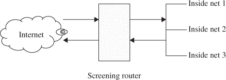
Packet filters typically set up a list of rules that are sequentially read line by line. Filtering rules can be applied based on source and destination IP addresses or network addresses, and TCP or UDP ports. Packet filters are read and then treated on a rule-by-rule basis. A packet filter will provide two actions, forward or discard. If the action is in the forward process, the action takes place to route the packet as normal if all conditions within the rule are met. The discard action will block all packets if the conditions in the rule are not met. Thus, a packet filter is a device that inspects each packet for predefined content. Although it does not provide an error-correcting ability, it is almost always the first line of defense. When packets are filtered at the external filter, it is usually called a screening router.
Since a packet filter can restrict all inbound traffic to a specific host, this restriction may prevent a hacker from being able to contact any other host within the internal network. However, the significant weakness with packet filters is that they cannot discriminate between good and bad packets. Even if a packet passes all the rules and is routed to the destination, packet filters cannot tell whether the routed packet contains good or malicious data. Another weakness of packet filters is their susceptibility to spoofing. In IP spoofing, an attacker sends packets with an incorrect source address. When this happen, replies will be sent to the apparent source address, not to the attacker. This might seem to be a problem.
Packet Filtering Rules
A packet filter applies a set of rules to each incoming IP packet and then forwards or discards the packet. The packet filter typically sets up a list of rules which may match fields in the IP or TCP header. If there is a match to one of the rules, that rule is able to determine whether to forward or discard the packet. If there is no match to any rule then two default actions (forward and discard) will be taken.
TELNET packet filtering
TELNET is a simple remote terminal access that allows a user to log onto a computer across an Internet. TELNET establishes a TCP connection and then passes keystrokes from the user's keyboard directly to the remote computer as if they had been typed on a keyboard attached to the remote machine. TELNET also carries output from the remote machine back to the user's screen. TELNET client software allows the user to specify a remote machine either by giving its domain name or IP address.
TELNET can be used to administer a UNIX machine. Windows NT does not provide a TELNET serve with the default installation, but a third-party service can be easily added. TELNET sends all user names and passwords in plaintext. Experienced hackers can hijack a TELNET session in progress. TELNET should only be used when the user can verify the entire network connecting the client and server, not over the Internet. All TELNET traffic should be filtered at the firewall. TELNET runs on TCP port 23.
For example, to disable the ability to TELNET into internal devices from the Internet, the information listed Table 11.1 tells the router to discard any packet going to or coming from TCP port 23. TELNET for remote access application runs on TCP port 23. It runs completely in open nonencryption, with no authentication other than the user name and password that are transmitted in clear. An asterisk (*) in a field indicates any value in that particular field. The packet-filtering rule sets are executed sequentially, from top to bottom.
Table 11.1 Telnet packet-filtering example
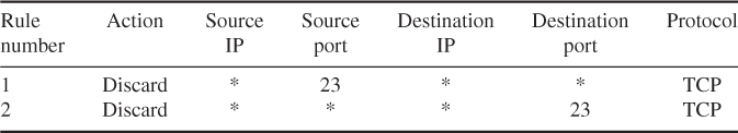
If a packet is passed through the filter and has a source port of 23, it will immediately be discarded. If a packet with a destination port of 23 is passed through this filter, it is discarded only after rule 2 has been applied. All other packets will be discarded.
FTP packet filtering
If the FTP service is to apply the same basic rule as applied to TELNET, the packet filter to allow or block FTP would look like Table 11.2. The FTP service is typically associated with using TCP ports 20 and 21.
Table 11.2 FTP packet-filtering example

One approach to handling FTP connections is explained with the following rule set. Rule 1 allows any host with the network address 192.168.10.0 to initiate a TCP session on any destination IP address on port 21. Rule 2 blocks any packet originating from any remote address with a source port of 20 and contacting a host with a network address 192.168.10.0 on any port less than 1024. Rule 3 allows any remote address that has a source port of 20 and is contacting any host with a network address of 192.168.10.0 on any port. Once a connection is set up, the ACK flag (![]() ) of a TCP segment is set to acknowledge segments sent from the other side. If any packet violates rule 2, it will be immediately discarded, and rule 3 will never be executed.
) of a TCP segment is set to acknowledge segments sent from the other side. If any packet violates rule 2, it will be immediately discarded, and rule 3 will never be executed.
With FTP, two TCP connections are used: a control connection to set up the file transfer and a data connection for the actual file transfer. The data connection uses a different port number to be assigned for the transfer. Remember that most servers live on low-numbered ports, but most outgoing calls tend to use higher-numbered ports, typically above 1024.
FTP is the first protocol for transferring or moving files across the Internet. Like many of the TCP/IP protocols, FTP was not designed with security in mind. It communicates with the server on two separate TCP ports 20 and 21. Each FTP server has a command channel, where the requests for data and directory listings are issued, and a data channel, over which the requested data is delivered.
FTP operates in two different modes (active and passive). In active mode, an FTP server receives commands on TCP/IP port 21 and exchanges data with the client. When a client contacts an FTP server in active mode and wants to send or receive data, the client picks an unused local TCP port between 1024 and 65 535, tells the server over the command channel, and listens for the server to connect on the chosen port. The server opens a connection from TCP port 20 to the specified port on the client machine. Once the connection is established, the data is passed across.
In passive mode, the command channel is still port 21 on the server, but the traditional data channel on port 20 is not used. Instead, when the client requests passive mode, the server picks an unused local TCP port between 1024 and 65 535 and tells the client. The client opens a connection to that port on the server. The server is listening on that port for the inbound connection from the client. Once the connection is established, the data flows across. Thus, since the client is initiating both the command and data channel connections to the server, most modern browsers use passive mode FTP for data accessing.
SMTP packet filtering
The sending and transmission of mail is the responsibility of a mail transport agent (MTA). The protocol behind nearly all MTAs is SMTP and its extension ESMTP. On the Internet, e-mail exchanges between mail servers are handled with SMTP. It is the protocol that transfers e-mail from one server to another, and it provides a basic e-mail facility for transferring messages among separate hosts. A host's SMTP server accepts mail and examines the destination IP address to decide whether to deliver the mail locally or to forward it to some other machine.
SMTP is a store/forward system, and such systems are well suited to firewall applications. SMTP receivers use TCP port 25; SMTP senders use a randomly selected port above 1023.
Most e-mail messages are addressed with hostnames instead of IP addresses, and the SMTP server uses DNS (Directory and Naming Services) to determine the matching IP address. If the same machines handle internal and external mail delivery, a hacker who can spoof DNS information may be able to cause mail that was intended for internal destinations to be delivered to an external host. A hacker who can manipulate DNS responses can redirect mail to a server under the control of the hacker. That server can then copy the mail and return it. This will introduce delays and will usually leave a trail in the log or message headers. Therefore, if it is desired to avoid situations where internal and external mail delivery are handled on the machine and internal names are resolved through DNS, it will be good practice to have the best configuration in which there is an external mail server and a separate internal mail server. The external mail server has the IP address of the internal mail server configured via a host file.
Sendmail (www.sendmail.org/) is the mailer commonly used on UNIX systems. Sendmail is very actively supported on security issues and has both an advantage and a disadvantage. Table 11.3 displays some examples of SMTP packet-filtering rule sets.
Table 11.3 SMTP packet-filtering examples

Packet filters offer their services at the network, transport, and session layers of the OSI model. Packet filters forward or deny packets based on information in each packet's header, such as the IP address or TCP port number. A packet-filtering firewall uses a rule set to determine which traffic should be forwarded and which should be blocked. Packet filters are then composed of rules that are read and treated on a rule-by-rule basis. Therefore, packet filtering is defined as the process of controlling access by examining packets based on the content of packet headers.
The following two subsections outline the specific details with relation to the circuit-level and application-level gateways for respective proxy services. Proxying provides Internet access for a single host or a small number of hosts. The proxy server evaluates requests from the client and decides which to pass on and which to disregard. If a request is approved, the proxy server talks to the real server on behalf of the client and proceeds to relay requests from the client to the real server and to relay the real server's answers back to the client. The concept of proxies is very important to firewall application because a proxy replaces the network IP address with another contingent address.
Proxies are classified into two basic forms:
- Circuit-level gateway.
- Application-level gateway.
Both circuit- and application-level gateways create a complete break between the internal premises network and external Internet. This break allows the firewall system to examine everything before passing it into or out of the internal network. Each of these gateways will be examined in turn in the following.
11.3.2 Circuit-Level Gateways
The circuit-level gateway represents a proxy server that statically defines what traffic will be forwarded. Circuit proxies always forward packets containing a given port number if that port number is permitted by the rule set. A circuit-leval gateway operates at the network level of the OSI model. This gateway acts as an IP address translator between the Internet and the internal system. The main advantage of a proxy server is its ability to provide network address translation (NAT). NAT hides the internal IP address from the Internet. NAT is the primary advantage of circuit-level gateways and provides security administrators with great flexibility when developing an address scheme internally. Circuit-level gateways are based on the same principles as packet filter firewalls. When the internal system sends out a series of packets, these packets appear at the circuit-level gateway where they are checked against the predetermined rules set. If the packets do not violate any rules, the gateway sends out the same packets on behalf of the internal system. The packets that appear on the Internet originate from the IP address of the gateway's external port, which is also the address that receives any replies. This process efficiently shields all internal information from the Internet. Figure 11.2 illustrates the circuit-level gateway for setting up two TCP connections.
Figure 11.2 Circuit-level gateway for setting up two TCP connections.

11.3.3 Application-Level Gateways
The application-level gateway represents a proxy server, performing at the TCP/IP application level, that is set up and torn down in response to a client request, rather than existing on a static basis. Application proxies forward packets only when a connection has been established using some known protocol. When the connection closes, a firewall using application proxies rejects individual packets, even if the packets contain port numbers allowed by a rule set.
The application gateway analyses the entire message instead of individual packets when sending or receiving data. When an inside host initiates a TCP/IP connection, the application gateway receives the request and checks it against a set of rules or filters. The application gateway (or proxy server) will then initiate a TCP/IP connection with the remote server. The server will generate TCP/IP responses based on the request from the proxy server. The responses will be sent to the proxy server (application gateway) where the responses are again checked against the proxy server's filters. If the remote server's response is permitted, the proxy server will then forward the response to the inside host.
Certain transport layer protocols work better than others. For example, TCP can easily be used through a proxy server because it is a connection-based protocol, while each User Datagram Protocol (UDP) packet should be treated as an individual message because UDP is connectionless. The proxy server must analyze each UDP packet and apply it to the filters separately, which slows down the proxy process. Internet Control Message Protocol (ICMP) programs are nearly impossible to proxy because ICMP messages do not work through an application-level gateway. For example, HTTP traffic is often used in conjunction with proxy servers, but an internal host could not ping a remote host through the proxy server. Application-level gateways (proxy servers) are used as intermediate devices when routing SMTP traffic to and from the internal network and the Internet.
The main advantage of a proxy server is its ability to provide NAT for shielding the internal network from the Internet. Figure 11.3 illustrates the application-level gateway acting as a relay of the application-level traffic.
Figure 11.3 Application-level gateway for acting as a relay of application-level traffic.

11.4 Firewall Designs
This section concerns how to implement a firewall strategy. The primary step in designing a secure firewall is obviously to prevent the firewall devices from being compromised by threats. To provide a certain level of security, the three basic firewall designs are considered: a single-homed bastion host, a dual-homed bastion host, and a screened subnet firewall. The first two options are for creating a screened host firewall, and the third option contains an additional packet-filtering router to achieve another level of security.
To achieve the most security with the least amount of effort is always desirable. When building firewall devices, the bastion host should keep the design simple with the fewest possible components, both hardware and software. A bastion host is a publicly accessible device. When Internet users attempt to access resources on the Internet network, the first device they encounter is a bastion host. Fewer running services on the bastion host will give a potential hacker less opportunity to overcome the firewall. Bastion hosts must check all incoming and outgoing traffic and enforce the rules specified in the security policy. Bastion hosts are armed with logging and alarm features to prevent attacks. When creating a bastion host, it must be kept in mind that its role will help to decide what is needed and how to configure the device.
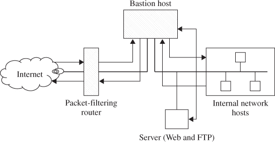
11.4.1 Screened Host Firewall (Single-Homed Bastion Host)
The first type of firewall is a screened host which uses asingle-homed bastion host plus a packet-filtering router, as shown in Figure 11.4. Single-homed bastion hosts can be configured as either circuit-level or application-level gateways. When using either of these two gateways, each of which is called a proxy server, the bastion host can hide the configuration of the internal network.
Figure 11.4 Screened host firewall system (single-homed bastion host).
NAT is essentially needed for developing an address scheme internally. It is a critical component of any firewall strategy. It translates the internal IP addresses to Internet Assigned Numbers Authority (IANA)-registered addresses to access the Internet. Hence, using NAT allows network administrators to use any internal IP address scheme.
The screened host firewall is designed such that all incoming and outgoing information is passed through the bastion host. The external screening router is configured to route all incoming traffic directly to the bastion host as indicated in Figure 11.4. The screening router is also configured to route outgoing traffic only if it originates from the bastion host. This kind of configuration prevents internal clients from bypassing the bastion host. Thus, the bastion host is configured to restrict unacceptable traffic and proxy acceptable traffic.
A single-homed implementation may allow a hacker to modify the router not to forward packets to the bastion host. This action would bypass the bastion host and allow the hacker directly into the network. But such a bypass usually does not happen because a network using a single-homed bastion host is normally configured to send packets only to the bastion host and not directly to the Internet.
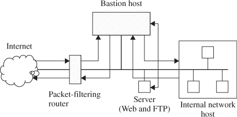
11.4.2 Screened Host Firewall (Dual-Homed Bastion Host)
The configuration of the screened host firewall using a dual-homed bastion host adds significant security, compared with a single-homed bastion host. As shown in Figure 11.5, a dual-homed bastion host has two network interfaces. This firewall implementation is secure due to the fact that it creates a complete break between the internal network and the external Internet. As with the single-homed bastion, all external traffic is forwarded directly to the bastion host for processing. However, a hacker may try to subvert the bastion host and the router to bypass the firewall mechanisms. Even if a hacker could defeat either the screening router or the dual-homed bastion host, the hacker would still have to penetrate the other. Nevertheless, a dual-homed bastion host removes even this possibility. It is also possible to implement NAT for dual-homed bastion hosts.
Figure 11.5 Screened host firewall system (dual-homed bastion host).
11.4.3 Screened Subnet Firewall
The third implementation of a firewall is the screened subnet, which is also known as a DMZ. This firewall is the most secure one among the three implementations, simply because it uses a bastion host to support both circuit- and application-level gateways. As shown in Figure 11.6, all publicly accessible devices, including modem and server, are placed inside the DMZ. This DMZ then functions as a small isolated network positioned between the Internet and the internal network. The screened subnet firewall contains external and internal screening routers. Each is configured such that its traffic flows only to or from the bastion host. This arrangement prevents any traffic from directly traversing the DMZ subnetwork. The external screening router uses standard filtering to restrict external access to the bastion host and rejects any traffic that does not come from the bastion host. This router also uses filters to prevent attacks such as IP spoofing and source routing. The internal screening router also uses rules to prevent spoofing and source routing. Like its external counterpart, this internal router rejects incoming packets that do not originate from the bastion host and sends only outgoing packets to the bastion host.
Figure 11.6 Screened subnet firewall system.
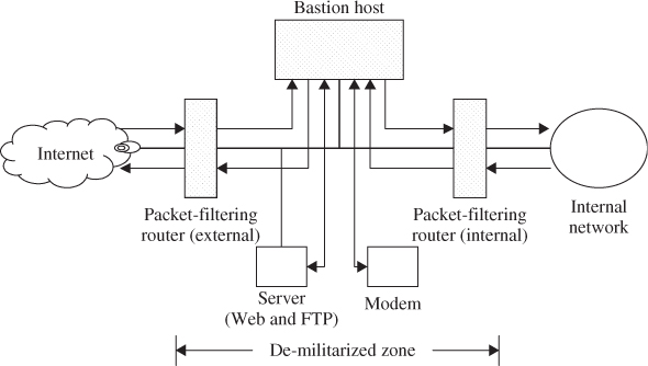
The benefits of the screened subnet firewall are based on the following facts. First, a hacker must subvert three separate tri-homed interfaces when he or she wants to access the internal network. But it is almost infeasible. Second, the internal network is effectively invisible to the Internet because all inbound/outbound packets go directly through the DMZ. This arrangement makes it impossible for a hacker to gain information about the internal systems because only the DMZ is advertized in the routing tables and other Internet information. Third, internal users cannot access the Internet without going through the bastion host because the routing information is contained within the network.
11.5 IDS Against Cyber Attacks
Recently, the information technology (IT) industry has witnessed the development of many cyber security solutions for protecting IT networks and reducing their vulnerability to cyber attacks. From firewalls to intrusion detection systems (IDSs), their security solutions have been progressed effectively in some extent for preserving data integrity, protecting data confidentiality, and maintaining data availability. This section will present a survey and comparison of Internet worm/virus detection against cyber defense.
11.5.1 Internet Worm Detection
In order to reduce the damage effectively caused by the fast propagation of malicious Internet worms, exiting IDSs should be strong enough to combat against the propagation worms, as well as to provide the security-related regulations of their monitoring networks.
A computer worm is a standalone malware program which replicates itself and spreads to other devices via network by utilizing vulnerabilities on the target devices. Therefore, a worm is a malicious piece of codes that self-progresses via network connections, exploiting security flaws in computers on the network.
Passive worms will require certain host behavior or human intervention to propagate itself until it is contacted by another host. Since the Morris worm was found in 1988, Internet worms have caused the most extensive and widespread damage of all kinds of computer attacks. Thus, an Internet worm is defined as a piece of malicious code that duplicates and propagates itself.
The life of a worm, after it is released, typically includes the following four phases:
- Target finding. Target finding is the first step in a worm's life to discover vulnerable hosts.
- Worm transferring. Transferring is referred to send a copy of the worm to the target after the victim (target) is discovered.
- Worm activation. Worm code starts to activate, duplicate, and propagate by itself until the target is discovered.
- Worm infection. Infection is the result of the worm, performing its malicious activities on the target host.
Differently from Computer Virus, the worm is a standalone program which can replicate itself through the network to spread, so it does not need to be attached. It makes the network performance weak by consuming bandwidth, increasing network traffic, or causing the denial of service (DoS). Morris worm, Blaster worm, Sasser worm, and Mydoom worm were some example of most notorious worms.
Morris worm (2 November, 1988) was written by a Cornell University student, Robert Tappan Morris, and reported to infect about 6000 major UNIX machines (damaging size is about $100 000–dollar;10 000 000). Blaster worm (11 August, 2003) spread by exploiting BOF (buffer overflow) attack in DCOM RPC service of Windows operating system (OS), displayed some message, and rebooted the victim. Sasser worm might be the evolution of the Blast worm. Mydoom worm (26 January, 2004) was transmitted to attack Windows OS via e-mail with attachment, using user's address book. It evolved to many versions. It also affected South Korea and the United States on July 2009. Nowadays, the worm will install Trojan horse or backdoor into the PC and make the victim PC as botnet zombie.
11.5.2 Computer Virus
The Computer Virus is a kind of malicious program which can damage the victim computer and spread itself to another computer. The word “Virus” is used for most of the malicious program and it is confused with other programs, but the Virus, worm botnet, or other terms is distinct from one another.
The Virus destroys or disturbs the computer systems and user files, replicating itself via some media including hard disk, removable disc (floppy disk, USB, etc.), or network. Almost all Viruses must be attached to an executive file to be executed, because it cannot run without any action of human. Before the network is widespread, most Viruses spread via floppy disks. PC was booted from floppy disks and most of user files are also transferred by them. So the Virus in that time infected the floppy or hard disk files, or the boot sector of them. When the PC is booted or a user runs the virus attached files, the Virus uploads the malicious module and replication module to memory, sometimes it scans the victim host or files and attaches itself to them. The Virus used binary executable files, boot record, come script files, documents containing macro, and so on to transmit and infect.
11.5.3 Special Kind of Viruses
Trojan Horse
Trojan horse (or Trojan) is made to steal some information by social engineering. The term Trojan horse is derived from Greek mythology. The Trojan gives a cracker remote access permission like the Greek soldiers, avoiding detection of their user. It looks like some useful or helpful program, or looks like legitimate access process, but it just steal password, card number, or other useful information. The popular Trojan are Netbus, Back Orifice, Zeus, and so on.
Botnet
Botnet is the set of zombie computers connected to the Internet. Each compromised zombie computer is called as bot, and the botmaster, called as C&C (Command & Control server), controls these bots. Some Web site or e-mail has the malicious code, and if a user downloads and runs the program by curiosity or mistake, the PC is compromised by the program but the user cannot notice it. The bot has Trojan horse, backdoor, or other command tunnel, so the C&C can do anything with these bots.
Most of the bots run hidden and communicate via covert channel, so the user can hardly notice the bot. And botnet servers often liaise with each servers, the real size of bot network may be more larger than we can count.
The purpose of botnet is various, such as denial of service, STMP mail relays for sending spam mail, click fraud, steal some financial information, and login information.
There are so many kinds of botnet, and Stuxnet (June, 2010) is the most popular botnet of them. It was written to attack the industrial system with closed network, infected by USB memory. When it penetrates into one network, it spreads itself in the network and controls all of the systems. It used the system vulnerabilities such as LNK, Print Spooler, and Server Service.
Key Logger
Key logger program monitors the action of the key inputs. The key logger is of two types, software and hardware. This section concerns the software type only. It is also installed in the victim computers and logs all the strokes of keys. They save the log into some files or send the logs to the hacker by network. Key logger can steal the action of key input by kernel level, memory level, API level, packet level, and so on.
11.6 Intrusion Detections Systems
The lack of knowledge about security makes the people vulnerable to the damage due to acts of violence such as physical or electronical acts, putting on the risk the integrity of persons, companies for the loss or damage of electronic documents, physical areas, IT infrastructures, and so on.
From the point of view of the IT environment, we have to consider the implementation of IDSs to provide reliable information to network-administrator-related security of physical (Servers, Databases, Firewall, LAN, PCs, etc.) and electronic files which are considering the most valuable assets in companies.
This section presents several IDS systems which are typically deployed in IT networks.
11.6.1 Network-Based Intrusion Detection System (NIDS)
A network-based intrusion detection system (NIDS) monitors network traffic for particular network segments or devices and analyzes network, transport, and application protocols to identify suspicious activity.
NIDSs typically perform most of their analysis at the application layer such as HTTP, DNS, FTP, SMTP, and SNMP. They also analyze activity at the transport and network layers both to identify attacks at those layers and to facilitate the analysis of the application layer activity (e.g., a TCP port number may indicate which application is being used). Some NIDSs also perform limited analysis at the hardware layer.
A typical NIDS is composed of sensors, one or more management servers, multiple consoles, and optionally, one or more database servers (if the NIDS supports their use). All of these components are similar to other types of IDS technologies, except for the sensors. An NIDS sensor monitors and analyzes network activity on one or more network segments. The network interface cards that will be performing monitoring are placed into promiscuous mode, which means that they will accept all incoming packets that they see, regardless of their intended destinations. Most IDS deployments use multiple sensors, with large deployments having hundreds of sensors.
Sensors are available in two formats:
- Appliance. An appliance-based sensor consists of specialized hardware and sensor software. The hardware is typically optimized for sensor use, including specialized NICs and NIC drivers for efficient capture of packets, and specialized processors or other hardware components that assist in analysis. Parts or all of the IDS software might reside in firmware for increased efficiency. Appliances often use a customized, hardened OS that administrators are not intended to access directly.
- Software Only. Some vendors sell sensor software without an appliance. Administrators can install the software onto hosts that meet certainspecifications. The sensor software might include a customized OS or it might be installed onto a standard OS just as any other application would.
Organizations should consider using management networks for their NIDS deployments whenever feasible. If an IDS is deployed without a separate management network, organizations should consider whether or not a VLAN is needed to protect the IDS communications.
In addition to choosing the appropriate network for the components, administrators also need to decide where the IDS sensors should be located. Sensors can be deployed in one of two modes:
- Inline. An inline sensor is deployed so that the network traffic it is monitoring must pass through it, much like the traffic flow associated with a firewall. In fact, some inline sensors are hybrid firewall/IDS devices, while others are simply IDSs. The primary motivation for deploying IDS sensors inline is to enable them to stop attacks by blocking network traffic. Inline sensors are typically placed where network firewalls and other network security devices would be placed—at the divisions between networks, such as connections with external networks and borders between different internal networks that should be segregated. Inline sensors that are not hybrid firewall/IDS devices are often deployed on the more secure side of a network division so that they have less traffic to process. Sensors can also be placed on the less secure side of a network division to provide protection for and reduce the load on the dividing device, such as a firewall.
- Passive. A passive sensor is deployed so that it monitors a copy of the actual network traffic; no traffic actually passes through the sensor. Passive sensors are typically deployed so that they can monitor key network locations, such as the divisions between networks, and key network segments, such as activity on a DMZ subnet. Passive sensors can monitor traffic through various methods, including the following:
- Spanning Port. Many switches have a spanning port, which is a port that can see all network traffic going through the switch. Connecting a sensor to a spanning port can allow it to monitor traffic going to and from many hosts. Although this monitoring method is relatively easy and inexpensive, it can also be problematic. If a switch is configured or reconfigured incorrectly, the spanning port might not be able to see all the traffic. Another problem with spanning ports is that their use can be resource-intensive; when a switch is under heavy loads, its spanning port might not be able to see all traffic or spanning might be temporarily disabled. Also, many switches have only one spanning port, and there is often a need to have multiple technologies, such as network monitoring tools, network forensic analysis tools, and other IDS sensors, to monitor the same traffic.
- Network Tap. A network tap is a direct connection between a sensor and the physical network media itself, such as a fiber-optic cable. The tap provides the sensor with a copy of all network traffic being carried by the media. Installing a tap generally involves some network downtime, and problems with a tap could cause additional downtime. Also, unlike spanning ports, which are usually already present throughout an organization, network taps need to be purchased as add-ons to the network.
- IDS Load Balancer. An IDS load balancer is a device that aggregates and directs network traffic to monitoring systems, including IDS sensors. A load balancer can receive copies of network traffic from one or more spanning ports or network taps and aggregate traffic from different networks (e.g., reassemble a session that was split between two networks). The load balancer then distributes copies of the traffic to one or more listening devices, including IDS sensors, based on a set of rules configured by an administrator. The rules tell the load balancer which types of traffic to provide to each listening device.
NIDS products provide a wide variety of security capabilities. Some NIDSs offer limited information gathering capabilities, which means that they can collect information on hosts and the network activity involving those hosts. NIDSs typically perform extensive logging of data related to detected events. This data can be used to confirm the validity of alerts, investigate incidents, and correlate events between the IDS and other logging sources. NIDSs typically offer extensive and broad detection capabilities. Most products use a combination of signature-based detection, anomaly-based detection, and stateful protocol analysis techniques to perform in-depth analysis of common protocols; organizations should use NIDS products that use such a combination of techniques. The detection methods are usually tightly interwoven; for example, a stateful protocol analysis engine might parse activity into requests and responses, each of which is examined for anomalies and compared to signatures of known bad activity. Some products also use the same techniques and provide the same functionality as network behavior analysis (NBA) software.
NIDS sensors offer various prevention capabilities, including Passive only, Inline only, and both Passive and Inline.
11.6.2 Wireless Intrusion Detection System (WIDS)
A wireless intrusion detection system (WIDS) monitors wireless network traffic and analyzes its wireless networking protocols to identify suspicious activity. The typical components in a WIDS are the same as an NIDS: consoles,database servers (optional), management servers, and sensors. However, unlike an NIDS sensor, which can see all packets on the networks it monitors, a WIDS sensor works by sampling traffic because it can only monitor a single channel at a time. The longer a single channel is monitored, the more likely it is that the sensor will miss malicious activity occurring on other channels. To avoid this, sensors typically change channels frequently, so that they can monitor each channel a few times per second.
Wireless sensors are available in multiple forms. A dedicated sensor is a fixed or mobile device that performs WIDS functions but does not pass network traffic from source to destination. The other wireless sensor forms are bundled with access points (AP) or wireless switches. Because dedicated sensors can focus on detection and do not need to carry wireless traffic, they typically offer stronger detection capabilities than wireless sensors bundled with AP or wireless switches. However, dedicated sensors are often more expensive to acquire, install, and maintain than bundled sensors because bundled sensors can be installed on existing hardware, whereas dedicated sensors involve additional hardware and software. Organizations should consider both security and cost when selecting WIDS sensors.
WIDS components are typically connected to each other through a wired network. Because there should already be a strictly controlled separation between the wireless and wired networks, using either a management network or a standard network should be acceptable for WIDS components. Choosing sensor locations for a WIDS deployment is a fundamentally different problem than choosing locations for any other type of IDS sensor. If the organization uses termdefwireless local area networks (WLAN), wireless sensors should be deployed so that they monitor the range of the WLANs. Many organizations also want to deploy sensors to monitor parts of their facilities where there should be no WLAN activity, as well as channels and bands that the organization's WLANs should not use. Other considerations for selecting sensor locations include physical security, sensor range, wired network connection availability, cost, and AP and wireless switch locations.
WIDSs provide several types of security capabilities. Most can collect information on observed wireless devices and WLANs and perform extensive logging of event data. WIDSs can detect attacks, misconfigurations, and policy violations at the WLAN protocol level. Organizations should use WIDS products that use a combination of detection techniques to achieve broader and more accurate detection. Examples of events detected by WIDSs are unauthorized WLANs and WLAN devices, poorly secured WLAN devices, unusual usage patterns, the use of active wireless network scanners, denial of service attacks, and impersonation and man-in-the-middle attacks. Most WIDS sensors can also identify the physical location of a detected threat by using triangulation.
Compared to other forms of IDS, WIDS is generally more accurate; this is largely due to its limited scope (analyzing wireless networking protocols). WIDSs usually require some tuning and customization to improve their detectionaccuracy. The main effort is in specifying which WLANs, APs, and STAs are authorized and in entering the policy characteristics into the WIDS software. Besides reviewing tuning and customizations periodically to ensure that they are still accurate, administrators should also ensure that changes to building plans are incorporated occasionally. This is needed for accurate identification of the physical location of threats and accurate planning of sensor deployments.
Although WIDSs offer robust detection capabilities, they do have some significant limitations. WIDSs cannot detect certain types of attacks against wireless networks, such as attacks involving passive monitoring and off-line processing of wireless traffic. WIDSs are also susceptible to evasion techniques, especially those involving knowledge of a product's channel scanning scheme. Channel scanning can also impact network forensics because each sensor sees only a fraction of the activity on each channel. WIDS sensors are also susceptible to denial of service attacks and physical attacks.
WIDS sensors can offer intrusion prevention capabilities. Some sensors can instruct end points to terminate a session and prevent a new session from being established. Some sensors can instruct a switch on the wired network to block network activity for a particular wireless end point; however, this method can only block wired network communications and will not stop an end point from continuing to perform malicious actions through wireless protocols. Most IDS sensors allow administrators to specify the prevention capability configuration for each type of alert. Prevention actions can affect sensor monitoring; for example, if a sensor is transmitting signals to terminate connections, it may not be able to perform channel scanning to monitor other communications until it has completed the prevention action. To mitigate this, some sensors have two radios—one for monitoring and detection and the other for performing prevention actions. When selecting sensors, organizations should consider what prevention actions may need to be performed and how the sensor's detection capabilities could be affected by performing prevention actions.
11.6.3 Network Behavior Analysis System (NBAS)
A network behavior analysis system (NBAS) examines network traffic or statistics on network traffic to identify unusual traffic flows. NBA solutions usually have sensors and consoles, with some products also offering management servers. Some sensors are similar to NIDS sensors in that they sniff packets to monitor network activity on one or a few network segments. Other NBA sensors do not monitor the networks directly, but instead rely on network flow information provided by routers and other networking devices.
Most NBA sensors can be deployed in passive mode only, using the same connection methods (e.g., network tap, switch spanning port) as NIDSs. Passive sensors that are performing direct network monitoring should be placed so that they can monitor key network locations, such as the divisions between networks, and key network segments, such as DMZ subnets. Inline sensors are typically intended for network perimeter use, so they would be deployed in close proximity to the perimeter firewalls, often in front to limit incoming attacks that could overwhelm the firewalls.
NBA products provide a variety of security capabilities. They offer extensive information gathering capabilities, collecting detailed information on each observed host and constantly monitoring network activity for changes to this information. NBA technologies typically perform extensive logging of data related to detected events. They also typically have the capability to detect several types of malicious activity, including DoS attacks, scanning, worms, unexpected application services, and policy violations, such as a client system providing network services to other systems. Because NBA sensors work primarily by detecting significant deviations from normal behavior, they are most accurate at detecting attacks that generate large amounts of network activity in a short period of time and attacks that have unusual flow patterns. Most NBA sensors can also reconstruct a series of observed events to determine the origin of a threat.
NBA products automatically update their baselines on an ongoing basis. As a result, typically, there is not much tuning or customization to be done, other than updating firewall rule-set-like policies that most products support. A few NBA products offer limited signature customization capabilities; these are most helpful for inline sensors because they can use the signatures to find and block attacks that a firewall or router might not be capable of blocking. Besides reviewing tuning and customizations periodically to ensure that they are still accurate, administrators should also ensure that significant changes to hosts are incorporated, such as new hosts and new services. Generally, it is not feasible to automatically link NBA systems with change management systems, but administrators could review change management records regularly and adjust host inventory information in the NBA to prevent false positives.
NBA technologies have some significant limitations. They are delayed in detecting attacks because of their data sources, especially when they rely on flow data from routers and other network devices. This data is often transferred to the NBA in batches from every minute to a few times an hour. Attacks that occur quickly may not be detected until they have already disrupted or damaged systems. This delay can be avoided by using sensors that do their own packet captures and analysis; however, this is much more resource-intensive than analyzing flow data. Also, a single sensor can analyze flow data from many networks, while a single sensor can generally directly monitor only a few networks at once. Therefore, to do direct monitoring instead of using flow data, organizations might have to purchase more powerful sensors and/or more sensors.
11.6.4 Host-Based Intrusion Detection System (HIDS)
Host-based intrusion detection systems (HIDSs) monitor the characteristics of a single host and the events occurring within that host for suspicious activity. Examples of the types of characteristics an HIDS might monitor are wired and wireless network traffic, system logs, running processes, file access and modification, and system and application configuration changes. Most HIDSs have detection software known as agents installed on the hosts of interest. Each agent monitors activity on a single host and if prevention capabilities are enabled, also performs prevention actions. The agents transmit data to management servers. Each agent is typically designed to protect a server, a desktop or laptop, or an application service.
The network architecture for HIDS deployments is typically very simple. Because the agents are deployed to existing hosts on the organization's networks, the components usually communicate over those networks instead of using a management network. HIDS agents are most commonly deployed to critical hosts such as publicly accessible servers and servers containing sensitive information. However, because agents are available for various server and desktop/laptop OSs, as well as specific server applications, organizations could potentially deploy agents to most of their servers and desktops/laptops. Organizations should consider several criteria when selecting agent locations, including the need to analyze activity that cannot be monitored by other security controls; the cost of the agents' deployment, maintenance, and monitoring; the OSs and applications supported by the agents; the importance of each host's data or services; and the ability of the network infrastructure to support the agents' communications.
Most IDS agents alter the internal architecture of the hosts on which they are installed through shims, which are layers of code placed between existing layers of code. Although it is less intrusive to the host to perform monitoring without shims, which reduces the possibility of the IDS interfering with the host's normal operations, monitoring without shims is also generally less accurate at detecting threats and often precludes the performance of effective prevention actions.
HIDSs provide a variety of security capabilities. They typically perform extensive logging of data related to detected events and can detect several types of malicious activity. Detection techniques used include code analysis, network traffic analysis, network traffic filtering, filesystem monitoring, log analysis, and network configuration monitoring. HIDSs that use combinations of several detection techniques should generally be capable of achieving more accurate detection than products that use one or a few techniques, because each technique can monitor different characteristics of hosts. Organizations should determine which characteristics need to be monitored and select IDS products that provide adequate monitoring and analysis of those characteristics.
HIDSs usually require considerable tuning and customization; for example, many rely on observing host activity and developing baselines or profiles of expected behavior. Others need to be configured with detailed policies that define exactly how each application on a host should behave. As the host environment changes, administrators should ensure that HIDS policies are updated to take those changes into account.
HIDSs have some significant limitations. Some detection techniques are performed only periodically, such as hourly or a few times a day, to identify events that have already happened, causing significant delay in identifying certain events. Also, many HIDSs forward their alert data to the management servers in batches a few times an hour, which can cause delays in initiating response actions. Because HIDSs run agents on the hosts being monitored, they can impact host performance because of the resources the agents consume. Installing an agent can also cause conflicts with existing host security controls, such as personal firewalls and VPN clients. Agent upgrades and some configuration changes can also necessitate rebooting the monitored hosts.
HIDSs offer various intrusion prevention capabilities; these vary based on the detection techniques used by each product. Code analysis techniques can prevent code from being executed; this can be very effective at stopping both known and previously unknown attacks. Network traffic analysis can stop incoming and outgoing network traffic containing network, transport, or application layer attacks; wireless networking protocol attacks; and the use of unauthorized applications and protocols. Network traffic filtering works as a host-based firewall and stops unauthorized access and acceptable use policy violations. Filesystem monitoring can prevent files from being accessed, modified, replaced, or deleted, which can stop malware installation and other attacks involving inappropriate file access. Other HIDS detection techniques generally do not support prevention actions because they identify events well after they have occurred.
Some HIDSs offer additional capabilities related to intrusion detection and prevention, such as enforcing restrictions on the use of removable media, detecting the activation or use of audiovisual devices, automatically hardening hosts on an ongoing basis, monitoring the status of running processes and restarting failed ones, and performing network traffic sanitization.
11.6.5 Signature-Based Systems
A signature-based IDS is based on pattern matching techniques. The IDS contains a database of patterns. Some patterns are well known by public program or domain, for example, Snort (http://www.snort.org/) and some are found by signature-based IDS companies. Using database of already found signature is much like antivirus software.
The IDS tries to match these signatures with the analyzed data. If a match is found, an alert is raised.
This approach usually yields good results in terms of few false positives. For few false positives, the Users try to select needed signatures, a task known as tuning, to avoid future false alerts. Tuning is performed once, and then updated from time totime. Thanks to tuning, a signature-based IDS generally generates a low rate of false alerts.
Even though the IDS make good results, it has drawbacks. First, all new attacks or polymorphic attacks, for example, zero-day attack, will go unnoticed until the responsible signatures are updated to database. It is because the IDS only tries to match signatures of its database with the attacks.
The IDS is not likely to detect even slight modifications of a known attack. Thus, attackers have a window of opportunity to gain control of the system or application under attack.
Second, the IDS need to be updated regularly, increasing the IT personnel workload and required skills.
Developing a new signature is tedious and hard work. Once an attack is made public, first, the experts need to analyze it carefully. The attack could exploit either a well-known vulnerability or a new one. The experts should develop the signature to detect the way the attack exploits a given vulnerability rather than the attack only. For example, BOF attacks could exploit different attack vectors, but those vectors will show common length. This is because attackers try to modify the attack payload without altering the attack effectiveness. So there are more chances to detect attack variations with just one signature.
A signature-based IDS raises classified alerts, for example, BOF or SQL Injection, and this classification is assigned “off-line” during the development of the signature. The importance of classification is threefold. First, Security teams can prioritize alerts without having to inspect them. Second, Security teams deploy automatic defensive countermeasures to react to certain disruptive attacks as soon as they take place, for example, dropping network traffic when a BOF is detected or changing some rules in firewall systems. Third, alerts can be correlated with each other and with other system logs, for example, firewall logs, to detect multistep attacks, that is, attacks that require the attacker to execute several actions to achieve his/her goal, and to reduce false alerts by identifying root causes. Thus, determining the attack class helps these tasks.
11.6.6 Anomaly-Based Systems
The deployment of an anomaly-based IDS typically requires expert personnel. Several parameters need to be configured, such as the duration of the training phase or the similarity metric. Every environment being different, guidelines are hard to give. Each anomaly-based IDS is also different from the others (while all signature-based IDSs work in a similar manner). Users gain little knowledge from subsequent installations; hence, deployment tasks are likely to be trial-and-error processes. Users mainly criticize three aspects of the management of current anomaly-based IDSs, each of which increases the user effort needed to run the IDS,namely,
False Alerts
Because of its statistical nature, an anomaly-based IDS is bound to raise a higher number of false alerts than a signature-based IDS. As a matter of fact, the classification of a certain input for a signature-based IDS is predetermined (for malicious inputs), while the classification of inputs for an anomaly-based IDS depends on the training data. Thus, different anomaly-based model instances could classify the same input differently.
False alerting is a well-known problem of IDSs in general and anomaly-based IDSs in particular. Security teams need to verify each raised alert; thus, an ineffective system (i.e., a system prone to raise a high number of false alerts) will require more personnel for its management.
Black Box Approach
An anomaly-based IDS carries out detection as a black box. Users have little control: quite often, they can adjust only the similarity metric used to discern licit traffic from malicious activities. Because most anomaly-based IDSs employ complex mathematical models (think of neural networks), users can neither precisely understand how the IDS engine discerns normal input nor refine the IDS model to avoid certain false alerts or to improve attack detection. Users need to spend a good deal of time to understand the inner working of the system, and they must be experts.
Lack of Attack Classification
An anomaly-based IDS raises an alert every time its model differs from the current input. The cause of the anomaly itself is unknown to the IDS. It holds little information to determine the attack class (other than the targeted IP address/TCP port and the IP source of attack). Because the model employed by the detection engine is locally built during a certain timeframe, each model is likely to be different. Hence, it is difficult to develop an off-line classifier suitable for any anomaly-based IDS instance. Because an anomaly-based IDS is supposed to detect unknown attacks, or slight modifications of well-known attacks, manual classification or the application of some heuristics are currently the only possible choices. However, manual classification is not feasible and the heuristics deliver results in a restricted context only (because the “traits” of each attack must be known before). Because alerts come unclassified, no automatic countermeasure can be activated to react to a certain threat.
Because of all the difficulties listed above for an anomaly-based IDS, a signature-based IDS is the obvious choice when users have to monitor complex systems, such as modern corporate networks, despite its inability to deal with zero-day attacks. Users can accomplish tuning more easily to avoid false alerts (thereby saving overall time), they can write their own set of signatures to detect attacks and a signature-based IDS automatically performs alert classification. An anomaly-based IDS lacks these features because researchers have mainly focused on enhancing attack detection and have not considered usability.
As a matter of fact, users could improve the usability of current anomaly-based IDSs by setting the similarity metric in such a way that the IDS generate fewer alerts. However, the detection rate would be (negatively) affected as well, thereby reducing the only advantage an anomaly-based IDS has over a signature-based IDS.
11.6.7 Evasion Techniques of IDS Systems
Attackers continuously try to find new exploits to intrude a system, while IDS system developers attempt to analyze and detect attacks. Here, four common evasions are introduced.
Denial of Service
DoS attack intends to overwhelm network bandwidth or use system resources like CPU usage and the memory space of the system up. To do this, DoS attacks generate huge volume of network traffic and exploit the vulnerability of detection algorithm like slowing down the signature matching algorithm with modified network payload. In case of Snort, it uses backtracking for covering all possible pattern matching. The attacker could exploit this and modify the payload to take worst execution time for rule matching.
Packet Splitting
Packet splitting chops IP datagrams or TCP streams into nonoverlapping fragments known as IP fragmentations and TCP segmentation. Because of limited system resource, some IDS systems just try to match patterns to each fragmented packet without reassembling those. In this case, IDS could not detect attacking pattern in the reassembled packet. For example, an IDS may look for /bin/sh or/bin/bash to check whether the command execution code is included or not in the payload. But the attacker can deliberately split the payload with the signature into two segments, one containing /bin and the other containing /sh. If the IPS does not reassemble the two segments, it will be unable to find the signature in either segment, so the attacker can evade its detection.
Duplicate Insertion
Attackers could send duplicate or overlapping segments to IDS to confuse or neglect the content from IDS.
Because IDS system does not know network topology and victim system's OS information, if attackers send packets modifying TTL values with same sequence number, when IDS systems reassemble the packets, it gets confused with that. If IDS considered all possible combinations of packet reassembly, it gets confused as to which combination is the correct one. However, the victim system could not get all the packets sent by the attacker but the attacking packets only.
For example, an attacker sends fragmented and duplicated packets like:
In this case, IDS receives all five packets and is confused how to reassemble them and hence cannot detect them as attacker packets. If hop number from attacker to victim is 20, second and fourth packets are dropped and only first, third, and fifth packets are delivered to victim system. The reassembled content is/bin/bash.
Payload Mutation
An attacker transforms malicious packet's payloads into semantically equivalent ones. Transformed packets will be different for IDS systems. Especially, the uniform resource identifier (URI) of an HTTP request could be the target of the attack. URI characters can be encoded to hexadecimal values like
Original URI: http://www.google.com?a=b
Transformed URI: http%3a%2f%2fwww.google.com%3fa=b
Attackers could transform several mutated expressions using the libwhisker library (www.wiretrip.net/rfp/ txt/whiskerids.html). This includes not only character transformation but also self-reference directory. For example, /abc/def/../def/gf/../../../bin/abc/../sh means /bin/sh.
Before trying to match patterns to URI, IDS systems need to process URL normalization (http://en.wikipedia.org/ wiki/URL_normalization) for transformed URI to original URI. IDS systems without this process will fail to detect the packet as attack.