
Chapter 5
Hash Function, Message Digest, and Message Authentication Code
As digital signature technology becomes more widely understood and utilized, many countries worldwide are competitively developing their own signature standards for their use and applications.
Some electronic applications utilizing digital signatures in electronic commerce (e-commerce) include e-mail and financial transactions. E-mail may need to be digitally signed, where sensitive information is being transmitted and security services such as sender authentication, message integrity, and nonrepudiation are desired. Financial transactions, in which money is being transferred directly or in exchange for services and goods, could also benefit from the use of digital signatures. Signing the message digest rather than the message often improves the efficiency of the process because the message digest is usually much smaller than the message.
In e-commerce, it is often necessary for communication parties to verify each other's identity. One practical way to do this is with the use of cryptographic authentication protocols employing a one-way hash function. Division into fixed-bit blocks can be accomplished by mapping the variable-length message onto the suitable-bit value by padding with all zeros, including 1-bit flag and the original message length in hex. Appropriate padding is needed to force the message to divide conveniently into certain fixed lengths. Several algorithms are introduced in order to compute message digests by employing several hash functions. The hash functions dealt with in this chapter are DMDC (DES-like Message Digest Computation) (1994), MD5 (1992), and SHA-1 (1995).
5.1 DMDC Algorithm
DMDC uses a DES (Data Encryption Standard) variant as a one-way hash function. In 1994, this scheme was introduced to compute the 18-bit authentication data with CDMA cellular mobile communications system. DMDC divides messages into blocks of 64 bits. The DMDC hash function generates message digests with variable sizes—18, 32, 64, or 128 bits. This scheme is appropriate for the use of digital signatures and hence it can be employed to increaseInternet security.
The message to be signed is first divided into a sequence of 64-bit blocks:
![]()
Appropriate padding rules need to be devised for messages that do not divide conveniently. The adjacent message blocks are hashed together with a self-generated key. A better approach is to use one block (64 bits) of the correct message length as the key.
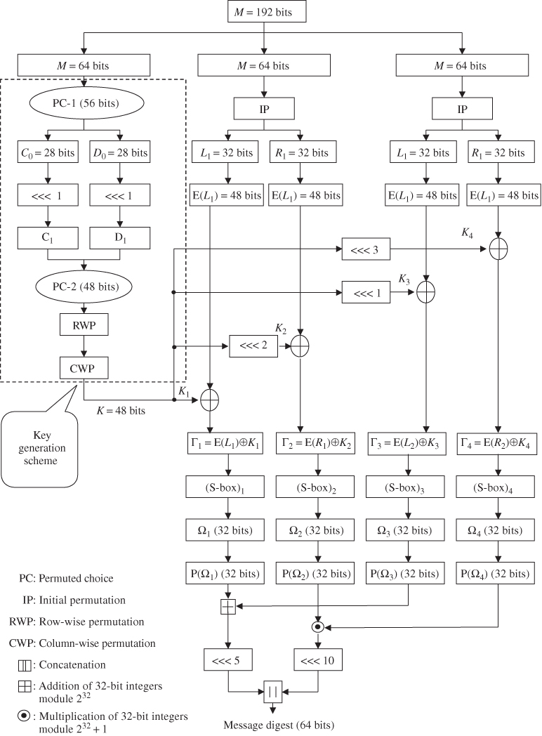
Figure 5.1 shows a typical scheme for hash code computation for ![]() bits using DMDC.
bits using DMDC.
Figure 5.1 DMDC algorithm for ![]() bits.
bits.
5.1.1 Key Schedule
One authentication problem in the CDMA mobile system is how to confirm the identity of the mobile station by exchanging information between a mobile station and base station. When the authentication field of the access parameters message is set to “01”, the mobile station attempts to register by sending a registration request message on the access channel and the authentication procedure will be performed. Computing the authentication data of mobile station registrations, it is necessary to have a 152-bit message value which complies with RAND (32 bits), ESN (32 bits), MIN (24 bits), and SSD-A (64 bits):
The 192-bit value is composed of 152-bit message length and 40-bit padding. Suppose ![]() ,
, ![]() , and
, and ![]() are decompositions of a 192-bit padded message.
are decompositions of a 192-bit padded message. ![]() bits will be used as input to the key generation scheme in Figure 5.1. The Permuted Choice 2 operation will produce the 48-bit key that is arranged into a
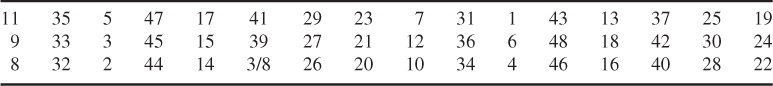
bits will be used as input to the key generation scheme in Figure 5.1. The Permuted Choice 2 operation will produce the 48-bit key that is arranged into a ![]() array as shown below:
array as shown below:
Input (column by column)

Row-wise permutation

Column-wise permutation

→ Output (row by row)
Thus, a 48-bit key generation from ![]() is computed as shown in Table 5.1.
is computed as shown in Table 5.1.
Table 5.1 A 48-bit key generation by row/column permutations

Note that no 1-bit flag and no message length in hex are inserted in this example. The 48-bit key generation using row/column permutations is given below. Assume that the first data block ![]() is used as the key input. Using Table 3.1 (PC-1),
is used as the key input. Using Table 3.1 (PC-1), ![]() can be split into two blocks:
can be split into two blocks:
![]()
As shown in Table 3.2, ![]() and
and ![]() are obtained from
are obtained from ![]() and
and ![]() by shifting 1 bit to the left, respectively.
by shifting 1 bit to the left, respectively.
![]()
Using Table 3.3 (PC-2), the 48-bit compressed key is computed as:
![]()
Finally, using Table 5.1, the 48-bit key with the row/column permutations is computed as:
![]()
This is the key block to be provided for ![]() and
and ![]() , as shown in Example 5.2.
, as shown in Example 5.2.
Expansion of these four data blocks using Table 3.5 yields

The 48-bit key, ![]() , obtained through row/column permutations, should be shifted 0, 2, 1, and 3 bits to the left such that
, obtained through row/column permutations, should be shifted 0, 2, 1, and 3 bits to the left such that

These four keys are used for XORing (eXclusive ORing) with expanded blocks such that
These four ![]() 's, are inputs to the (S-box)
's, are inputs to the (S-box)![]() , respectively.
, respectively.
Applying the operation of Table 3.7 to each ![]() yields:
yields:
These four data blocks resulting from Table 3.7 are used for the computation of message digests (or hash codes), as shown in Example 5.3.
5.1.2 Computation of Message Digests
Since we have already calculated ![]() in Example 5.2, the message digest of 32 bits is ready to be computed from Figure 5.2:
in Example 5.2, the message digest of 32 bits is ready to be computed from Figure 5.2:

Concatenation of ![]() with
with ![]() results in the 32-bit hash code h such that
results in the 32-bit hash code h such that
![]()
Figure 5.2 A 32-bit hash code computation scheme.

The 64-bit hash code is thus computed as:
![]()
Note that
Figure 5.3 A 64-bit hash code computation scheme.

![]()
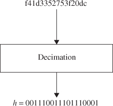
Discard 6 bits from both ends of the 64-bit message digest h and then pick 1 bit every 3 bits by the rule of decimation such that
![]()
Figure 5.4 A 18-bit hash code computation scheme.

Thus, the 128-bit hash code will be
![]()
Figure 5.5 A 128-bit hash code computation using a shift left.


Figure 5.6 A 128-bit hash code computation using inverse operation.
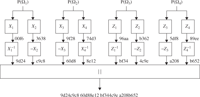
![]()
This is the 128-bit hash code found. So far, we have discussed computation forthe DMDC without appending a 1-bit flag and the message length in hex digits.
Figure 5.7 A 128-bit hash code computation using addition and multiplication.

5.2 Advanced DMDC Algorithm
This section presents the secure DMDC algorithm for providing an acceptable level of security.
5.2.1 Key Schedule
Figure 5.9 shows the newly devised key generation scheme. The 64-bit input key reshapes to the 56-bit key sequence through Table 3.1 (PC-1). The 56-bit keys are loaded into two 28-bit registers (![]() ,
, ![]() ). The contents of these two registers are shifted by the
). The contents of these two registers are shifted by the ![]() and
and ![]() positions to the left.
positions to the left. ![]() and
and ![]() are generated by the state transition function
are generated by the state transition function ![]() shown in Figures 5.8 and 5.8. In Figure 5.8, the 64-bit input key is separated into two 32 bits. Each becomes the input
shown in Figures 5.8 and 5.8. In Figure 5.8, the 64-bit input key is separated into two 32 bits. Each becomes the input ![]() to
to ![]() ).
). ![]() and
and ![]() are computed from
are computed from ![]() (mod 23). LFSR in Figure 5.10 is the device for the generation of a pseudorandom binary sequence (PRBS), whose characteristic function is:
(mod 23). LFSR in Figure 5.10 is the device for the generation of a pseudorandom binary sequence (PRBS), whose characteristic function is:
![]()
The 64-bit input key is assumed to be 7a138b2524af17c5. Using Figure 5.11, entire round keys are computed, as shown in Table 5.2.
Figure 5.8 State transition function ![]() for PRBS generation.
for PRBS generation.

Figure 5.9 The newly devised DMDC key generation scheme.

Figure 5.10 LFSR with the primitive polynomial ![]() for PRBS generation.
for PRBS generation.

Figure 5.11 The new DMDC algorithm for message digest.

Table 5.2 Round key generation corresponding to (![]() ,
, ![]() )
)
| rth round | ( |
|
| 1 | (2, 21) | 36320340397a |
| 2 | (14, 19) | 9394d0aac24c |
| 3 | (0, 15) | 91c2c6fcd01e |
| 4 | (7, 7) | fcf6701c06a4 |
| 5 | (21, 13) | c38496e8c45e |
| 6 | (1, 20) | 12f64d47235d |
| 7 | (7, 17) | 174a16a3c335 |
| 332 | (21, 2) | 17320b413872 |
| 333 | (19, 17) | 9ad8226cd646 |
| 334 | (1, 11) | 961203c1315b |
| 335 | (2, 18) | 125ec46f8a55 |
| 336 | (2, 13) | cd8d4610f0c4 |
| 337 | (19, 9) | 5e40db051358 |
| 338 | (15, 8) | 0414fc86b547 |
5.2.2 Computation of Message Digests
After the input message M of arbitrary length appends padding, divide the padded message into the integer multiple of 128 bits such that ![]() . Each
. Each ![]() again positions to four 32-bit words as:
again positions to four 32-bit words as:
![]()
where ![]() represents the rth round of 128-bit message unit as shown in Figure 5.11. A, B, C, and D denote the four 32-bit buffers in which the data computed at the
represents the rth round of 128-bit message unit as shown in Figure 5.11. A, B, C, and D denote the four 32-bit buffers in which the data computed at the ![]() th round is to be stored. Thus,
th round is to be stored. Thus, ![]() ,
, ![]() ,
, ![]() , and
, and ![]() will become the rth round input data. Notice that the output at each round is swapped such that the data diffusion becomes very effective.
will become the rth round input data. Notice that the output at each round is swapped such that the data diffusion becomes very effective.
The following example demonstrates motivation, so that the reader can understand the whole process at each round (Figure 5.11). The ASCII file structure for the input message is assumed to be as shown below.
| 001: 12345678901234567890 |
| 002: 23456789012345678901 |
| 003: 34567890123456789012 |
| 198: 89012345678901234567 |
| 199: 90123456789012345678 |
| 200: 01234567890123456789 |
After receiving this ASCII file as the input, the 128-bit divided blocks are expressed in hexadecimal notation as follows:

In the last block, the last three words contain padding and message length. The message length is 0xa8b0 (43184 in decimal).
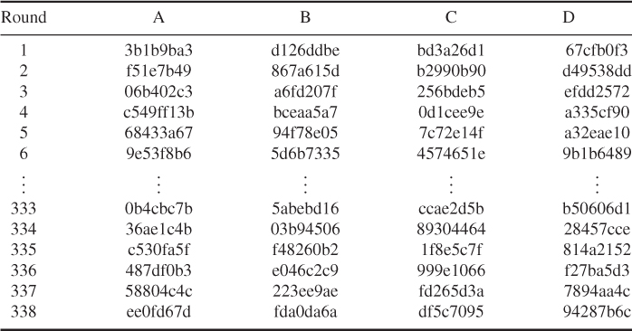
The swapped outputs A, B, C, and D at each round are computed as shown in Table 5.3.
Table 5.3 The swapped output A, B, C, and D at each round
Thus, the hash code computations applied to the new DMDC algorithm are listed in Table 5.4.
Table 5.4 Hash code values based on the new DMDC scheme
| Hash code length | Hash value | |
| 32 Bits | 5f79ee7e | |
| 64 Bits | ad88e2594fe4287a | |
| 18 Bits | 32064 | |
| Using left shift | 07eb3ef78369abf6384aefae850f6d92 | |
| Using inverse | ad88e2594fe4287a392abad213122695 | |
| 128 Bits | ||
| Using addition and | 10c62983026032634cdc8f6b6bd84085 | |
| multiplication | ||
The DMDC algorithm is a secure, compact, and simple hash function. The security of DMDC has never been mathematically proven, but it depends on the problem of F(r) generating the PRBS that makes each 28-bit key (left and right) shift to the left. The secure DMDC processes data sequentially, block-by-block of a 128-bit unit when computing the message digest. The computation uses four working registers labeled A, B, C, and D. These registered contents are the swapped outputs at the end of each round. The four 32-bit input units are XORed with the register contents. This process offers good performance and considerable flexibility.
5.3 MD5 Message-Digest Algorithm
The MD5 message-digest algorithm was developed by Ronald Rivest at the MIT in 1992. This algorithm takes an input message of arbitrary length and produces a 128-bit hash value of the message. The input message is processed in 512-bit blocks which can be divided into sixteen 32-bit sub-blocks. The message digest is a set of four 32-bit blocks, which concatenate to form a single 128-bit hash code. MD5 (1992) is an improved version of MD4, but is slightly slower than MD4 (1990).
The following steps are carried out to compute the message digest of the input message.
5.3.1 Append Padding Bits
The message is padded so that its length (in bits) is congruent to 448 modulo 512; that is, the padded message is just 64 bits short of being a multiple of 512. This padding is formed by appending a single “1” bit to the end of the message, and then “0” bits are appended as needed such that the length (in bits) of the padded message becomes congruent to 448 ![]() , modulo 512.
, modulo 512.
5.3.2 Append Length
A 64-bit representation of the original message length is appended to the result of the previous step. If the original length is greater than ![]() , then only the low-order of 64 bits is used for appending two 32-bit words.
, then only the low-order of 64 bits is used for appending two 32-bit words.
The length of the resulting message is an exact multiple of 512 bits. Equivalently, this message has a length that is an exact multiple of sixteen 32-bit words. Let ![]() denote the word of the resulting message, with N an integer multiple of 16.
denote the word of the resulting message, with N an integer multiple of 16.
5.3.3 Initialize MD Buffer
A four-word buffer represents four 32-bit registers (A, B, C, and D). This 128-bit buffer is used to compute the message digest. These registers are initialized to the following values in hexadecimal (low-order bytes first).
These four variables are then copied into different variables: A as AA, B as BB, C as CC, and D as DD.
5.3.4 Define Four Auxiliary Functions (F, G, H, I)
F, G, H, and I are four basic MD5 functions. Each of these four nonlinear functions takes three 32-bit words as input and produces one 32-bit word as output. They are, one for each round, expressed as:
where ![]() denotes the bitwise AND of X and Y;
denotes the bitwise AND of X and Y; ![]() denotes the bitwise OR of X and Y;
denotes the bitwise OR of X and Y; ![]() denotes the bitwise complement of X, that is, NOT(X); and
denotes the bitwise complement of X, that is, NOT(X); and ![]() denotes the bitwise XOR of X and Y.
denotes the bitwise XOR of X and Y.
These four auxiliary functions are designed in such a way that if the bits of X, Y, and Z are independent and unbiased, then at each bit position the function F acts as a conditional: if X then Y else Z. The functions G, H, and I are similar to thefunction F in that they act in “bitwise parallel” to their product from the bits of X, Y, and Z. Notice that the function H is the bitwise XOR function of its inputs.
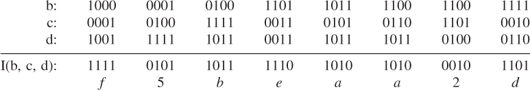
The truth table for the computation of the four nonlinear functions (F, G, H, I) is given in Table 5.5.
Table 5.5 Truth table of four nonlinear functions
| XYZ | FGHI |
| 000 | 0001 |
| 001 | 1010 |
| 010 | 0110 |
| 011 | 1001 |
| 100 | 0011 |
| 101 | 0101 |
| 110 | 1100 |
| 111 | 1110 |
5.3.5 FF, GG, HH, and II Transformations for Rounds 1, 2, 3, and 4
If M[k], ![]() , denotes the kth sub-block of the message, and
, denotes the kth sub-block of the message, and ![]() represents a left shift by s bits, the four operations are defined as follows:
represents a left shift by s bits, the four operations are defined as follows:
Computation uses a 64-element table ![]() ,
, ![]() , which is constructed from the sine function.
, which is constructed from the sine function. ![]() denotes the ith element of the table, which is equal to the integer part of 4294967296 times
denotes the ith element of the table, which is equal to the integer part of 4294967296 times ![]() , where i is in radians.
, where i is in radians.
![]()
where ![]() and
and ![]() .
.
Computation of ![]() for
for ![]() is shown in Table 5.6.
is shown in Table 5.6.
Table 5.6 Computation of ![]() For
For ![]()

5.3.6 Computation of Four Rounds (64 Steps)
Each round consists of 16 operations. Each operation performs a nonlinear function on three of A, B, C, and D. Let us show FF, GG, HH, and II transformations for rounds 1, 2, 3, and 4 in what follows.
Round 1
Let FF[a, b, c, d, ![]() , s, i] denote the operation
, s, i] denote the operation
![]()
Then the following 16 operations are computed.
FF[a, b, c, d, M[0], 7, 1], FF[d, a, b, c, M[1], 12, 2], FF[c, d, a, b, M[2], 17, 3],
FF[b, c, d, a, M[3], 22, 4], FF[a, b, c, d, M[4], 7, 5], FF[d, a, b, c, M[5], 12, 6],
FF[c, d, a, b, M[6], 17, 7], FF[b, c, d, a, M[7], 22, 8], FF[a, b, c, d, M[8], 7, 9],
FF[d, a, b, c, M[9], 12, 10], FF[c, d, a, b, M[10], 17, 11], FF[b, c, d, a, M[11], 22, 12],
FF[a, b, c, d, M[12], 7, 13], FF[d, a, b, c, M[13], 12, 14], FF[c, d, a, b, M[14], 17, 15],
FF[b, c, d, a, M[15], 22, 16]
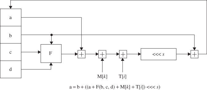
The basic MD5 operation for FF transformations of round 1 is plotted as shown in Figure 5.12. GG, HH, and II transformations for rounds 2, 3, and 4 are similarly sketched.
Figure 5.12 Basic MD5 operation.
Round 2
Let GG[a, b, c, d, ![]() , s, i] denote the operation
, s, i] denote the operation
![]()
Then the following 16 operations are computed.
GG[a, b, c, d, M[1], 5, 17], GG[d, a, b, c, M[6], 9, 18], GG[c, d, a, b, M[11], 14, 19],
GG[b, c, d, a, M[0], 20, 20], GG[a, b, c, d, M[5], 5, 21], GG[d, a, b, c, M[10], 9, 22],
GG[c, d, a, b, M[15], 14, 23], GG[b, c, d, a, M[4], 20, 24], GG[a, b, c, d, M[9], 5, 25],
GG[d, a, b, c, M[14], 9, 26], GG[c, d, a, b, M[3], 14, 27], GG[b, c, d, a, M[8], 20, 28],
GG[a, b, c, d, M[13], 5, 29], GG[d, a, b, c, M[2], 9, 30], GG[c, d, a, b, M[7], 14, 31],
GG[b, c, d, a, M[12], 20, 32],
Round 3
Let HH[a, b, c, d, ![]() ], s, i] denote the operation
], s, i] denote the operation
![]()
Then the following 16 operations are computed.
HH[a, b, c, d, M[5], 4, 33], HH[d, a, b, c, M[8], 11, 34], HH[c, d, a, b, M[11], 16, 35],
HH[b, c, d, a, M[14], 23, 36], HH[a, b, c, d, M[1], 4, 37], HH[d, a, b, c, M[4], 11, 38],
HH[c, d, a, b, M[7], 16, 39], HH[b, c, d, a, M[10], 23, 40], HH[a, b, c, d, M[13], 4, 41],
HH[d, a, b, c, M[0], 11, 42], HH[c, d, a, b, M[3], 16, 43], HH[b, c, d, a, M[6], 23, 44],
HH[a, b, c, d, M[9], 4, 45], HH[d, a, b, c, M[12], 11, 46], HH[c, d, a, b, M[15], 16, 47], HH[b, c, d, a, M[2], 23, 48],
Round 4
Let II[a, b, c, d, ![]() , s, i] denote the operation
, s, i] denote the operation
![]()
Then the following 16 operations are computed.
II[a, b, c, d, M[0], 6, 49], II[d, a, b, c, M[7], 10, 50], II[c, d, a, b, M[14], 15, 51],
II[b, c, d, a, M[5], 21, 52], II[a, b, c, d, M[12], 6, 53], II[d, a, b, c, M[3], 10, 54],
II[c, d, a, b, M[10], 15, 55], II[b, c, d, a, M[1], 21, 56], II[a, b, c, d, M[8], 6, 57],
II[d, a, b, c, M[15], 10, 58], II[c, d, a, b, M[6], 15, 59], II[b, c, d, a, M[13], 21, 60],
II[a, b, c, d, M[4], 6, 61], II[d, a, b, c, M[11], 10, 62], II[c, d, a, b, M[2], 15, 63],
II[b, c, d, a, M[9], 21, 64],
After performing all of the above steps, A, B, C, and D are added to their respective increments AA, BB, CC, and DD, as
![]()
and the algorithm continues with the resulting block of data. The final output is the concatenation of A, B, C, and D.
![]()
The 512-bit padded message is produced from the 152-bit CDMA message by appending the 360-bit padding as shown below.

I. Round 1 Computation for FF[a, b, c, d, ![]() , s, i]
, s, i] ![]()
![]() , where
, where ![]() denotes the 32-bit value obtained by circularly shifting U left by s bit positions.
denotes the 32-bit value obtained by circularly shifting U left by s bit positions.

Compute ![]()
| a: 67452301 |
| F(b, c, d): 98badcfe |
| M[0]: 7a138b25 |
| T[1]: d76aa478 |
| U: 517e2f9c |

Since ![]() denotes the circular shift of U to the left by 7 bits, the shifted U value yields:
denotes the circular shift of U to the left by 7 bits, the shifted U value yields:
| b: efcdab89 |
| U |
| a: aee579b1 |
| d: | 10325476 |
| F[a, b, c]: | bedfadcf |
| M[1]: | 24af17c3 |
| T[2]: | e8c7b756 |
| U: | dc88d15e |
![]()
From ![]() , we have
, we have
| a: aee57961 |
| U |
| d: 3bfb6779 |
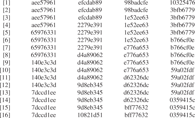
![]()
Let ![]() where
where ![]() ,
, ![]() , c = bff77632,
, c = bff77632, ![]() ,
, ![]() , and
, and ![]() .
.

Compute ![]()
| a: 7dccd1ee |
| G(b, c, d): bca63772 |
| M[1]: 24af17c3 |
| T[17]: f61e2562 |
| V: 55404685 |
| b: 10821d51 |
| V |
| a: b88aedfb |
![]()
Through the 16 operations, GG transformation for round 2 can be accomplished as shown below.

![]()
where ![]() ,
, ![]() ,
, ![]() ,
, ![]() ,
, ![]() ,
, ![]() , and
, and ![]() .
.

Compute ![]()
| a: | 5b8a2ae8 |
| H(b, c, d): | a81d0f01 |
| M[5]: | 00000000 |
| T[33]: | fffa3942 |
| W: | 03a1732b |
| b: 29e29554 |
| W |
| a: 63f9c804 |


![]()
where ![]() ,
, ![]() ,
, ![]() ,
, ![]() ,
, ![]() ,
, ![]() , and
, and ![]() .
.
Compute ![]()
| a: fbc16051 |
| I(b, c, d): f5beaa2d |
| M[0]: 7a138b25 |
| T[49]: f4292244 |
| Z : 5fbcb7e7 |
| b: 814dbccf |
| Z′: ef2df9d7 |
| a: 707bb6a6 |
![]()
The results from the 16 operations are listed in the following.

![]()
The last operation of this transformation is:
![]()
After this, the following additions are finally performed to produce the message digest.
The message digest produced as an output of A, B, C, and D is the concatenation of A, B, C, and D.

In CDMA cellular mobile communications, a shared secret data (SSD) is a 128-bit pattern stored in semipermanent memory in the mobile station. SSD is partitioned into two 64-bit distinct subsets, SSD-A and SSD-B. SSD-A is used to support the authentication process, while SSD-B is used to support voice privacy and message confidentiality.
SSD subsets are generated from the message digest as follows:
| SSD-A: 3bd73d8c145de697 |
| SSD-B: 8c94485550423d7d |
5.4 Secure Hash Algorithm (SHA-1)
The Secure Hash Algorithm (SHA) was developed by the National Institute of Standards and Technology (NIST) for use with the Digital Signature Algorithm (DSA) and published as a Federal Information Processing Standards (FIPS PUB 180) in 1993. The Secure Hash Standard (SHS) specifies an SHA-1 for computing the hash value of a message or a data file. When a message of any length of less than ![]() bits is input, the SHA-1 produces a 160-bit output called a message digest (or a hash code). The message digest can then be input to the DSA, which generates or verifies the signature for the message. Signing the message digest rather than the message often improves the efficiency of the process because the message digest is usually much smaller than the message.
bits is input, the SHA-1 produces a 160-bit output called a message digest (or a hash code). The message digest can then be input to the DSA, which generates or verifies the signature for the message. Signing the message digest rather than the message often improves the efficiency of the process because the message digest is usually much smaller than the message.
The SHA-1 (FIPS 180-1, 1995) is a technical revision of SHA (FIPS 180, 1993). The SHA-1 is secure because it is computationally impossible to find a message which corresponds to a given message digest, or to find two different messages which produce the same message digest. Any change to a message in transit will result in a different message digest, and the signature will fail to verify. The SHA-1 is based on the MD4 message-digest algorithm and its design is closely modeled on that algorithm.
5.4.1 Message Padding
The message padding is provided to make a final padded message a multiple of 512 bits. The SHA-1 sequentially processes blocks of 512 bits when computing the hash value (or message digest) of a message or data file that is provided as input. Padding is exactly the same as in MD5. The following specifies how this padding is performed. As a summary, first append a “1” followed by as many “0s” as necessary to make it 64 bits short of a multiple of 512 bits, and finally, a 64-bit integer is appended to the end of the 0-appended message to produce a final padded message of length ![]() bits. The 64-bit integer “I” represents the length of the original message. Now, the padded message is then processed by the SHA-1 as
bits. The 64-bit integer “I” represents the length of the original message. Now, the padded message is then processed by the SHA-1 as ![]() -bit blocks.
-bit blocks.
![]()
This message has length ![]() . After “1” is appended, we have 01100001 01100010 011000111. The number of bits of this bit string is 25 because
. After “1” is appended, we have 01100001 01100010 011000111. The number of bits of this bit string is 25 because ![]() . Therefore, we should append 423 “0s” and the two-word representation of 24, that is, 00000000 00000018 (in hex), for forming the final padded message as follows:
. Therefore, we should append 423 “0s” and the two-word representation of 24, that is, 00000000 00000018 (in hex), for forming the final padded message as follows:
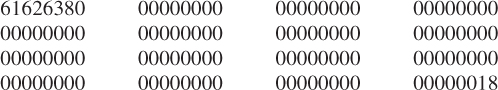
This final padded message consisting of one block contains 16 words ![]() bits for
bits for ![]() in this case.
in this case.
5.4.2 Initialize 160-bit Buffer
The 160-bit buffer consists of five 32-bit registers (A, B, C, D, and E). Before processing any blocks, these registers are initialized to the following hexadecimal values.

Note that the first four values are the same as those used in MD5. The only difference is the use of a different rule for expressing the values, that is, high-order octets first for SHA and low-order octets first for MD5.
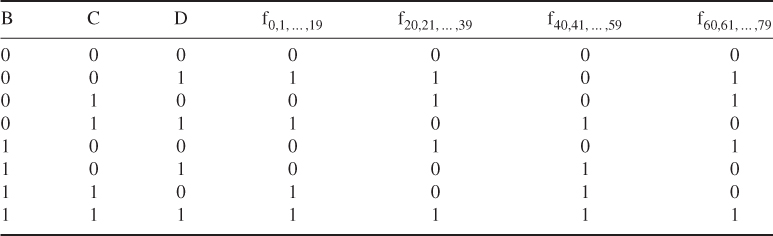
5.4.3 Functions Used
A sequence of logical functions ![]() is used in SHA-1. Each function
is used in SHA-1. Each function ![]() , operates on three 32-bit words B, C, and D and produces a 32-bit word as the output. Each operation performs a nonlinear operation of three of A, B, C, and D and then does shifting and adding as in MD5. The set of SHA primitive functions,
, operates on three 32-bit words B, C, and D and produces a 32-bit word as the output. Each operation performs a nonlinear operation of three of A, B, C, and D and then does shifting and adding as in MD5. The set of SHA primitive functions, ![]() (B, C, D), is defined as follows:
(B, C, D), is defined as follows:

where
As can be seen, only three different functions are used. For ![]() , the function
, the function ![]() acts as a conditional: if B then C else D. For
acts as a conditional: if B then C else D. For ![]() and
and ![]() , the function
, the function ![]() is true if two or three of the arguments are true. Table 5.7 is a truth table of these functions.
is true if two or three of the arguments are true. Table 5.7 is a truth table of these functions.
Table 5.7 Truth table of four nonlinear functions for SHA-1
5.4.4 Constants Used
Four distinct constants are used in SHA-1. In hexadecimal, these values are given by
5.4.5 Computing the Message Digest
The message digest is computed using the final padded message. To generate the message digest, the 16-word blocks (![]() to
to ![]() ) are processed in order. The processing of each
) are processed in order. The processing of each ![]() involves 80 steps; that is, the message block is transformed from sixteen 32-bit words (
involves 80 steps; that is, the message block is transformed from sixteen 32-bit words (![]() to
to ![]() ) to eighty 32-bit words (
) to eighty 32-bit words (![]() to
to ![]() ) using the following algorithm.
) using the following algorithm.
Divide ![]() into 16 words
into 16 words ![]() ,
, ![]()
![]() , where
, where ![]() is the leftmost word. For
is the leftmost word. For ![]() –15,
–15, ![]() . For
. For ![]() –79,
–79, ![]() (
(![]() ).
).
Let ![]() ,
, ![]() ,
, ![]() ,
, ![]() ,
, ![]() . For
. For ![]() –79 do
–79 do

where
After all N 512-bit blocks have been processed, the output from the Nth stage is the 160-bit message digest, represented by the five words ![]() ,
, ![]() ,
, ![]() ,
, ![]() , and
, and ![]() .
.
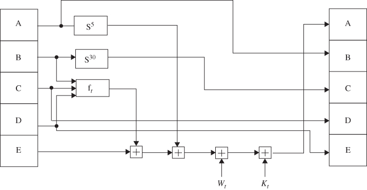
The SHA-1 operation looking at the logic in each of the 80 rounds of one 512-bit block is shown in Figure 5.13.
Figure 5.13 SHA-1 operation.
| t | |
| 0 | |
| 1 | |
| t | |
| 15 | |
| 16 | |
| 17 | |
| 30 | |
| 31 | |
| 59 | |
| 60 | |
| 78 | |
| 79 |

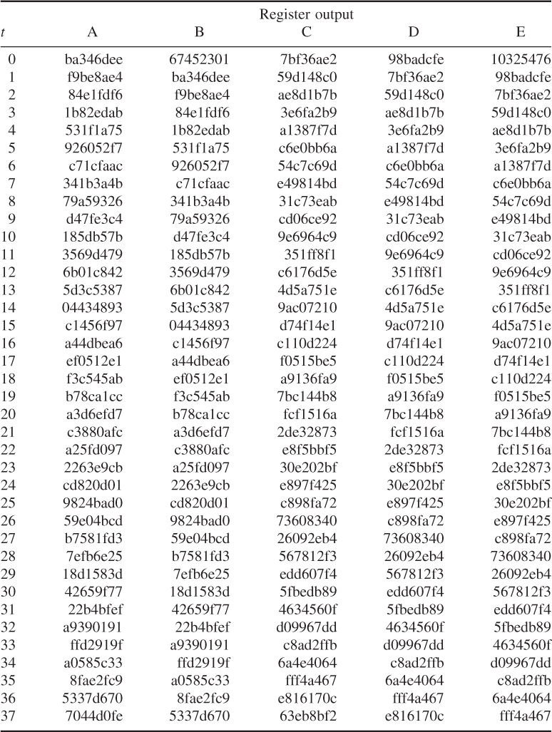
The initial hex values of ![]() are
are

The hex values of A, B, C, D, and E after pass ![]() are computed as follows:
are computed as follows:
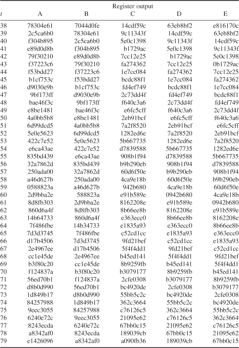
After all 512-bit blocks have been processed, the output represented by the five words, ![]() ,
, ![]() ,
, ![]() ,
, ![]() , and
, and ![]() , is the 160-bit message digest as shown below.
, is the 160-bit message digest as shown below.
The 160-bit message digest is then the data concatenation of ![]() :
:
![]()
As discussed previously, the digitized document or message of any length can create a 160-bit message digest which is produced using the SHA-1 algorithm.
Any change to a digitized message in transit results in a different message digest. In fact, changing a single bit of the data modifies at least half of the resulting digest bits. Furthermore, it is computationally impossible to find two meaningful messages that have the same 160-bit digest. On the other hand, given a 160-bit message digest, it is also impossible to find a meaningful message with that digest.
5.5 Hashed Message Authentication Codes (HMAC)
The keyed-hashed Message Authentication Code (HMAC) is a key-dependent one-way hash function which provides both data integrity and data origin authentication for files sent between two users. HMACs have the same properties as the one-way hash functions discussed earlier in this chapter, but they also include a secret key. HMACs can be used to authenticate data or files between two users (data authentication). They can also be used by a single user to determine whether or not the user's files have been altered (data integrity).
To evaluate HMAC over the message or file, the following expression is required to compute.
![]()
where
The HMAC equation is explained as follows:
Figure 5.14 illustrates the overall operation of HMAC, explaining these steps.
Figure 5.14 Overall operation of HMAC computation using either MD5 or SHA-1 (message length computation is based on ![]() ).
).

Referring to Figure 5.14, the HMAC–SHA-1 calculation proceeds with the steps shown below.


![]()

![]()
The alternative operation for computation of either HMAC-MD5 or HMAC–SHA-1 is based on the following expression.

f denotes a compression function representing either SHA-1 or MD5 hash function.
The procedure can be explained in words as follows:
Figure 5.15 shows the alternative scheme based on these steps.
Figure 5.15 Alternative operation of HMAC computation using MD5 or SHA-1 (message length computation is based on M only).
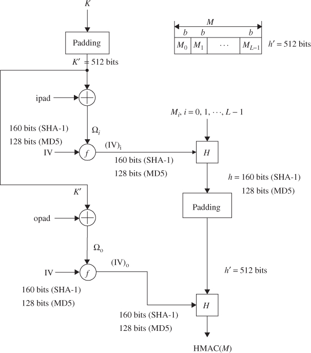
Referring to Figure 5.15, the HMAC–SHA-1 calculation proceeds through the steps shown below.

![]()
![]()


The HMAC is a cryptographic checksum with the highest degree of security against attacks. HMACs are used to exchange information between two parties, where both have knowledge of the secret key. A digital signature does not require any secret key to be verified for authentication.