
The i2c protocol enables us to port a master component (usually the microprocessor) and several slave devices. Several masters can share the same bus, and the same component can send slave status to the master or vice versa. However, communication takes place only between the master and one slave. Note also that the master can send a command to all slaves simultaneously (such as a sleep or reset request).
At the electrical level, the protocol uses signals alternating between high and low levels; the most common value pairs are (0, 5V) and (0, 3.3V). The SCL clock signal is generated by the master. The serial data (SDA) data signal is set high or low by the master or slave, according to the communication phase. Throughout the duration of the high segment of the SCL clock, the SDA data signal must be kept high or low, depending on whether it transmits a 1 or a 0.
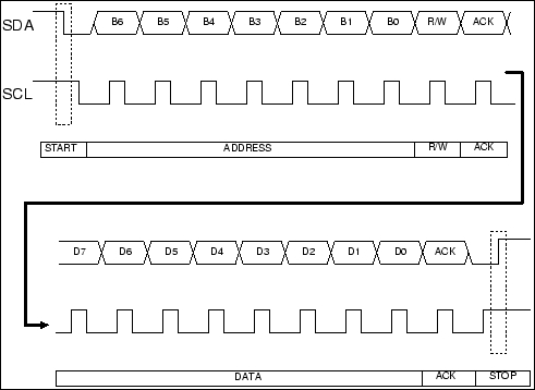
Finally, as shown in the following figure, particular configurations of signals (produced by the master) can indicate the beginning or end of an exchange, which are called the START and STOP conditions. This is a variation of the SDA signal for a slot clock.
In order to test the i2c interface on our Raspberry Pi, we will develop an application to retrieve data from a Wii Nunchuck through the i2c bus.