
CONTENTS
4.3 Ultraviolet Optical Element
4.5.2 Spatial Filter, Spatial Frequency Filter
4.11 Optical Polariscope and Optical Scanner
4.12 Optical Integrated Circuit and Optoelectronic Integrated Circuit
4.19 Vibration Isolation System
Various devices and elements are utilized for the handling of optical elements and the operation of light tuned to a target experiment. With infrared light and ultraviolet light outside the visible light range, some visible light other than the wavelength to be used transmits through it or a special specification for capability to withstand high output is used. Optical elements such as lenses, prisms, and mirrors are not used in naked style, but are handled after being placed in a frame for holding and fixing by suitable means. Articles corresponding to this frame are mounts and holders. An optical bench and a tabletop are used for disposing and fixing the optical element placed in the holder according to the purpose of the experiment, and a vibration isolation stand is used to perform experiments under stable conditions, without being affected by vibrations and other disturbances.
The optical element fixed to the holder constitutes an optical system to meet the purpose of the experiment. Adjustments to the optical system are carried out using a micromotion element and a positioning element so that conditions such as distance, position, inclination, and angle are satisfied while light from a light source is confirmed.
In the optical system, light-related operations, such as strength adjustment of light intensity, taking out of specific wavelength light, and separation of specific wavelength, are performed causing light to pass through the optical system at the required time, blocking the light at the required time, or spatial filtering such as noise component cutting. An attenuator, a filter, and a pinhole are used for these operations. Furthermore, an optical modulator such as an acoustic optical modulator (AOM) and a light deflector become necessary for adjustments of light intensity modulation and deflection angle, and a scanning equipment, such as a galvanometer or a scanner, is used for two-dimensional light operations. For infrared light that is not visible light, adjustments are performed in many cases using visible light in the optical system, and special optical elements for infrared light, such as a lens that has high transmissivity in the infrared region and allows transmission of even visible light, are used. Visible light for adjustments should be used also for ultraviolet light, and in this case, quartz is used for materials of the optical element.
Most materials such as glass and crystal normally used in the visible light region are transparent also in the near-infrared region and are used for lenses, prisms, and window materials. Silica glass can be used up to a wavelength of around 4 μm and even Pyrex can be used up to a wavelength of around 3 μm. In the infrared region of a wavelength longer than that, use of materials such as halide single crystals, oxide single crystals, glass, chalcogenide glass, and semiconductors is necessary. In optical communication, silica-glass fiber, in which the OH-group that is responsible for absorption is reduced as much as possible, is used. In infrared spectrometry where the wavelength region used is broader, a reflecting optical system is used frequently, whereas with a temperature measurement device and an imaging device such as a night-vision device where a wavelength of 3–5 and 8–14 μm, referred to as the window of atmosphere is used primarily, refractive lens employing Ge and Si of the semiconductor is used and achromatizing lens and zoom lens are manufactured to be used.
In infrared spectrometry, optical elements such as prisms, window materials, and cells are necessary, while appropriate materials are selected taking the applicable wavelength limit, workability, deliquescence, and stability into consideration. Halide single crystals are transparent to wavelength ranging from the ultraviolet region to the infrared region. Although MgF2 and CaF2 are stable, their transparency region is up to around 12 μm. The transparency region of NaCl, KBr, and CsI is long—up to 20, 30, and 70 μm, respectively—but these materials need caution in handling due to their deliquescence. In addition, NaCl and KBr exhibit cleavage. The mixed crystal KRS-5 of T1Br and T1I is transparent up to a wavelength of 50 μm and exhibits a little deliquescence. Oxide crystals (e.g., sapphire) are thermally and chemically stable, and their transparency region is from ultraviolet light to a wavelength of around 7 μm. The refraction factor is from about 1.5 to 2.0. Chalcogenide glass such as Ge10As20Te70 is transparent in wavelength range of 1–20 μm, has excellent chemical stability, and is used as the infrared transmission fiber. The refraction factor is as high as 2.5–3.0. In addition, an interference filter using a dielectric body multilayer film and a diffracting grating using a metallic mesh are used (Figure 4.1).
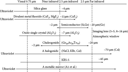
FIGURE 4.1 Infrared optical elements and materials in a wavelength range.
4.3 ULTRAVIOLET OPTICAL ELEMENT
With ordinary optical glasses, with wavelength less than about 350 nm, transmissivity is reduced and cannot be used for long. Therefore in the ultraviolet region, as materials for lens and prisms, silica glass (quartz), Al2O3 (sapphire), CaF2 (fluorite), halide such as MgF2, and LiF are used. The shortest wavelength of these materials in the transparent region is about 160, 150, 125, 115, and 105 nm, respectively. Due care should be given, if a strong ultraviolet light is irradiated to silica glass or LiF because defects such as color center are generated, thereby reducing the transmissivity (solarization). Performances of silica glass have improved; LiF exhibits a slight deliquescence.
For optical elements used in the ultraviolet region, reducing lens for lithography is mentioned. For window materials of the resonator of KrF excimer laser (wavelength 248 nm), ArF excimer laser (wavelength 193 nm), and F2 excimer laser (wavelength 157 nm) as the light source, halide crystal is used, while silica glass is used for reducing lens due to the homogeneity of the refraction factor and distortion-related problems. Since chromatic aberration correction is not possible with a single glassy material, several plans are proposed including an excimer laser of a plateau with a narrower band made by etalon, prism, and diffracting grid and combination with a mirror optical system. Among ultraviolet regions, in the vacuum ultraviolet region with a wavelength less than 200 nm, circumstances are significantly different. Since an absorption band, referred to as the Schmann region (wavelength 120–190 nm) due to oxygen molecule, is present, the optical system is placed in vacuum where handling of the optical system becomes troublesome. In some cases, replacement by He gas and the like is possible, though this depends on the intended application. In addition, direct incident reflection of a metal rarely takes place with wavelength less than 40 nm, where some new ideas should be used (see Section 4.4).
For a deflection element, Wollaston prism has been produced using MgF2 that has birefringence or synthetic quartz as the base material. Although filters are produced by fixing metallic thin films on the metallic gauze, filters are easily broken and therefore, due care should be given. A diffracting grid is used for the spectroscope of the vacuum ultraviolet application, while an oblique incidence-type grid (such as a runner-type diffracting grid) using total reflection is used in the wavelength region less than 50 nm.
X-ray has a short wavelength and the refraction factor is nearly 1 for every substance; therefore, optical elements that are used under ordinary visible light cannot be used. Normally, spectral elements using Bragg reflection by a single crystal are used. Suppose that the grid interval of the crystal is represented by d, the oblique incidence angle to x-ray crystal (angle from crystal plane) by θ, wavelength by λ, and when nλ = 2d sin θ (n is integer) is satisfied, a diffraction light can obtain a reinforcing reflection. Further, an x-ray filter is available, which is made of a thin film for selecting character x-ray from x-rays generated in x-ray tubes. Of elements that have been attracting attention currently, an optical element that is able to reflect x-ray or to form an image in the wavelength region referred to as soft x-ray (wavelength several 1/10 ~ several tens nm) is mentioned. Since the refraction factor of substances in the soft x-ray region is slightly smaller than 1, contrary to visible light, total reflection is caused when soft x-ray is incident to substances. However, since there is absorption, 100% reflectance is not obtained as observed with visible light. Figure 4.2a shows a representative Wolter-type optical system. This system consists of a hyperboloid of revolution in which one focal point is shared and an ellipsoid of revolution (or paraboloid of revolution). Since incidence to a mirror surface should be made with an extremely small oblique incidence angle, an imaging system with a large numerical aperture is not produced, but chromatic aberration is less and this optical system can be used in a broader wavelength region. Furthermore, the light from an x-ray light source of continuous wavelength can be used effectively.
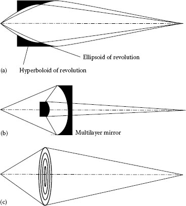
FIGURE 4.2 Soft x-ray imaging element: (a) Wolter type, (b) Schwarzchild type, and (c) Fresnel zone plate.
There is a multilayer film optical system in which substances each having different optical constants are laminated in several tens to several hundred layers to increase reflectance. Use of a multilayer film enables construction of a direct incident optical system, and an optical system with excellent resolving power and broader field of vision can be realized. As for the reflection characteristic of a multilayer mirror, although reflectance as high as several tens of percent is obtained with a wavelength of more than 13 nm, reflectance remains less than 20% with a short wavelength less than that. At present, practical application of an x-ray exposure device has been promoted and a higher efficiency light focusing method has been investigated. Figure 4.2b shows a representative Schwarzschild type. However, with an element of this type, the wavelength of soft x-ray is short, film thickness becomes thin, and interfacial roughness of the multilayer film is not negligible compared to wavelength, and therefore, realization of a multilayer film optical system with a short wavelength is difficult. Deflection elements using a multilayer film and a beam splitter have also been developed.
A Fresnel zone plate that is a diffracting grid in concentric shape is also used as the imaging element (Figure 4.2c). Because this plate has a chromatic aberration, monochromaticity is required for the x-ray to be incident. The resolving power of the zone plate is nearly equal to the width of the outermost shell zone and does not depend on the wavelength. This plate has such features that the resolving power of several tens of nanometers is obtained by an electron beam drawing device and lithography technology and utilization down to a relatively shorter wavelength of several nanometers is possible.
A filter is a component that is provided in an optical path and extracts, enhances, or weakens specific components of light or image as needed and causes the components to pass through.
The photographic filter is designed so that its transmissivity changes primarily according to the wavelength of the light. As typical optical filters, ultraviolet protection filter, infrared protection filter, color conversion filter, chromatic compensation filter, short-wavelength light sharp cut filter, and beam attenuator filter are mentioned. The primary object of these filters is to remove light undesirable for obtaining an image or to allow analysis by only a required wavelength.
A deflection filter that selectively passes straight deflection in a particular direction is also used for removal of light reflected by a surface, such as an aqueous surface or a glass surface. Normally, single-lens reflex cameras and video cameras are equipped with a filter mounting section of threaded type at the front frame of the photographing lens.
4.5.2 SPATIAL FILTER, SPATIAL FREQUENCY FILTER
A spatial or spatial frequency filter is an optical component that is provided on the image surface and has a predetermined transmissivity distribution. Filters in which a 100% transmission part and an absorption part are provided alternately and one in which transmissivity changes in sinusoidal wave fashion are available, and they are used for extraction of features of an image or detection of movements. A filter in which a spatial filter is provided in optical Fourier transform plane is referred to as spatial frequency filter, which is used for noise elimination from image, correction, feature extraction, and accentuation and is effective for image processing and analysis (Figure 4.3).
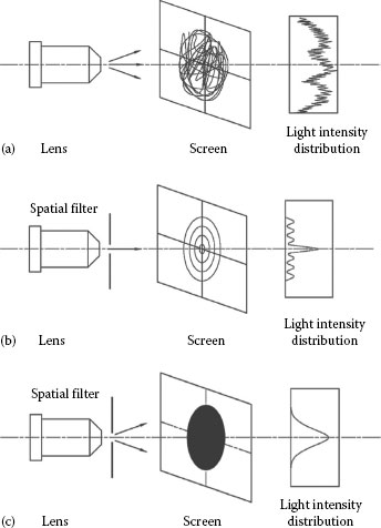
FIGURE 4.3 Functions of spatial filter: (a) without spatial filter, (b) spatial filter under adjustment, and (c) with spatial filter completely adjusted.
A pinhole is an optical component produced such that a small hole for passing light is drilled to an optically opaque substrate. The following pinholes are mentioned according to the application:
1. A component used in the optical system using a laser for elimination of unnecessary optical noises (interference stripes or speckle patterns caused in the luminous flux). This is marketed as “pinhole centering device” being disposed at the position where laser light is focused by microscope lens in combination with a micromotion device in three-dimensional directions. In this case, this device is referred to as a spatial filter.
2. Used in combination with a dark box to obtain images. This is used for “camera obscura” (an old painting device) in which such a phenomenon is used that, from a hole drilled to the wall of a dark room, the outside landscape is reflected to the opposite wall. A pinhole camera in which photographic sensitive material is disposed in the dark box has come into practical use. As for the size of the pinhole, there is an optimum diameter with regard to the blurring of image due to diffraction and geometric optics balance.
3. A small hole provided to the dark box constituting the camera to allow passing of light. This results in light trailing of the camera or photographic fog of the film. This sort of trouble occurs frequently with folding-type camera with bellows.
An element inserted in the optical path of an optical device, which controls the state of the light arbitrarily, may be referred to as a light control device. In particular, this is meant in many cases by the element that is able to change a controlled variable by adding a certain operation from the outside. For operations from the outside, electric field, magnetic field, sound (ultrasonic sound), and the like are used. In addition, in some cases, the controlled variable is regulated by exchanging a plurality of elements. The light control device includes, in addition to various optical components, a diffracting grid, an optical crystal, and a liquid crystal. Also, an optical shutter for controlling laser oscillation in a Q-switched laser may also be considered as a type of light control device. As an optical shutter for Q-switch, spin mirror and the like were used in conventional technology, whereas in recent years, acousto-optic elements are used. Characteristics of the light to be controlled are light volume, direction of light traveling, frequency, phase, in-plane light volume distribution, spectroscopic energy distribution, and deflection. If attention is given to target the modulation component such as the light volume and deflection angle, it is handled as another type of element even if it is the same element. As an example of such elements, an acousto-optic element is taken into consideration. In the acousto-optic element, an ultrasonic planar wave goes straight into the medium and allows a laser light to be incident to a diffracting grid generated three dimensionally corresponding to a crude wave of the sound. If attention is given to this, the straight light volume of laser is reduced, and the element concerned may be used as the attenuator. Moreover, if the fact that the light volume of primary diffraction light changes according to the intensity of the ultrasonic wave in the medium is utilized, the element is used as the optical modulator. In addition, because the deflection angle of the diffraction light changes according to the changes in frequency of ultrasonic wave (pitch of the diffracting grid), it is used as the light deflector. Also, if the fact that the frequency of the diffraction light changes as much as the frequency of ultrasonic wave is applied, it may be used as the light control device for frequency shift or phase creation.
The optical modulator means an optical element that controls light volume, phase, and polarization state by a signal given from the outside. With liquid crystal or optical crystal, the polarization state or phase of the light to be injected changes with the electric field applied (voltage applied across electrodes). It is also possible to change the light volume by disposing an appropriate polarization filter at the incident side and the injection side. With an acousto-optic element, the distribution of the refraction factor generated by traveling of an ultrasonic wave forms a diffracting grid in the medium. Phase modulation or frequency shift is caused to the light injected from here, and light intensity modulation can be performed by changing the frequency of the ultrasonic wave.
An optical element in which optical modulators are disposed in two-dimensional fashion is referred to as a spatial light modulator (SLM) and is used for liquid crystal televisions and projectors. Historically, the concept originated in two-dimensional arrangement of a Kerr cell in the 1910s. Realization of television was attempted through parallel arrangement of signal lines from selenium photoelectric conversion elements being arranged in two-dimensional fashion on an image face of the imaging optical system. Today, liquid crystal and DMD (digital mirror device) type are used as the SLM, while speeding up of light response time and higher performances are sought with recent techniques and development in optical information and optical communication fields.
An optical fiber is an optical component that uses the fact that light, being incident to one end of a transparent optical component, is output from the other end at high efficiency after total reflection or refraction are repeated inside. This is used for transmission and image transmission in information communication and energy fields. Optical fibers are classified as shown in Table 4.1, according to constituent materials, distribution of refraction factor, and propagation mode.
TABLE 4.1
Classification of Optical Fibers
Classification by constituent materials |
Silica-based glass optical fiber (SiO2 + Ge, B, F) Multicomponent-based glass optical fiber (SiO2 + B2O3 + Na2O + ···) Plastic optical fiber (PMMA and others: for short-distance application) Glass fluoride optical fiber (Ultralow loss at λ = 3 μm) |
Classification by propagation mode |
Single-mode optical fiber (Type SM) Multimode optical fiber (Type MM) |
Classification by distribution of refraction factor |
Step-index optical fiber (Type SI) Graded-index optical fiber (Type GI) |
Figure 4.4 shows different conditions of light propagation depending on types of optical fibers. With a step-index-type optical fiber, light is propagated by repeating total reflection at the interface of high-refraction factor core part and low-refraction factor clad part. With graded-index-type optical fiber, light is propagated with smooth meandering according to the distribution of the refraction factor. Although an arbitrary number of optical paths can be set from geometric optics viewpoint, only one with the same phase as the first light is present in one cycle of reflection or meandering in the optical fiber, due to the relationship with the interference with light, and is transmitted. This is referred to as optical fiber mode. With a multimode optical fiber, since the propagation rate is different in every mode, light being incident to the input end becomes a timewise expanded pulse at the output end due to the time difference for every mode. In the meantime, with single-mode-type optical fiber, transmission of a large amount of signals is possible because there is no modal dispersion. Further, optical fibers with a hole inside, referred to as holey fibers, are available to be used for large-capacity and long-distance transmission. Typical dimensions of the optical fiber are core diameter 50 μm/clad and outside diameter 125 μm for multimode and core diameter 10 μm/clad and outside diameter 125 μm for single mode. When the optical fiber is used for optical path of the interferometer, single-mode optical fiber is used because light with single phase is handled.
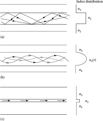
FIGURE 4.4 Propagation of light through optical fiber: (a) optical fiber of step-index type (multimode), (b) optical fiber of graded-index type (multimode), and (c) optical fiber of single-mode type (single mode).
With a step-index-type optical fiber, when core diameter is made large and the difference of the refraction factor between core and clad is made large, light being incident from wider angle in a wider area can be taken in efficiently. Plastic optical fiber used for short-distance information transmission is designed as mentioned. A step-index-type optical fiber is also used in optical fibers for illumination light. When step-index-type optical fibers are arranged regularly in two-dimensional fashion, an image that is incident to one end can be conveyed exactly to other end. A bundle of flexible optical fibers is used in endoscopes for medical and industrial use. Furthermore, an optical fiber faceplate in which a bundle of optical fibers is fixed in plate shape is used for image transmission.
4.11 OPTICAL POLARISCOPE AND OPTICAL SCANNER
An optical component that changes the direction of light traveling is referred to as an optical polariscope or optical scanner. The principle of light deflection is classified as follows:
1. Light reflection: Law of light reflection is used. Because the incident angle and reflection angle are identical, when the reflection plane is turned by angle θ, the direction of reflection light changes as much as 2θ. A galvano-mirror and polygon mirror are mentioned as the optical polariscopes using this principle and are used for laser printers and scanners.
2. Refraction of light: When light is incident to a prism, the direction of traveling of injection light changes according to the apex angle and the refraction factor of the prism. Pentaprism provided in the finder of the single-lens reflex camera and Porro prism for correction of images of the binocular are examples.
3. Diffraction of light: When the grid pitch of the diffracting grid is changed, the direction of travel of diffraction light is changed. With an ultrasonic wave optical polariscope using acousto-optic effects, the grid pitch is changed by changing the frequency of the ultrasonic wave, thereby performing light deflection.
4.12 OPTICAL INTEGRATED CIRCUIT AND OPTOELECTRONIC INTEGRATED CIRCUIT
This is a component with such a construction that optical circuit elements performing transmission and treatment of optical signal are integrated on a single substrate such as a dielectric crystal, in analogous fashion of ordinary IC (integrated circuit), in which electric elements are integrated on a single substrate such as silicon. With this component, a signal is generated, transmitted, and treated in the original form of light.
For optical circuit elements used for light IC, laser light source, light detector, modulator (intensity or phase), polariscope, optical mode converter, and the like are mentioned in addition to waveguide, lens, diffracting grid, branching filter, mode separator, and modal synthesizer.
Compared to conventional optical instruments using individual optical element such as lenses, prisms, shutters, and the like, features of this component are small-sized, lightweight, stable, and have quick response. This component is distinguished from OEIC (optoelectronic integrated circuit), which processes and transmits a light signal after converting it to an electrical signal. OEIC is an integrated circuit on which optical semiconductor elements and electric semiconductor elements are integrated on the same semiconductor substrate and are associated with each other. In the OEIC, the electronic circuit portion excels at signal logic operation and high-speed access memory functions and light circuit portion excels at signal transmission, high-speed processing, and image input/output functions. A new function is realized by combining these features.
These components are largely classified into those in which luminous element such as semiconductor laser and field-effect transistor for driving it are integrated and those in which a light receiving element such as photodiode and field-effect transistor for amplification and signal processing are integrated (charge-coupled device (CCD), etc.). The primary application is transmission and receiving of optical communication. Compound semiconductors such as gallium–arsenic and indium–phosphorous and mixed crystals have been attracting attention as a material.
An attenuator is a device provided in an optical path to be used for adjustments of light volume (attenuation device). This device is capable of maintaining the quality of light. Various types are available, which include a type where an optical wedge with changing transmissivity depending on positions is moved mechanically for adjustments, a type in which light volume is regulated using light modulation element by liquid crystal or crystal, and a type in which regulation is performed using light volume loss in the optical waveguide or optical fiber.
A shutter is an optical device disposed in an optical path to shift transmission and isolation of light. In general, a shutter that has a mechanical construction is referred to as a mechanical shutter; one that has an electrical construction as represented by Kerr cell and liquid crystal is referred to as an electrical shutter; one that controls the exposure time of imaging element as represented by CCD and complementary metal-oxide semiconductor directly and electrically to realize shutter function is referred to as an electronic shutter. Ways of discrimination between electric shutter, electronic shutter, and electrically controlled mechanical shutter are diverse depending on the purpose intended, and they are frequently mixed up.
A camera shutter is used to impart appropriate exposure to photosensitive materials or imaging element. A camera shutter disposed in the vicinity of lens is referred to as lens shutter; one that is disposed in the vicinity of image formation is referred to as focal plane shutter.
An array in which a liquid crystal shutter, a Lanthanum-modified lead zirconate Titanate (PLZT) shutter, or the like is disposed in one-dimensional or two-dimensional fashion is referred to as a shutter array. When image formation is made on a member with photosensitivity through imaging optics, a printer can be realized. Further, a combination of back light and two-dimensional liquid crystal shutter enables the creation of liquid crystal display.
Mechanism element is normally referred to as a stage (Figure 4.5) and is used for movement and positioning in horizontal (X · Y), vertical (Z), rotation (θ), and tilted directions. For stage guiding method, dovetail mechanism, hard steel wire and steel ball, V-groove rail and steel ball, V-groove rail and cross roller, ball bush, ball way, rotation bearing, and the like are mentioned, and selection is made depending on load, movement amount, movement direction, and accuracy.
1. Dovetail mechanism: Used for guiding of sliding contact instead of rolling contact and suited for guiding of a stage for mere positioning, which does not need good accuracy.
2. Hard steel wire and steel ball: Suited for guiding of light-load stage, which does not need high-accuracy positioning.
3. V-groove rail and steel ball: Suited primarily for guiding of high-accuracy light-load precision positioning stage.
4. V-groove rail and cross roller: Equipped with high load capacity for up/down and transverse loads and suited for guiding of high-accuracy heavy-load precision positioning stage.
5. Ball bush: Equipped with precision shaft and ball slide bearing as the rail track stand and therefore, a relatively longer stroke is made possible. Suited for simplified type and lightload stage.
6. Ball way: Equipped with rail track stand and circulating type bearing and therefore, suited for guiding of long-stroke, heavy-load, and relatively high-precision positioning stage.
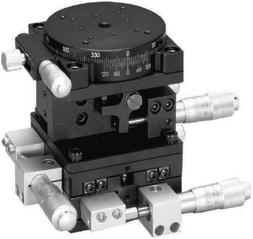
FIGURE 4.5 Stages with translation and rotation. (Courtesy of Chuo Precision Industrial, Tokyo, Japan.)
For movement mechanism, rack and pinion, worm gear, micrometer head, PZT element, micromotor (DC motor), stepping motor, and linear motor are used.
Used for holding laser, shutter, optical accessories such as aperture, and optical elements such as lenses, mirrors, and prisms. Many are designed to be disposed on an optical tabletop using a magnetic stand by providing a shaft with diameter of 12 or 20 mm at the lower part (Figure 4.6). In many cases, the mount is equipped with a mechanism for adjusting the angle of the component to be held in horizontal and vertical directions. The direction of light traveling can be manipulated or adjusted by adjusting the component angle. For fixing of the optical element, the following methods are used: (1) direct adhesion to holder, (2) element pressed against holder using presser ring, (3) fixing by V-groove and presser, and (4) element supported by three supporting bars at three points. As for angle adjustment mechanism, lever type, plate spring, and gimbal type are available. Fine screw thread and micrometer head are used for angle adjustments. Electrically driven micrometer head is used when remote operation is required.
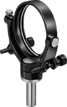
FIGURE 4.6 Mirror mount. (Courtesy of Chuo Precision Industrial, Tokyo, Japan.)
An optical bench is a support bed used in combination with a carrier that can be slid and fixed on the rail fixed to the tabletop at an arbitrary position in the optical axis direction for optical performance experiments. Experiments can be performed while optical elements such as lens and filter are disposed on the straight line.
As for profiles of the optical bench, triangle type, X-type, and Y-type are available. Triangle type has been used conventionally and has an optical element straddled across the optical bench through the carrier, and therefore, positional repeatability after mounting and dismounting, and stability are good. If a scale is mounted to the side face of the rail and reading of the scale is taken from the carrier, this reading can be used for position adjustment and measurements.
X-type has the same sectional profile as that of the prototype meter, has high rigidity, and is capable of corresponding to a longer size article (Figure 4.7). For materials, aluminum alloy is mainly used, contributing to the lightweight feature. The carrier can be fixed to the side face and the upper face, allowing two-dimensional or three-dimensional combination.
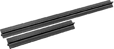
FIGURE 4.7 X-type rail. (Courtesy of Chuo Precision Industrial, Tokyo, Japan.)
Triangle type and X-type optical benches are fixed using a dedicated stand or mount. Y-type has such a profile that X-type rail is halved, which allows reduction in height of the optical axis and direct mounting to the tabletop.
The carrier for disposing the optical element on the rail is fixed by pressing the fixing screw provided to the carrier side face against the rail side face. A holder for optical elements and screw holes for fixing the micromotion mechanism for optical axis adjustment are provided in a carrier (Figure 4.8).
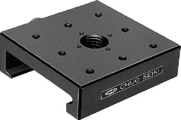
FIGURE 4.8 X-type rail carrier. (Courtesy of Chuo Precision Industrial, Tokyo, Japan.)
As an optical system to be disposed on the straight line, the optical bench is used for Fourier transform optical system, focal length measurement, and photoelasticity.
A base upper face of a tabletop is a precision planar surface, and this is used as the reference surface for various experiments (Figure 4.9). This is used for many optical experiments in addition to precision measurements. The features required are the flatness of the tabletop surface should be satisfactory for stable arrangement and fixing of the optical element; rigidity should be high enough to prevent positional displacement of the optical element being fixed; tabletop itself does not act as the vibration source due to vibration exerted to the tabletop from the outside; and attenuation of the tabletop is satisfactory against vibration exerted. If mark-off lines in grid pattern are marked on the tabletop surface, they are conveniently used in positioning of the optical element.
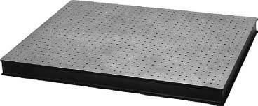
FIGURE 4.9 Optical tabletop. (Courtesy of Chuo Precision Industrial, Tokyo, Japan.)
For the tabletop, stone materials (granite, etc.), cast iron, aluminum alloy casting, and steel materials are used. Although advantages of stone material are good surface flatness, good electrical insulation properties, and high thermal capacity, this material is nonmagnetic and therefore, fixing of the optical element using a magnetic base is not possible. Another disadvantage is that processing of screw holes is difficult. Cast iron is manufactured by casting. Although deformation due to cooling after manufacturing is a problem, no distortion is caused if sufficient annealing is provided at production. However, dust proof processing is required. Aluminum alloy casting is light in weight and drilling of screw holes is easy, while flatness is slightly poor since the surface remains as machine finished. As for steel materials, the steel plate is pasted to the upper and lower faces of the honeycomb structure. A stainless steel plate (SUS430) that has magnetism and is hardly rusted is used for the upper faceplate to allow use of magnetic base, while steel honeycomb core or aluminum honeycomb core is used for the core of honeycomb structure. In case magnetism is not desirable, a stainless steel plate (SUS403) that is nonmagnetic is used. With honeycomb structure, hexagonal cores are closely bonded to form a honeycomb profile, and high rigidity is maintained though light in weight. However, flatness is slightly deteriorated.
Tabletop is not used solely, but optical elements are fixed onto it to be used for various optical experiments, and in many cases, tabletop is mounted on the vibration isolation stand to reduce influences of vibrations from the floor face.
4.19 VIBRATION ISOLATION SYSTEM
A vibration isolation system is used to perform optical experiments in a stable manner avoiding vibrations from the floor face or is used to attenuate vibrations conveyed to the optical element or tabletop. Though the vibration isolation system is used to prevent vibrations to the tabletop or optical element fixed to the table plate surface as much as possible, it is not able to reduce vibrations to zero level. The principle of vibration isolation is explained by the vibration system based on springs in such a way that for vibration frequency f of the vibration system exerted from the outside such as floor vibration, the smaller the vibration frequency fn of the vibration isolation system including optical element and tabletop, and the greater the f/fn, the better vibration isolation effects are obtained. If vibration frequency f of the vibration system is equal to vibration frequency fn of the vibration isolation system, vibration increases due to resonance, and stable experiments are not possible. Vibrations caused from the floor face are in more than a vibration region of 2–4 Hz, and almost all vibration energy is concentrated in 5–15 Hz. For this reason, to develop vibration isolation effects, the frequency fn of the vibration isolation system including the vibration isolation stand (Figure 4.10) should be in a range of less than 1–3 Hz, which is lower than the frequency region of the vibration caused from the floor face.
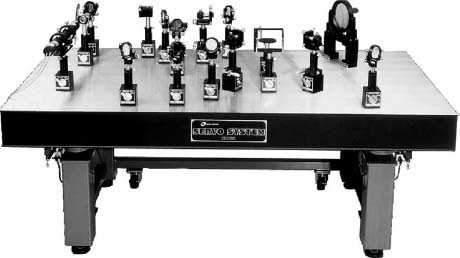
FIGURE 4.10 Optical table consisting of vibration isolator and bread board with optical arrangement for holography. (Courtesy of Chuo Precision Industrial, Tokyo, Japan.)
Many of the vibration isolation systems employ a pneumatic spring for vibration isolation. The pneumatic spring has an airflow restriction mechanism by a small throttle or an orifice in a sealed tank provided to the leg part of the vibration isolation stand. When a displacement is caused in the vertical direction due to vibrations from the floor face, the orifice in the sealed tank and air in the tank partitioned by the orifice serve as a spring, thereby absorbing and attenuating the vibrations. The mass of the tabletop and optical element is supported with a metallic receiver by pneumatic pressure in the tank. Accordingly, the pneumatic spring needs a pneumatic source. In addition, an automatic pressure regulating mechanism for correcting tilting of the tabletop due to mass of the optical element mounted and a regulator for pressure of the air supplied are added.
In order to suppress the resonance phenomenon or to shorten vibration attenuation time, a vibration sensor and position variation sensor are mounted on the vibration isolation stand or floor, and vibrations and position variations are detected and fed back to the vibration isolation mechanism, thereby obtaining significant vibration isolation effects. This component is used for observation of interference and minute structure, device for processing, and optical system.
A fine-pitch screw or micrometer head are used for a micromotion element (Figure 4.11). The principle of the micrometer is such that displacement of a length is enlarged by the rotational angle of the screw and diameter of the thimble, and the construction used is such that the male screw cut to the spindle is engaged with the female screw fixed to the frame (Figure 4.12).
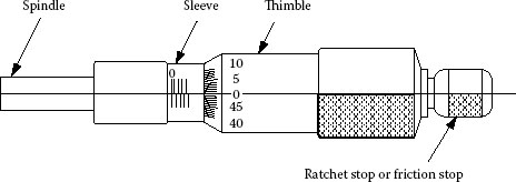
FIGURE 4.11 Micrometer head.
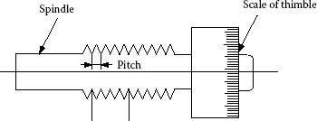
FIGURE 4.12 Screw inside micrometer.
Suppose that the spindle turns angle α and measurement end of the spindle then moves X (mm), a relationship represented by X = Pα/2π (P, pitch of screw [mm]; α, rotational angle of screw [rad]) is established between X and α. If the pitch is made small, the amount of movement of one turning of the spindle becomes small, and the same movement can be expressed by a large angle, which results in increased accuracy. Even if the rotational angle is the same, if the radius of a graduated cylinder (thimble) is made large, the width of the graduation is widened, and it improves the accuracy. The pitch of screw of an ordinary micrometer is 0.5 mm, and less than that is divided into 50 equal parts in circumferential direction while the minimum scale is set to be 0.01 mm. Pitch of screw of a fine micrometer is 0.1 mm and the minimum scale is set to be 0.002 mm. In addition, as micrometers with special mechanism, a micrometer with vernier that ensures better sensitivity and accuracy than those of ordinary ones, differential micrometer, micrometer with dial gauge, micrometer with numerical scale, micron micrometer, and digital micrometer are mentioned.
For positioning elements, piezoelectric element (PZT element), micromotor (DC coreless motor), and stepping motor are mentioned. Piezoelectric element is an element that generates a voltage when a stress is applied and generates a strain when a voltage is applied (piezoelectric effect), and denotes a certain crystal material. Several substances found through nature also exhibit such phenomena, while the material of the piezoelectric element used at present is multicrystal ceramics such as lead zirconium titanate (PZT) (Figure 4.13). With conventional piezoelectric element, a linear displacement of several hundred micrometers is obtained if a voltage is supplied. The actual amount of displacement depends on the materials themselves constituting an actuator, number of layers of materials, and voltage supplied to each layer. Piezoelectric element is capable of responding to a voltage with time constant of a microsecond unit and its displacement resolution is restricted by noises of the electrical supply source. In addition, since a piezoelectric element involves hysteresis effects (Figure 4.14) at actuation, it is not possible to perform linear motion thoroughly. However, in recent years, a piezoelectric element that has a strain gauge at its body has appeared. High linearity driving is now possible if feedback control of the position is carried out using such a sensor. When the stage is driven using a piezoelectric element, the simplest structure is micromotion/coarse motion composite mechanism in which a micrometer head is used for coarse motions and piezoelectric element is used for micromotions. As representative of the stage using a plurality of piezoelectric elements, inchworm motion mechanism is mentioned. A micromotor is a low-output precision motor that uses a permanent magnet for the stator, and many are of coreless construction. For example, a DC coreless motor that is one type of micromotor has the following features:
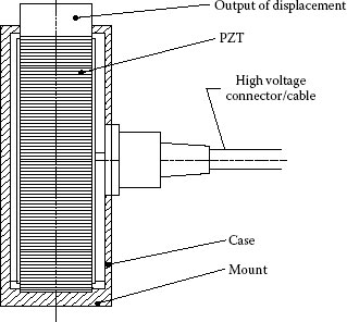
FIGURE 4.13 Construction of piezoelectric element for positioning.
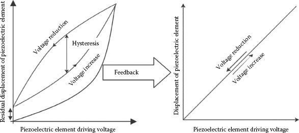
FIGURE 4.14 Hysteresis effects in driving piezoelectric element.
1. Housing structure consists of a magnetic shield.
2. Low-noise and longer service life are possible by adoption of precious metal brush.
3. Electric noises are low (some models incorporate a noise killer).
When the micromotor is used as the positioning element, two methods are available. One is to push out the spindle through the gear in a similar manner as the micromotor head for positioning, and the other is to perform direct positioning by the gear. In addition, positioning accuracy can be improved with the use of an encoder.
Stepping motors are used widely as the positioning element thanks to their features as enumerated below.
1. Because turns are synchronized in a stepwise fashion with the input pulse, high moving resolution is obtained easily when built into a machine.
2. High-precision positioning is possible with open loop.
3. Response at starting and stopping is excellent.
4. Angular error at stopping is not accumulated.
5. High torque is obtained at low-speed operation.
6. Construction of motor is simple allowing ease of maintenance.
7. Suited for mass production because motors can be procured at inexpensive price.
The stepping motor has a big retaining power even at stopping and is able to maintain stop position without depending on a mechanical brake. When a stage is driven using the stepping motor, the feed screw is turned through coupling. Moving resolution of the stage at this point is determined by pitch of the feed screw and rotational resolution of the motor. In recent years, however, resolution is made small using electrical microstepping.
Calibration is used primarily for sensitivity calibration and performance tests as the reference of measurements of measurement equipment or those of test equipment. Normally, small-shaped or small-type standard* and reference instruments† are referred to as calibration specimen. Further, an optical flat is used frequently as the flatness and straightness measurement calibration specimen, and a block gauge or a step gauge is used as step measurement calibration specimen. Typical calibration specimen includes the following:
1. Calibration specimen for sensing pin-type surface roughness measurement machine: Calibration specimen for calibration of indication of surface roughness measurement machine or longitudinal magnification. Shape, scattering of surface roughness, and indication of surface roughness (Ra or Rz) are defined.
2. Standard for calibration of roundness measurement machine: A cylindrical instrument with one or more than one small planar surface or curved surface on the outer circumference to give dynamic and constant displacement to a probe.
3. Calibration specimen for rotational accuracy inspection of roundness measurement machine: A standard with spherical, semispherical, or cylindrical shape.
4. Calibration specimen for calibration of sensing pin-type shape measurement machine: A calibration specimen with both shapes of length (X direction) and step (Z direction) reference.
5. Calibration specimen for ultrasonic flaw detection: A specimen for which material, shape, and dimensions are defined and also verified for ultrasonic wave, used for performance test of a flaw detector or sensitivity adjustment.
An optical flat is an optical element in disk shape with a flat measurement surface, made of optical glass or silica glass, and is used for flatness measurement of an optically polished surface or precision finished surface, such as a block gauge, using light wave interference. Measurement surface of the optical flat is placed on the measurement object surface to generate interference fringes. These fringes are referred to as Newton ring, and flatness is obtained from the number of these fringes considering that the interval of fringes is 1/2 of wavelength λ. The poorer the surface of the measurement object, the more fringes are generated, and if the surface is distorted, fringes are also distorted. With a desirable surface, interference fringes are in unicolor, and the flatness F is obtained from the ratio of the amount of bending a with regard to the center distance of interference fringes b, while one end of the optical flat is used as the contact and the other end is floated to generate parallel interference fringes, as shown in Figure 4.15.
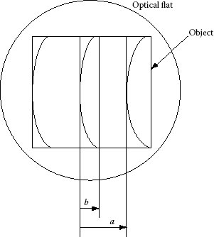
FIGURE 4.15 Flatness measurement.
Meanwhile, ratio of b/a is used as it is. For example, if this is 1/2, it is referred to as 1/2 fringe from the number of fringes or as flatness of λ/4 while wavelength λ is referenced.
If the fringe is concave to the contact side, measurement target surface is judged to be a convex surface, and if in convex shape, judged to be a concave surface. For observation of interference fringes, use of a short-wavelength spectral lamp provides good contrast; white lamp illumination is normally used and in this case, stripes are colored and judgment is made by their red color. If the wavelength λ is 0.64 μm, measurement is possible with 0.32 μm unit. Since reflectance of metals is higher than that of glasses, if increasing reflection coating is provided to a flat measurement surface, the contrast of fringes is enhanced and it becomes easy to see. It is preferable that, at measurement, the measurement object surface and optical flat are cleaned and the temperature is maintained constant for a while before measurement is commenced.
According to JIS (Japanese Industrial Standards) B7430 (1977) “Optical flat,” single surface measurement plane and both surface measurement plane are specified excluding those used as components for the interferometer and other optical measurement instrument, and the outside diameter is specified to be 45, 60, 80, 100, and 130 mm. Performances are classified into three categories. For example, allowable value of Class 1 flatness is 0.05 μm. (Class 0 is specified as reference class and performances are half of it.) If this is expressed based on wavelength λ 0.64 μm, λ/12 is obtained.
An optical parallel is an optical element in disk shape with a parallel and flat measurement surface, made of optical glass or silica glass and is used for measurements of flatness and parallelism of the measurement surface of the micrometer using light wave interference and of periodical error of its spindle. Screw pitch of the micrometer is 0.5 mm; one set of four sheets, each with thicknesses different by 0.12, 0.25, and 0.37 mm with regard to the reference, is used; thickness is provided to allow measurements every 1/4 turning. For flatness of the measurement surface of an anvil or a spindle, the optical parallel (Figure 4.16) is placed on it to generate interference fringes, and the number of fringes is counted. For parallelism, the optical parallel is sandwiched by the anvil and spindle, the measurement surface of the anvil is observed from the spindle side and the measurement surface of the spindle is observed from the anvil side, and the number of fringes is counted. For observation of the interference fringes, white lamp illumination is normally used and judgment is made by red color fringes, as mentioned in the optical flat section. Since the interval of fringes is 1/2 of wavelength λ, then wavelength λ = 0.64 μm, and flatness and parallelism can be obtained every 0.32 μm unit.
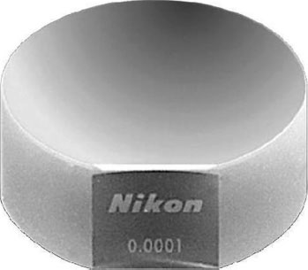
FIGURE 4.16 Optical parallel. (Courtesy of Nikon, Tochigi, Japan.)
According to JIS B7431 (1977) “Optical parallel,” outside diameter is ϕ 30 mm, thickness is 12 and 24 mm, performances are classified into two categories, and, for example, allowable value of Class 1 is flatness 0.10 μm and parallelism 0.2 μm. (Class 0 is specified as reference class and precision of flatness and parallelism is half of those, respectively.)
* Some parts of this chapter are reproduced from the chapter “Optomechanical Elements and Devices” in the Japanese book Practical Optical Keywords Book, 1999. With permission from Asakura Publishing Co., Ltd.
* Standard: One that is used as the reference of the measurement and represents a magnitude of a volume expressed by a certain unit.
† Reference instrument: One that is used as the reference of weighing in official verification or inspection at the manufacturer.