
Noncontact Dimensional and Profile Metrology by Video Measurement |
|
CONTENTS
32.1 Introduction: Background of Expansion of Metrology Applications by Video Measuring Machine
32.2 Features of Video Measuring Machines
32.3 Basic Structure of Video Measuring Machines
32.3.2 Coordinate System in Video Measurement
32.4 Optics of Video Measuring Machines
32.4.1 Performance of Optical Systems
32.4.2 Variable Magnification Optics
32.4.3.1 Diascopic (Back Light/Contour) Illuminator
32.4.3.2 Coaxial Episcopic (Top Light/Incident) Illumination
32.6 Profile Measurement Method
32.7 Height Measurement and Auto-Focus Technologies
32.7.3 Laser Auto-Focus Sensor
32.8 Conclusion: Standardization of Optical Measurement Sensors
32.1 INTRODUCTION: BACKGROUND OF EXPANSION OF METROLOGY APPLICATIONS BY VIDEO MEASURING MACHINE
Instruments that capture optically magnified images and measure objects with image processing technology are called video measuring machines, vision metrology instruments, noncontact optical metrology system, etc. The popularity of these machines along with their applications has been expanded into the industrial metrology market in the past 20 years. These video measuring machines are used to reduce human errors in measurements, metrology automation, and as a replacement for conventional optical measuring machines such as profile projectors and measuring microscopes. With these conventional measuring machines, human eyes are mainly used for recognition of measuring points with manual stage motion by handles. Video measuring machines, equipped with optics, camera, and image processor, provide automated noncontact measurement of parts. Figure 32.1 shows auto-edge detection of object measuring point from an optically magnified video image under proper illumination condition.
In addition to the automatic edge detection technology, the three axes (sometimes equipped with additional tilt and rotation axes) drive structure is one of the most important design factors of the video measuring machines for faster and microstructure object measurement abilities. Video measuring machines have improved measurement repeatability and reproducibility (gauge repeatability and reproducibility, known as GR&R*) and measurement inspection time resulting in improved productivity both for production and quality assurance departments. As to the GR&R validation method, it usually requires 3 measurement trials of each 10 parts representing actual production process by 3 appraisers. Figure 32.2 shows reduction of validation process time and improvement of GR&R by utilizing automated video measuring machines as compared with conventional manual measurement techniques. In an example of hole true position and diameter measurement including datum setting, video measurement machines greatly reduce %GRR and measurement time compared with manual measurement.
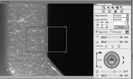
FIGURE 32.1 Edge detection of measuring point by image processing technology.
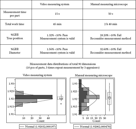
FIGURE 32.2 An example of GRR validation sheet and comparison between manual and automated measurement.
Automation of measurements requires part programming and program optimization. Therefore, as long as whole inspection time of a small-sized lot is concerned, there will not be much difference between manual and automated measurements. However, in the case of long-term process monitoring of dimensional measurements by part sampling from production of injection molding, press, electronic devices, and medical devices, automation of metrology provides advantages and merits for process improvement. Figure 32.3 shows that automated measurement of injection molded parts realized reduction of part inspection time by 80% or higher, as compared with manual measurement.
As shown in Figure 32.4, there are many applications for video measuring machines such as electronic devices, medical devices, smartphone parts, injection molding parts, pressed parts, die and molds, flat panel displays, and so on.
In the following sections, we will explain features of video measuring machines (Section 32.2), followed by basic structure of typical video measuring machines (Section 32.3), optics required for video measuring machines (Section 32.4), image processing technology (Section 32.5), profile form measurement (Section 32.6), and noncontact height sensing technologies (Section 32.7).
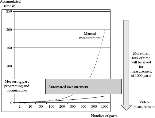
FIGURE 32.3 Inspection time comparison between manual and automated measurement.
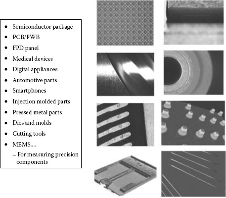
FIGURE 32.4 Application examples of video measuring machines.
TABLE 32.1
Comparison between Tactile Probe and Vision Probe
Tactile Sensor (Touch Probe) |
Noncontact Sensor(Vision Probe) |
|
Data |
A series of points (after probing correction) |
2D Data from captured image by camera |
Probing accuracy |
Touch probing mechanism accuracy (mechanical, strain gauge, etc.) |
Accuracy derived from optics, magnification and image processing |
Operation |
Touch probe tip on object surface |
Bring measurement object inside field of view |
Applications |
Large size, 3D features |
Microstructure, fragile features |
Cautions |
Deformation of parts by tactile force, optimum probing sensor length and direction |
Critical focusing on objects, removal of burrs and dusts, optimum edge detection conditions |
32.2 FEATURES OF VIDEO MEASURING MACHINES
As mentioned earlier, optical measurement machines are capable of noncontact measurement of optically magnified images of objects and high-speed and precise measurements with image processing technology. Main features of video measuring machines are as follows:
1. Magnification: High resolution (able to measure minimum 1 μm size line width)
2. Noncontact: No deformation or scratches on inspection objects
3. Image processor: Human error free, high-precision and high-speed measurements, reduction of human fatigue
Video measuring machines are often compared with tactile measurement machines. In order to characterize the features of vision probe, Table 32.1 summarizes differences between vision and tactile probes.
32.3 BASIC STRUCTURE OF VIDEO MEASURING MACHINES
Most video measuring machines consist of two major parts: one is main body with XYZ drive and linear scales, and the other is video head including magnification optics and camera. In order to expand measurement ability, some video heads incorporate built-in height detection sensors and/or tactile probes. Figure 32.5 shows an optical component layout inside a video head.
The illumination system of a video measuring machine consists of diascopic (contour or back light) illumination, coaxial episcopic (incident or top light) illumination as well as oblique ring light illumination. Images of objects being measured are optically magnified by objective lens components and projected on a camera sensor, followed by image processing of captured images. Most basic image processing technology is automated edge detection. As the video edge detection data is based on camera coordinate system, it is necessary to translate it into stage coordinate system by adding it to linear scale reading, so that a measurement result is obtained. Also, with combination of measurement point inputs, measurement application program is capable of feature calculation and construction such as line, circle (hole), distance, angle, etc. Also, a typical measurement application program has the functionality to measure two-dimensional (2D) forms by a series of edge points detected from object profiles. Because of these features of the video measuring machines, they are usually operated by a dedicated measurement application program installed on a host PC with Joystick and mouse controls (Figure 32.6).
As shown in Figure 32.7, the dedicated application software will provide full control of the main measurement hardware, consisting of a video monitor window, illumination and magnification controls, measurement tools, list, and graphic window showing programming history, etc.
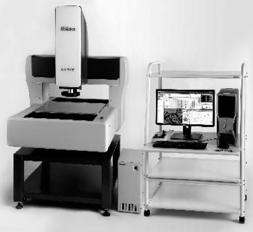
FIGURE 32.5 Optical component layout in a video measuring machine.
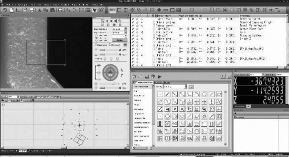
FIGURE 32.6 Nikon Computer Numerical Control video measuring system VMZ-R4540.
32.3.2 COORDINATE SYSTEM IN VIDEO MEASUREMENT
As explained in Section 32.3.1, because the video measuring machines have XYZ mechanical coordinate system from linear encoder scales and XY video coordinate system based on camera sensor, dimensional measurement data requires proper composition of these two coordinate systems. In order to ensure precise measurement ability from linear encoder scale, the hardware design of main body needs to minimize six degrees of freedom (DOF) errors—pitch, yaw, and roll errors—in XYZ drive as well as non-abbe position errors caused by scale position and measurement position, as shown in Figure 32.8a and b.
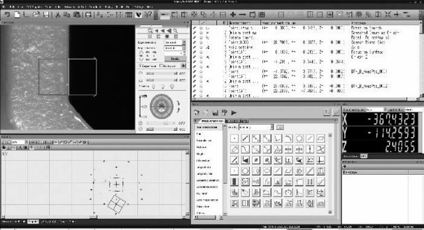
FIGURE 32.7 Main window of metrology application program.
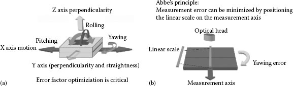
FIGURE 32.8 Hardware design requirements (a) 6DOF of motion control and (b) linear scale layout.
Furthermore, in order to combine measurement of main body and video coordinate systems, it is necessary to compensate and correct position of both coordinate systems as well as camera rotation angle (Figure 32.9). The position is given by adding detection points on a video coordinate system to the main body coordinate system. The camera rotation is a camera tilt angle correction against XY mechanical coordinate. Thus, an XY coordinate measurement result is given by the following formula (32.1):
where
xm, ym are the X and Y main body coordinate value at optical axis center
xc, yc are the X and Y video coordinate value
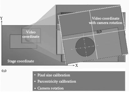
FIGURE 32.9 Camera calibration.
In addition to XY coordinate measurement, when video measuring machines have height measurement sensors such as vision auto-focus (AF), laser AF, confocal optical system, and so on, Z measurement values are calculated from main body Z axis scale reading and height displacement value from height sensors (32.2).
32.4 OPTICS OF VIDEO MEASURING MACHINES
32.4.1 PERFORMANCE OF OPTICAL SYSTEMS
One of the most important design factors of video measuring machines is their optical system performance. It is desired to have optical systems with minimized optical aberrations. Any optical system requires optimized design minimizing the five Seidel aberrations concerning monochromatic light aberrations—spherical aberration, coma, astigmatism, curvature of field, and distortion. In case of color imaging systems, chromatic aberrations must be considered as well. In particular, video measuring machines must meet requirements of “distortion-free optics” and “telecentric optics” to provide high-precision optical measurement performance.
When the optics of a video measuring machine has distortion factors, an ideal square shape might be observed as pincushion or barrel shape at the image plane. The distortion is a monochromatic aberration related to object dimensional size and proportional to the third power of image height (image length from the optical axis), while other four aberrations are related to optical image sharpness. The image distortion causes significant errors of image shape measurement inside a field of view. Therefore, it is desirable that the optical system of measurement machines minimizes distortion to ±0.1% or less (Figure 32.10).
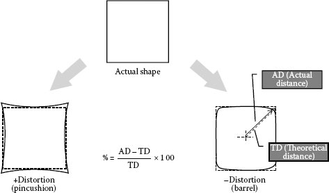
FIGURE 32.10 Distortion.
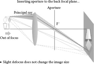
FIGURE 32.11 Telecentric optics.
Under normal optics, even at slightly defocused position, the object image size may vary and cause dimensional size error. In order to cope with this kind of error, by inserting an aperture at the back focal plane, the telecentric optics makes main rays from an object parallel to the optical axis, resulting in the image size consistency at slightly defocused position (Figure 32.11).
32.4.2 VARIABLE MAGNIFICATION OPTICS
Because the design conditions of video measuring machines must meet measurement requirements both for high and low magnification, these instruments typically include variable magnification optics such as zoom optical system and/or objective lens changer. Most video measuring machines have programmable variable magnification controls for automated measurement. In this case, as the object size varies at different magnifications, the video measuring machines perform magnification compensation (pixel size correction) for accurate dimensional measurement. By combination of these technologies, the video measuring machine provides wider field of view at lower magnification and guaranteed measurement accuracy at higher magnification. Figure 32.12 is an example of magnification position images covering 120× zoom range (Nikon Z120X optical head).
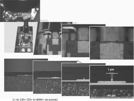
FIGURE 32.12 Nikon Z120X optical head image.
The variable magnification systems in the video measuring machines have mechanisms to minimize measurement errors caused by magnification changes. At least, the following two compensation factors are needed: one is magnification compensation (pixel size calibration), and the other one is optical axis center compensation (parcentricity calibration).
1. Magnification compensation: Magnification (or pixel size) is corrected by measuring patterns of which size are already known and traceable to national standards. The calibration patterns are dedicated to each measurement machine.
2. Optical axis center (parcentricity) compensation: The eccentricity of optical axis center at each magnification position adds to positional error factor. In order to compensate it, the video measuring machines measure XY coordinate position of a circle pattern at different magnifications and obtain coordinate differences as correction values.
In addition to these, when the video measuring machine provides high-precision height measurement ability, focal position reproducibility at different magnification positions—parfocality compensation—must also be considered.
Video measuring machines usually have three illumination systems: a diascopic (back light/contour) illuminator, a coaxial-episcopic (top light/incident) illuminator, and oblique light illuminators, which can visualize edge of small height gaps. In recent years, instead of halogen light source, white LED illuminators are incorporated in video measuring machines, due to their high performance, low energy consumption, and light intensity.
32.4.3.1 Diascopic (Back Light/Contour) Illuminator
The dimensions and forms of parts such as pressed parts, gears, semiconductor leadframes, die, and mold parts are measured by back light illumination. In order to measure these parts precisely, it is critical to have even illumination on measurement plane (Figure 32.13).
High-intensity LED light source is now widely used for diascopic illumination providing lower power consumption, longer life, stability, and faster light control response, as compared with halogen light source. Also, new illumination optics has been developed for LED light sources using fly-eye lenses, which provides even illumination and higher lighting efficiency (Figure 32.14).
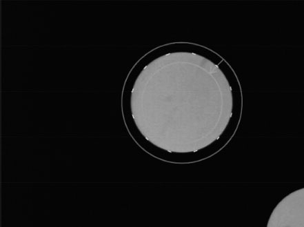
FIGURE 32.13 An image by diascopic (back light/contour) illumination.
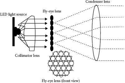
FIGURE 32.14 Light source optics using fly-eye lens.
32.4.3.2 Coaxial Episcopic (Top Light/Incident) Illumination
The episcopic illumination is used for illuminating part surfaces such as metal surface, integrated circuit patterns, etc. While the structure of episcopic illumination system is similar to that of diascopic illumination, the episcopic illumination may have a built-in 1/4λ plate on the top of objective lens to prevent unnecessary light reflection or glare from mirror surfaces (Figure 32.15).
When edge recognition is difficult with episcopic lighting, oblique LED light illumination with independent segment lighting control system is used for better edge recognition (Figure 32.16). Some video measuring machines have also lighting angle control to produce optimum illumination angle for visualization of edges (Figure 32.17). Although the oblique illumination will produce high contrast edges, it is necessary to pay attention to the fact that it may sometimes shift the measuring points because of shadows on chamfered edges.

FIGURE 32.15 Episcopic lighting image.
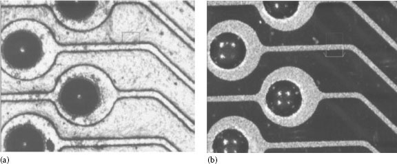
FIGURE 32.16 Effects of oblique illumination. (a) Episcopic illuminator and (b) oblique ring LED illuminator.
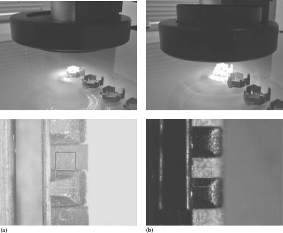
FIGURE 32.17 (a) Normal lighting angle and (b) oblique light angle is set to middle position.
Image processing technologies have been widely adopted for industrial inspection and measurement applications with the evolution of semiconductor devices since the late 1980s. In the early stage, the image processor units were external hardware processor units and/or frame grabbers for workstations/PCs. Nowadays, thanks to improvement of CPU performance including digital signal processor, camera data transfer protocols, and so on, it is possible to handle the image processing on the application programs running on personal computers. The image processing technologies of the video measuring machines can be classified into the following categories:
1. Edge point detection: input measuring points
2. Image rectification: enhancement of edges for easier and stable detection
3. Pattern matching: part alignment, measurement target search
4. Vision AF: AF by image processing
These technologies are discussed in detail in the following sections.
Figure 32.18 shows examples of edge point detections. Figure 32.18a shows averaged edge point detection. As seen in Figure 32.18a, the technique of averaged edge detection can be used for dust/burr removals. Figure 32.18b shows multipoint edge detection on a circle feature.
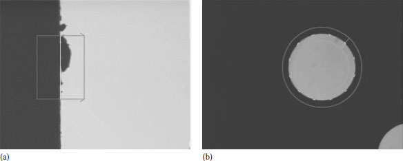
FIGURE 32.18 Video edge detection. (a) Average edge detection. Dust/burr removals by edge averaging. (b) Multipoint edge detection (circle feature).
General image processing technologies use grayscale processing to find edges with the resolution below camera pixel size. Grayscale processing converts the image on each pixel of video sensor into gray values from white to black (e.g., 256) levels. With an appropriate interpolation of gray levels between pixels after filtering, it is possible to detect edges with a resolution of 1/10 or smaller of pixel size. Because the edges are detected by the rate of change of brightness, instead of absolute brightness level difference, the measurement will be highly repeatable and reproducible regardless of illumination and/or part deviations in each part measurement. Figure 32.19 shows a simplified model of edge detection mechanism. In order to detect a peak point as an edge, the A/D (Analog to Digital), converted data on every pixel is accumulated in one direction (projection), followed by edge filtering (derivative) and interpolation such as spline curve fitting, which is called “subpixel processing.” In the case of reasonably high magnification (small pixel size), submicrometer repeatability can be achieved.
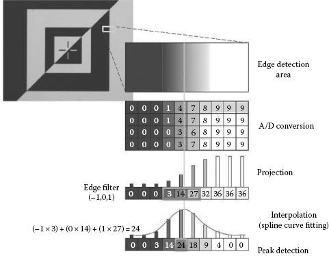
FIGURE 32.19 Principle of edge detection (simplified model into 10 gray levels).
When edge points are still ambiguous even after magnification adjustment and lighting optimization, image filters can be used to improve edge detection. For measurement purposes, it is not advisable to apply image filters such as erode or dilate, which may change edge positions. Figure 32.20 shows an example of edge enhancement by FFT (Fast Fourier Transform) filter to extract an edge. The signal peak level becomes higher after applying the edge enhancement filter.
When video measuring machines are used to find automatically measurement targets and/or to find the part orientation skewed in XY plane, precise object search functions are required. The search functions by pattern matching technologies are indispensable in metrology automation (Figure 32.21).
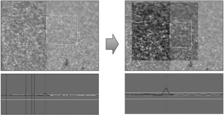
FIGURE 32.20 Image rectification by FFT filter.
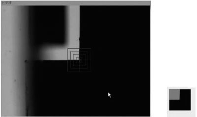
FIGURE 32.21 Recorded image (right) and pattern matching (left) in a field of view.
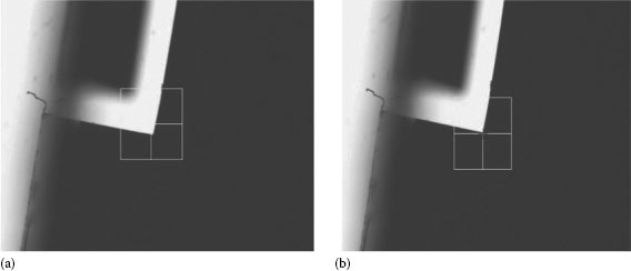
FIGURE 32.22 Geometrical feature pattern matching: normalized crossed-correlation method fails in search (a), while geometrical feature pattern matching searches skewed patterns (b).
Pattern matching can be achieved by finding the image position, which is higher correlation coefficient (closer to 1) after normalized cross-correlation to avoid effects of brightness level difference between actual target image and recorded image. The normalized cross-correlation formula of pattern matching can be explained as in the following (32.3):
where
f is the brightness of each pixel of a target image
g is the brightness of each pixel of a recorded image
are the averaged brightness levels of the search area
n is the number of pixels
After normalized cross-correlation search is performed, its results are X and Y coordinate value of matched location. Search score (correlation coefficient) is also obtained. While this pattern matching technique is widely used for industrial metrology fields, it may fail in appropriate matching with recorded image, if the target image has a large skewed or rotated angle and/or its size is scaled. In order to find objects under such conditions, new pattern matching algorithms using geometrical feature characterization have been developed and implemented for vision metrology (Figure 32.22).
In automated optical measurements, it is critical to have precise AF functions to correct for images that are not in proper focus due to variations in part thickness and/or part warpage. Video measuring machines incorporate video AF function to find a focus position from image contrast at different heights. Video AF function can be performed at edge positions and at part surfaces. The principle of vision AF is (1) capture images at a constant sampling step in Z axis direction, (2) find contrast values in an area of interest, and (3) estimate the contrast peak point with an interpolation calculation such as Gaussian fitting from maximum contrast point and its neighborhood data points (two points or more). Fitting formula can be expressed as follows (32.4) (Figure 32.23):
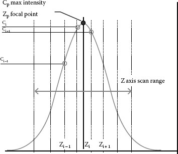
FIGURE 32.23 Height detection by vision AF.
where
Cp is the estimated value of contrast peak
Zp is the Z axis value in Cp (focused position)
Ci, Ci + 1, Ci − 1 are the maximum contrast value and its neighborhood data points
Zi, Zi + 1, Z are the Z axis values in Ci, Ci + 1, Ci − 1, respectively
Some video measuring machines incorporate pattern (Ronchi grid) projection mechanism to add contrast on mirror and/or transparent surfaces. The accuracy of video AF is dependent on the depth of focus defined by a value expressing optical performance, called numerical aperture (NA). Therefore, it is advisable to use high NA optics to meet requirements of height measurement. The video AF normally produces repeatability and reproducibility below the depth of focus with interpolation processing. The depth of focus can be expressed by the following formula (32.5) and can be used as a guide value for vision AF accuracy. For instance, in the case of NA = 0.5 and 500 nm wavelength for observation, the depth of focus will be 1 μm.
where λ is the wavelength used for observation.
More advanced video AF function supports simultaneous height detections in a field of view by placing multiple detection areas for height measurement purposes. The functionality is suitable for continuous height difference measurements in a single Z axis scan. Figure 32.24 shows the example of maximum height detection of a wire bonding loop in a semiconductor device.
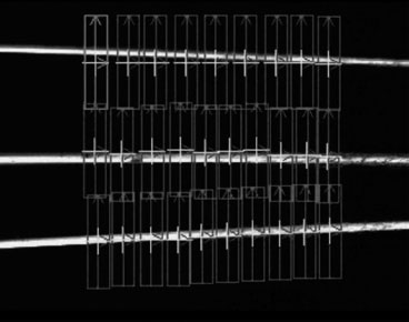
FIGURE 32.24 Loop height measurement by multiple-vision AF.
32.6 PROFILE MEASUREMENT METHOD
In order to measure curved shapes such as spur gear teeth shape defined by involute spline curve or cam profiles consisting of many different arcs, the video measuring machines measure these curve features by a series of points with the constant point-spacing, followed by comparison with nominal shape from CAD (Computer Aided Design) data making it possible to calculate the error between actual measured shape and the ideal shape. This type of measurement is typically known as profile (contour) measurement. There are two methods used in the measurement process with constant point-spacing: (1) Auto-edge tracing along profile shapes: this is a method used to find edge points at constant point spacing. The next edge point can be estimated from the points, which have been already measured. (2) Measurement points generated from CAD data: edge detection tools can be automatically generated from feature data in CAD (Figure 32.25).
After the profile measurement, the application program calculates errors between the actual part profile data and the CAD nominal profile data. When the profile of line tolerance [2] in a drawing allows for parallel shift and/or rotation to minimize the part-to-CAD errors, the application program will perform the best-fit correction. Figure 32.26 shows an example of gear teeth profile measurement report. The report is helpful in knowing errors graphically with tolerance areas defined by CAD data.*
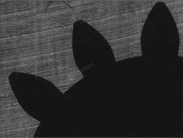
FIGURE 32.25 Gear teeth profile measurement.
For details, refer to ASME Y14.5–2009.
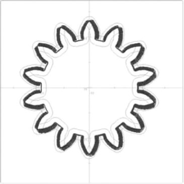
FIGURE 32.26 Gear teeth profile evaluation.
32.7 HEIGHT MEASUREMENT AND AUTO-FOCUS TECHNOLOGIES
In this chapter, we will explain a couple of examples of noncontact height measurement technologies: shape from focus (SFF) probe, confocal sensor, and laser AF sensor. The SFF sensor can be regarded as an expansion of vision AF technologies. The confocal sensor is used for precise height measurements of features in a wide field of view. The laser AF sensor can be used as an accurate and easy height measurement tool, regardless of optical magnification.
As explained in Section 32.5.4, video measuring machines have the video AF function, which focuses on the part surfaces by image contrast. Based on the video AF focusing algorithm, some video measuring machines have an area height measurement sensor to capture the height information in each pixel on the image sensor. This measurement sensor is called SFF sensor. By adding the video image to the area height information from SFF sensor, the video measuring machines can also produce an extended depth of focus (EDF) image (Figure 32.27).
Similar to the video AF, the SFF sensor is a passive sensor, which is dependent on the image contrast derived from the surface texture (roughness) of a part. Therefore, it is not suitable for a surface without texture such as mirrors, highly polished surfaces, etc. In order to measure surfaces without texture by the SFF sensor, some video measuring machines use a built-in pattern projector inside the optics. By projecting the patterns actively on the part surfaces, the SFF sensor measures the height information at the peak contrast of the patterns on each pixel (Figure 32.28).
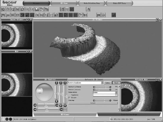
FIGURE 32.27 An example of EDF image captured by SFF method.
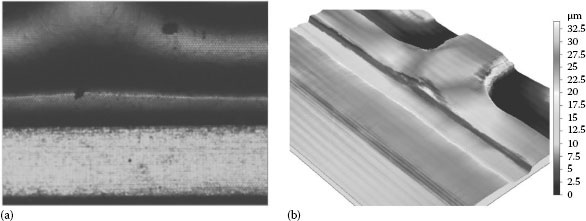
FIGURE 32.28 Pattern projection on surface (a) and resulting 3D height image by SFF sensor (b) of Nikon multisensor metrology system, HN-6060.
As in the case of the video AF, the accuracy of SFF sensor depends on the NA of the optics. In general, with the increase of NA, the field of view becomes smaller, resulting in longer measurement time. Therefore, it is necessary to optimize the measurement accuracy and speed by adjusting magnification and image contrast.
In order to meet the precise measurement requirements for small height and surface texture, some video measuring machines feature a precise height measurement sensor, which is known as confocal optics, as shown in Figure 32.29a. Confocal optics with many pinholes on a built-in Nipkow spinning disk is designed to guide image rays only at the focal position. Therefore, the resulting image has a very narrow depth of field as compared with a normal optical image. By this optically sliced image from the confocal optics, the video measuring machine is able to measure height information within the FOV (field of view) from continuously captured images with Z axis scan at constant steps and dedicated image processing. Similar to the SFF sensor, the image processor detects Z axis height on each pixel on a camera sensor as shown in Figure 32.29b. Interpolation is then used to calculate its maximum contrast point from sampled confocal images by Z axis scanning at constant steps.
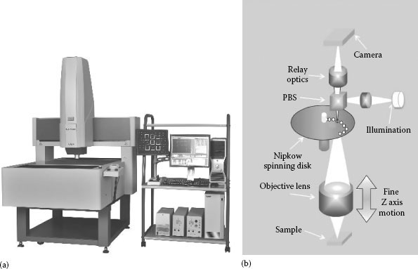
FIGURE 32.29 (a) Nikon Confocal Nexiv VMZ-K3040. (b) Confocal optics with Nipkow spinning disk.
With this measurement method, it is possible to measure height dimensions and form as well as 2D object locations and dimensions in a field of view. In metrology applications, video measuring machines equipped with a confocal head are used for the measurement of high density bump location and height of semiconductor devices (Figure 32.30) and surface texture (roughness) evaluation by surface analysis software (Figure 32.31).* A and B, and monitors the signal difference level between the sensors (signal S = A − B) during the focus motion. The focus position is adjusted at the zero-cross position of signal S. When the NA of objective lens used for the TTL laser AF is 0.35, the height measurement repeatability of standard sample will be 0.5 μm (2σ) or lower.
32.7.3 LASER AUTO-FOCUS SENSOR
For a displacement measurement method to measure part thickness, flatness, etc., some video measurement machines use an active AF sensor using a laser light source. In many cases, the laser AF sensor is used with 2D video measurement. Therefore, it is advisable to adopt the through-the-lens (TTL) design, enabling to guide and detect the laser beam through the optics such that the focusing operation can be done in the same field of view as the video measurement. Figure 32.32a explains the structure and principle of the “knife edge” methodology for TTL laser AF. The detector uses a two-segment sensor,*
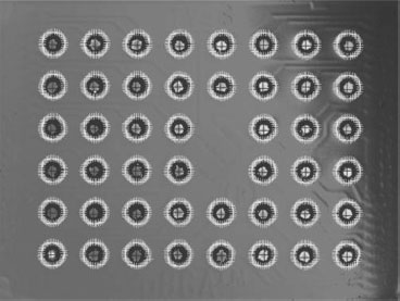
FIGURE 32.30 Simultaneous bump height and location measurement in an FOV by the confocal method.
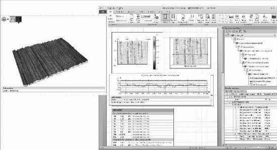
FIGURE 32.31 Three-dimensional view and roughness evaluation of the confocal image by surface analysis software.
In addition to the single point height measurement, the video measuring machine with the TTL laser AF provides scanning measurement ability to measure part surfaces continuously. The scanning measurement can be achieved by XY stage motion and Z axis continuous focusing motion with real-time feedback and compensation of S signal level. Figure 32.33 is an example of measurement of surface texture of a camera grip. It is possible to observe the structure of surface texture and depth/height after removing form by the surface analysis software.
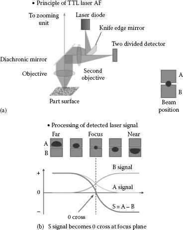
FIGURE 32.32 (a) Knife edge style active laser auto-focus and (b) laser signal processing.
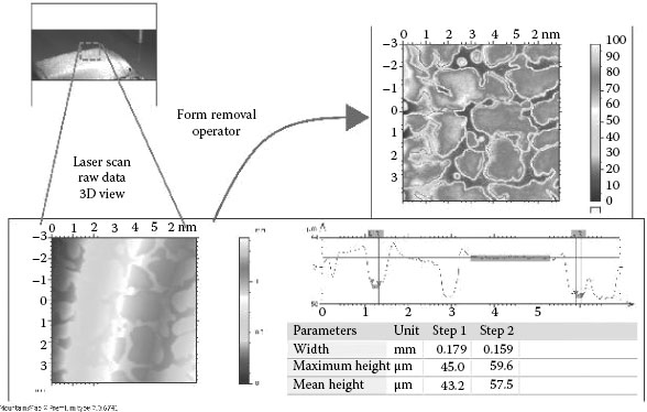
FIGURE 32.33 Measuring result of surface texture of a camera grip. After form removal of camera grip, it is possible to evaluate the surface texturing.
32.8 CONCLUSION: STANDARDIZATION OF OPTICAL MEASUREMENT SENSORS
We have introduced the up-to-date technologies of the video measuring machines in this chapter and explained expansion of their measurement applications. The evolution and development of the video measuring machines will continue with optical measurement technologies and solution proposals from different manufactures. Today, the popularity and practical applications of video sensors require their classifications and standardization, resulting in the ISO 10360-7:2011 geometrical product specifications (GPSs)—Acceptance and reverification tests for coordinate measuring machines (CMM)—Part 7: CMMs equipped with imaging probing systems [3]. In this ISO standard, the video measurement probe is positioned as per the CMM standard. In addition to this standard, as explained in Section 32.7, some video measuring machines, having noncontact precise height measurement sensors, might exceed the standard category of the video measuring machines. These noncontact height measurement sensors will be classified and standardized in the ISO25178-6 Surface Texture—Area—Part 6: Classification of methods for measuring surface texture [4].
We thank Mr. Kambiz “Tom” Banafshe, business development manager, Nikon Metrology, Inc., for his assistance and suggestions to write this chapter.
1. AIAG (Automotive Industry Action Group) Copyright 2010 Chrysler Group LLC, Ford Motor (2002).
2. ASME (American Society of Mechanical Engineers) Y14.5–2009 Dimensioning and Tolerancing.
3. ISO 10360-7:2011 Geometrical product specifications (GPS)—Acceptance and reverification tests for coordinate measuring machines (CMM)—Part 7: CMMs equipped with imaging probing systems.
4. ISO 25178-2:2012 Geometrical product specifications (GPS)—Surface texture: Areal—Part 2: Terms, definitions and surface texture parameters.
* GR&R is one of the measurement system validation methods. In accordance with proper analytical procedure, GR&R shows repeatability and reproducibility of gauging dimensions of parts. The former is derived from precision of measurement system and the latter from skill and knowledge level of equipment operators. GR&R is usually validated by an index, which divides variation of repeatability and reproducibility (5.15 × sigma) by either process variation or tolerance range. When the index called %GRR is less than 10%, the analyzed measurement system variation is sufficiently smaller than process variation and is considered valid. For details of GR&R, refer to Measurement Systems Analysis, Reference Manual, Third Edition, AIAG: ISO/TS16949, 2002 [1].
* MountainsMap X software based on Digital Surf’s Mountains Technology was used for surface analysis in this chapter.
* Today, Nikon proposes a new TTL laser AF structure with additional sensor segments of the detector to avoid effects from reflection of back-side surface of a transparent part.