
1
Blinking an LED
In this first project, you’ll connect an LED to your Pi and make it blink with a python script. Learning how to blink an LED using the GPIO pins is an important step in your Pi education; once you know how to control an LED, you can control practically any output, whether it’s a motor, a lamp, or even a toaster.

PARTS REQUIRED
Raspberry Pi
Breadboard
5 mm LED
330 Ω resistor
Jumper wires
INTRODUCING THE GPIO PINS
The General Purpose Input/Output (GPIO) pins allow you to connect electronic hardware, like LEDs and sensors, to your Pi. They can be used to both read and send information, allowing your Pi to interact with the real world.
The Raspberry Pi 3 Model B board has a double row of 40 GPIO pins, shown in Figure 1-1. This layout is the same for the Pi 2 Model B and Pi 1 Model B+, but slightly different from the Pi 1 Model A and B, which have only the first 26 pins. Check the “Raspberry Pi GPIO Pin Guide” on page 261 if you’re using a board other than the Raspberry Pi 3 Model B.
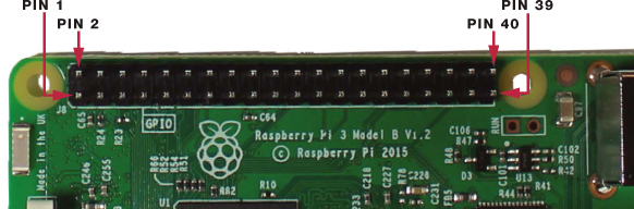
FIGURE 1-1: Raspberry Pi GPIO layout
There are two ways to refer to a GPIO pin: its name (which is known as GPIO numbering or Broadcom numbering) or by its corresponding pin number (which is known as physical numbering). For example, GPIO 25 corresponds to pin 22. Throughout this book, we'll refer to GPIO pins by their names. GPIO pins can be set to HIGH, which outputs 3.3 V and turns a component on, or LOW, which outputs 0 V and turns the component off.
FUNCTION |
NAME |
NUMBER |
NUMBER |
NAME |
FUNCTION |
DC power |
3.3 V |
1 |
2 |
5 V |
DC power |
SDA1, I2C |
GPIO 2 |
3 |
4 |
5 V |
DC power |
SCL1, I2C |
GPIO 3 |
5 |
6 |
GND |
|
GPIO_GCLK |
GPIO 4 |
7 |
8 |
GPIO 14 |
TXD0 |
|
GND |
9 |
10 |
GPIO 15 |
RXD0 |
GPIO_GEN0 |
GPIO 17 |
11 |
12 |
GPIO 18 |
GPIO_GEN1 |
GPIO_GEN2 |
GPIO 27 |
13 |
14 |
GND |
|
GPIO_GEN3 |
GPIO 22 |
15 |
16 |
GPIO 23 |
GPIO_GEN4 |
FUNCTION |
NAME |
NUMBER |
NUMBER |
NAME |
FUNCTION |
DC power |
3.3 V |
17 |
18 |
GPIO 24 |
GPIO_GEN5 |
SPI_MOSI |
GPIO 10 |
19 |
20 |
GND |
|
SPI_MISO |
GPIO 9 |
21 |
22 |
GPIO 25 |
GPIO_GEN6 |
SPI_CLK |
GPIO 11 |
23 |
24 |
GPIO 8 |
SPI_CE0_N |
|
GND |
25 |
26 |
GPIO 7 |
SPI_CE1_N |
I2C ID EEPROM |
DNC |
27 |
28 |
DNC |
I2C ID EEPROM |
|
GPIO 5 |
29 |
30 |
GND |
|
|
GPIO 6 |
31 |
32 |
GPIO 12 |
|
|
GPIO 13 |
33 |
34 |
GND |
|
|
GPIO 19 |
35 |
36 |
GPIO 16 |
|
|
GPIO 26 |
37 |
38 |
GPIO 20 |
|
|
GND |
39 |
40 |
GPIO 21 |
|
WARNING
The GPIO pins are designed to work at 3.3 V, so if you connect them to higher voltages, you’ll permanently damage your Raspberry Pi.
The pins highlighted in gray, pins 27 and 28, are DNC, or “do not connect,” pins. The Raspberry Pi also has eight GND (ground) pins—highlighted in black in the table—for connecting ground to your circuits. There are four power pins, two 5 V pins and two 3.3 V—highlighted in red and orange, respectively—to supply power. Several pins have special features; for example, the pins highlighted in yellow are used in serial peripheral interface (SPI) communication, and the ones highlighted in green are used for inter-integrated circuit (I2C) communication. You’ll learn about these communication protocols in Project 3 and Project 7, respectively.
INTRODUCING LEDs
LEDs come in a wide variety of sizes, shapes, and colors, and some can even mix colors to produce almost any color. In this project you’ll use a simple 5 mm red LED.
An LED, or light-emitting diode, is—as its name suggests—a diode that emits light. Diodes are electronic components that have polarity, meaning they allow current to flow in only one direction, from positive to negative. LEDs, like all diodes, have a positive connection known as an anode, and a negative connection known as a cathode. The two legs, or leads, on LEDs are different lengths to help you identify which is positive and which is negative, illustrated in Figure 1-2. The longer lead is the anode (+) and the shorter lead is the cathode (–).

FIGURE 1-2: A 5 mm red LED
FINDING THE RIGHT RESISTOR
LEDs can handle only so much current before they overload and burn out, which can potentially damage the LED and even the Pi board. To prevent this, you must always connect LEDs in series with a resistor: a small component that limits the amount of current passing through it.
Resistors come in all sorts of values, and you need one that’s strong enough to protect your component without being so strong that it limits the component’s capabilities. For example, a stronger resistor can dull the light an LED gives off. The appropriate resistance value depends on the LED you’re using—most LEDs you’ll use in electronics can handle a maximum current rating of 20 mA. For the LED in this project, picking up a resistor of any value between 220 Ω and 470 Ω is fine, and within this range, a lower resistance value will result in a slightly brighter LED.
NOTE
We recommend that you purchase a 1/4 W resistor assortment that spans a wide range of resistance values. These will meet most of your needs.
The resistance value is indicated by the color bands on the resistor. Resistors usually have four bands, as shown in Figure 1-3. The first two represent the first two digits of the value. The third is a multiplier representing the number of zeros after the first two digits. The fourth is the tolerance of the resistance, which notes the percentage that the actual resistance might be above or below the given value. For example, a 330 Ω resistor with a 5 percent tolerance might be any value between 313.5 Ω and 346.5 Ω.

FIGURE 1-3: A 330 Ω resistor
If you need help identifying a resistor, check the resistor color card in “Decoding Resistor Values” on page 264.
WIRING THE CIRCUIT
Now you’re ready to build your first circuit. All the projects in this book use a solderless breadboard, which gives you an inexpensive and easy way to build circuits without having to connect the components using solder. If you’ve never used a breadboard before, make sure to read “How Does a Breadboard Work?” on page 42 before beginning.
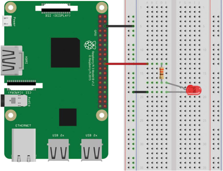
To wire an LED to the Raspberry Pi, follow these next steps. Use the wiring diagram in Figure 1-4 as a reference, and review Figure 1-1 for pin locations if you need to.
Connect a blue breadboard rail to one of the Raspberry Pi GND pins (pins 6, 9, 14, 20, 25, 30, 34, and 39 all provide GND).
Insert the LED into the breadboard.
Insert the 330 Ω resistor into the breadboard so that one side is connected to the LED anode (the longer, positive lead).
Connect the other side of the resistor to GPIO 25 (pin 22) with a jumper wire.
Connect the LED cathode (the shorter, negative lead) to the GND power rail.
LISTING 1-1: Wiring an LED to the Raspberry Pi. The LED lead with a bend in it is the anode.
We’ve given you instructions on where to place the resistor, but really it doesn’t matter whether it’s connected to the anode or cathode as long as it is connected to one. You might wonder why we didn’t just connect the LED cathode directly to pin 6 (GND), since we only need the GND rail for that one connection. The reason is that it’s good practice to use the breadboard GND rails, which will become more useful in more advanced circuits.
HOW DOES A BREADBOARD WORK?
Wiring a circuit using a breadboard is as easy as plugging and unplugging components. A breadboard has rows of holes that connect with copper strips underneath, so you just need to insert the components into those holes and then use jumper wires to connect them. The breadboard holes are connected to each other in a specific way, shown here by the orange lines.
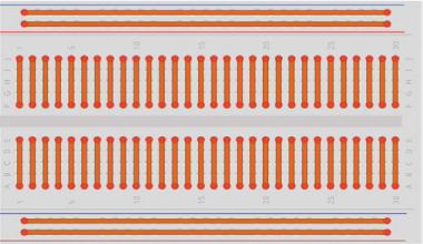
Each individual line is electrically isolated from the others. The horizontal lines are the power rails, used to connect the power supply: the blue rails are used to connect GND and the red rails to connect power. In the middle of the breadboard is a divide that splits the rows on either side. You should place your components in these rows. Components in the same row, on the same side of the center divide, will be connected by the copper strips beneath.
WRITING THE SCRIPT
To keep all your projects organized, create a folder called Projects in your desktop environment to save all your projects’ scripts. Inside the newly created folder, create a new folder called LEDs where you’ll save the LED projects in this book.
In simple terms, the blinking LED project works as follows:
The LED turns on for 1 second—GPIO 25 set to HIGH.
The LED turns off for 1 second—GPIO 25 set to LOW.
The LED is on again for 1 second—GPIO 25 set to HIGH.
The LED is off again for 1 second—GPIO 25 set to LOW.
This pattern continues until you tell the program to stop.
Throughout this book, we’ll control the Raspberry Pi GPIOs using a Python library called gpiozero. The gpiozero library provides a collection of interfaces for everyday components like LEDs, buttons, potentiometers, sensors, and much more.
Entering the Script
Open Python 3 (IDLE) and go to File ▸ New File to create a new script. Copy the following code to the Python Editor and save the script as blinking_led.py inside the LEDs folder (remember that you can download all the scripts at https://www.nostarch.com/RaspberryPiProject/):
#importing necessary libraries
➊ from gpiozero import LED
➋ from time import sleep
#create an object called led that refers to GPIO 25
➌ led = LED(25)
#create variable called delay that refers to delay time in seconds
➍ delay = 1
➎ while True:
#set led to on for the delay time
➏ led.on()
print('LED set to on')
➐ sleep(delay)
#set led to off for the delay time
➑ led.off()
print('LED set to off')
sleep(delay)
There’s quite a lot going on here, so we’ll go through each major code section one at a time.
Importing Libraries
At ➊ you import LED from the gpiozero library to control the GPIO that the LED is connected to. Then you import the sleep() function from the time module ➋.
Declaring the Pin
At ➌ you create an LED object called led that refers to GPIO 25, which is the GPIO the LED is connected to. When you create and use this LED object, Python knows GPIO 25 is an output and thus should be set to HIGH or LOW. After this declaration, you can use led to refer to your GPIO 25.
Starting the while Loop
At ➎ you start a while loop with the condition True, which means this loop will run forever until you stop the program yourself. The lines of code that follow the loop declaration are indented, telling Python that this is the content of the loop to be run as long as the while condition is met.
Setting the Digital Output
Next you need to set the digital output for the LED. You use the led.on() function ➏ to set GPIO 25 to HIGH, turning the LED on, and the led.off() function ➑ to set GPIO 25 to LOW, turning the LED off. There is a pause of 1 second between each LED state using the sleep() function ➐, which creates the blinking effect. The code stops where it is and waits for the amount of time specified in the delay variable (given in seconds) ➍ before proceeding to the next line of code. This allows you to keep the LED on or off for a given period of time.
Running the Script
To run the script, first save it and then press F5 or go to Run ▸ Run Module. Your circuit should look something like Figure 1-5, with your LED turning on and off every second. To stop the running program, press CTRL-C.
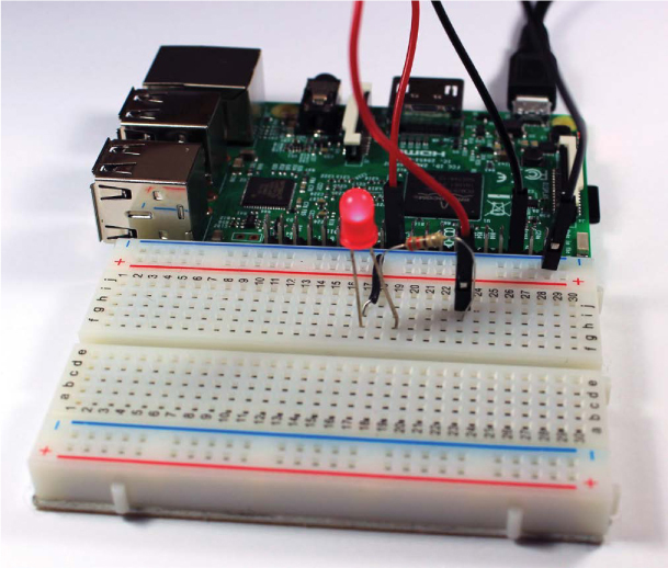
FIGURE 1-4: The completed project
Congratulations—you’ve just built your first working project!
TAKING IT FURTHER
The best way to learn electronics and programming is by experimenting. Here are two simple ideas for modifications you could try:
- Change the delay time in the script.
- Modify the circuit and script to control more than one LED.
See if you can use what you learned in this project to figure out each task.