5
Rainbow Light Strip
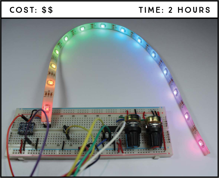
In this project you’ll create a rainbow light effect using an addressable RGB LED strip. You’ll use a pushbutton to start and stop the rainbow effect, and you’ll control the rainbow’s speed and brightness using two potentiometers.
PARTS REQUIRED
Raspberry Pi
Breadboard
WS2812B addressable RGB LED strip
Logic level conver ter module BSS 138
Two 10 kΩ potentiometers
MCP 3 008 chip
Pushbutton
Three header pins
Jumper wires
SOFTWARE REQUIRED
WS2 81X library
INTRODUCING THE WS2812B ADDRESSABLE RGB LED STRIP
For the rainbow light effect, you’ll use the WS2812B RGB LED strip, which is available in many different sizes. The strip comes in a reel, as shown in Figure 5-1, and you can cut off as long a section as you need.

FIGURE 5-1: WS2812B addressable RGB LED strip on a reel
The strip shown in Figure 5-1 is 5 meters long with 300 addressable WS2812B RGB LEDs wired in series, and later you’ll cut a section of 14 LEDs to use in this project. There are cutting marks, shown in Figure 5-2, along the entire length of the strip.

FIGURE 5-2: WS2812B addressable RGB LED strip pins
The color and brightness of each LED can be controlled individually, allowing you to produce amazing effects easily. Each LED has an integrated circuit (IC) built right in, which means you can control the whole strip using just one GPIO pin, connected to the middle pin—the Data pin—at the end of the strip (see Figure 5-2).
Prepare the LED strip for this project as follows:
Cut a strip of 14 LEDs along the cutting marks shown on the strip.
Solder header pins to the 5 V, Data, and GND pins as shown in Figure 5-2.
NOTE
We’ve found that a Raspberry Pi 5 V pin (such as pin 2 or pin 4) is capable of powering a strip of 20 LEDs or fewer, but in projects where you’re using a longer strip, you’ll need to use an external 5 V power supply to provide enough current.
Now you need to figure out your power supply. The LED strip requires a 5 V power source. You can determine the amps you need from the amount of power each LED requires. An individual LED draws up to 60 mA at full brightness (which produces white light), but since you’ll rarely need all LEDs at their maximum value for any length of time, you can safely estimate 20 mA per LED. So if your strip is 14 LEDs long, you’ll need a 5 V power source with approximately 20 × 14 = 280 mA.
The Data pin that controls the strip needs a 5 V signal, but the Pi GPIOs operate at 3.3 V. To get the 5 V you need, you’ll use a component called a logic level converter.
INTRODUCING THE LOGIC LEVEL CONVERTER
A logic level converter allows you to convert 3.3 V signals to 5 V signals. There are many types of logic level converter, but in this project you’ll use the two-channel logic level converter bidirectional module shown in Figure 5-3. (To find the same logic level converter module we’re using, search online for logic level converter module bss138.)
The bidirectionality of this module allows you to convert data in both ways—from 3.3 V to 5 V and from 5 V to 3.3 V. You won’t need to convert 5 V to 3.3 V in this project, but having this more flexible model in your toolkit (versus a unidirectional model) can come in handy for future projects. This logic level converter also has two channels, channel 1 and channel 2. In this project you’ll use only one of the channels to control the LED strip’s Data pin.

FIGURE 5-3: Two-channel logic level converter bidirectional module
More likely than not, your module will come with the header pins separate, so you’ll need to solder the pins to it to make it breadboard-friendly. Break off two rows of six header pins, and solder one pin to each tiny hole.
The module has a low-voltage side (left side of Figure 5-3), to which you attach everything that’s at 3.3 V, and a high-voltage side (right side), where you attach everything at 5 V. For this project, you need to use one of the pins highlighted in red, as you want to send 3.3 V data and convert it to 5 V.
To use the logic level converter, connect GND on both sides, 3.3 V on the low-voltage side, and 5 V on the high-voltage side. Then, connect data from the Pi on one of the TX1 pins—you can use either channel 1 or channel 2—and get the 5 V data on the corresponding TX0 pin.
WIRING THE CIRCUIT
At this point, you should have cut your strip to size (14 LEDs) and soldered header pins both to the end of the strip and to the logic level converter. Now you’re ready to wire the circuit. To do so, you’ll connect together a pushbutton, two potentiometers via the MCP3008 chip, and the addressable RGB LED strip using the logic level converter module, as shown in Figure 5-4.
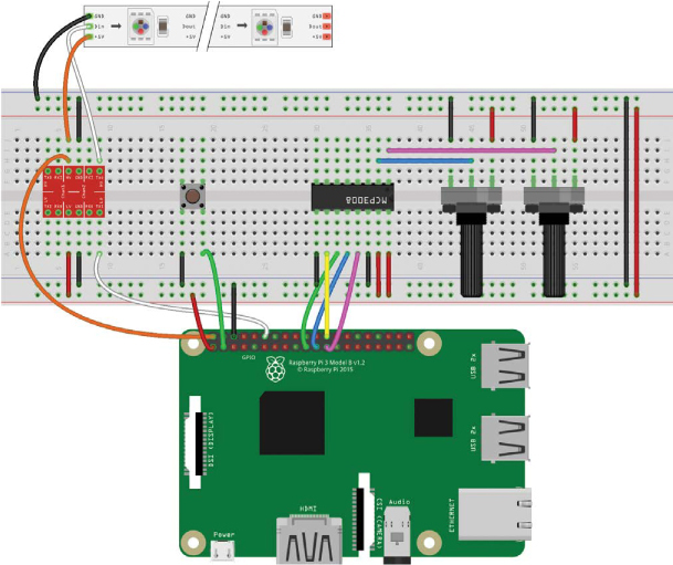
FIGURE 5-4: Circuit for controlling the RGB LED strip
WARNING
Remember that you can’t connect 5 V to the Pi GPIOs, as that can permanently damage your board.
NOTE
To identify the MCP3008 pins, orient the chip so it’s facing you with the half-circle cutout at the top. The first pin is the top left and the last pin is the top right. See “Analog-to-Digital Converters” on page 55 for a full MCP3008 pinout description.
Connect the GND and 3.3 V pins to the breadboard rails.
Insert the MCP3008 chip in the middle of the breadboard with the two sides straddling the center divide.
Insert two potentiometers in the breadboard, wiring one’s outer lead to GND and the other’s outer lead to 3.3 V.
Connect the MCP3008 chip as shown in the following table. It doesn’t matter which potentiometer you connect to which pins; they will work the same way.
MCP3008
CONNECT TO
1
One potentiometer’s middle lead
2
Other potentiometer’s middle lead
9
GND
10
GPIO 8
11
GPIO 10
12
GPIO 9
13
GPIO 11
14
GND
15
3.3 V
16
3.3 V
Insert a pushbutton into the breadboard, straddling the center divide. On one side of the center divide, connect one pin to GND and the other pin to GPIO 2.
Insert the RGB LED strip pins into the breadboard.
Insert the logic level converter into the breadboard. Connect the low-voltage side as directed.
LOGIC LEVEL CONVERTER
RASPBERRY PI
TX1 (channel 2)
GPIO 18
LV
3.3 V
GND
GND
Connect the high-voltage side as directed.
LOGIC LEVEL CONVERTER
CONNECT TO
TX0 (channel 2)
RGB LED strip’s Data pin (middle pin)
HV
5 V
GND
GND
With the logic level converter connected, connect the RGB LED strip as directed.
RGB LED STRIP
CONNECT TO
5 V
5 V
Din
Logic level converter TX0 pin
GND
GND
NOTE
If you choose to do this project with a strip of more than 20 LEDs, you’ll need to connect your 5 V power source to the strip’s 5 V pin and the GND power source to the GND rail.
WRITING THE SCRIPT
This script relies on the WS281X library to control the individual LEDs, so you need to install that library and then enable the Serial Peripheral Interface (SPI) communication the strip needs to communicate with the Pi.
Installing the WS281X Library
There are a few steps to installing the WS281X library, as it requires you to set up the libraries it depends on first.
Open a terminal window and install the scons, python3-dev, and swig libraries:
pi@raspberrypi:~ $ sudo apt install scons python3-dev swig
Still in the terminal, navigate to the desktop, create a folder called Libraries, and then navigate to the newly created folder:
pi@raspberrypi:~ $ cd ~/Desktop
pi@raspberrypi:~/Desktop $ mkdir Libraries
pi@raspberrypi:~/Desktop $ cd Libraries
pi@raspberrypi:~/Desktop/Libraries $Clone the library to download it.
pi@raspberrypi:~/Desktop/Libraries $ git clone https://
github.com/jgarff/rpi_ws281x.gitMove to the rpi_ws281x library folder and run the scons command:
pi@raspberrypi:~/Desktop/Libraries $ cd rpi_ws281x
pi@raspberrypi:~/Desktop/Libraries/rpi_ws281x $ sudo sconsNavigate to the python folder and install the WS281X library on your Pi:
pi@raspberrypi:~/Desktop/Libraries/rpi_ws281x $ cd python
pi@raspberrypi:~/Desktop/Libraries/rpi_ws281x/python $ sudo
python3 setup.py install
Now you’re ready to use the WS281X library in your code.
Enabling SPI Communication
To communicate with the MCP3008 chip, you need to enable SPI communication. Go to the taskbar main menu and select Preferences ▸ Raspberry Pi Configuration. In the Interfaces tab, click Enabled in the SPI row, as shown in Figure 5-5, and then click OK.

FIGURE 5-5: Enabling SPI communication
ENTERING THE SCRIPT
Let’s recap how the circuit works to help you better understand the script before entering it:
- Your RGB LED strip displays a moving rainbow.
- One potentiometer controls the rainbow speed.
- Another potentiometer controls the rainbow brightness.
- The pushbutton starts and stops the rainbow animation.
TROUBLESHOOTING CRAZY PIXELS
At the time of this writing, there is an issue with the strip pixels on newer versions of Raspbian. The pin used to control the strip is shared with analog audio output, so the pixels can go crazy and not work properly. If this happens when you load the code, you need to add two lines to the config.txt file. Go to the terminal and enter the following:
pi@raspberrypi:~ $ sudo nano /boot/config.txt
In the file that opens, add the following two lines (anywhere should be fine):
hdmi_force_hotplug = 1
hdmi_force_edid_audio = 1
Press CTRL-X to save the file and then, when prompted, type Y and press ENTER. Reboot your Pi for the changes to take effect, and then proceed to the library installation.
Open Python 3 (IDLE) and go to File ▸ New File to create a new script. Copy the code in Listing 5-1 to the Python Editor and save the script as rainbow_effect.py inside the LEDs folder (remember that you can download all the scripts at https://www.nostarch.com/RaspberryPiProject/):
LISTING 5-1: The Rainbow Strip rainbow_effect.py code
#based on Tony DiCola's NeoPixel library strandtest example
#import necessary libraries
➊ from neopixel import *
from time import sleep
from gpiozero import Button, MCP3008
#LED strip configuration
➋ LED_COUNT = 14 #number of LED pixels
LED_PIN = 18 #GPIO pin connected to the pixels (must support PWM!)
LED_FREQ_HZ = 800000 #LED signal frequency in Hz (usually 800 kHz)
LED_DMA = 5 #DMA channel to use for generating signal (try 5)
LED_INVERT = False #set True to invert the signal
#create pot objects to refer to MCP3008 channel 0 and 1
➌ pot_brightness = MCP3008(0)
pot_speed = MCP3008(1)
#connect pushbutton to GPIO 2, pull-up
button_start = Button(2)
#animation running control variable
running_animation = False
#generate rainbow colors across 0-255 positions
➍ def wheel(pos):
if pos < 85:
return Color(pos * 3, 255 - pos * 3, 0)
elif pos < 170:
pos -= 85
return Color(255 - pos * 3, 0, pos * 3)
else:
pos -= 170
return Color(0, pos * 3, 255 - pos * 3)
#draw rainbow that uniformly distributes itself across all pixels
➎ def rainbowCycle(strip):
for j in range(256):
for i in range(strip.numPixels()):
strip.setPixelColor(i, wheel((int(i * 256 /
strip.numPixels()) + j) & 255))
strip.show()
➏ sleep((pot_speed.value*40)/1000.0)
#function to start and stop the animation
➐ def start_animation():
global running_animation
if running_animation == True:
running_animation = False
else:
running_animation = True
#assign a function that runs when the button is pressed
➑ button_start.when_pressed = start_animation
#create NeoPixel object with appropriate configuration
➒ strip = Adafruit_NeoPixel(LED_COUNT, LED_PIN, LED_FREQ_HZ, LED_DMA,
LED_INVERT, int(pot_brightness.value*255))
#initialize the strip
strip.begin()
➓ while True:
if running_animation == True:
#set LED strip brightness
strip.setBrightness(int(pot_brightness.value*255))
rainbowCycle(strip)
First, you import the libraries you’ll use to control the project ➊. You need the neopixel library to control the LED strip, the time library to import the sleep() function for controlling the delay time, and from gpiozero you import the Button() and MCP3008() interfaces to read the pushbutton and potentiometer values, respectively.
Setting the Strip Parameters
At ➋, you create variables for configuring the RGB LED strip, including the number of LEDs and the GPIO pin used. Then, at ➌, you create objects to refer to the two potentiometers, with the brightness on MCP3008 channel 0 (pin 1) and the speed on MCP3008 channel 1 (pin 2), and an object for the button on GPIO 2. You also create a variable for starting and stopping the animation called running_animation, which takes a Boolean and is False (off ) by default.
Creating the Rainbow Effect Functions
At ➍ and ➎, you create the functions that produce the moving rainbow effect. These functions are the same as the ones used in the strandtest.py example that comes with the neopixel library. In simple terms, the wheel() function generates the color spectrum by varying each color parameter between 0 and 255. Each color is composed of red, green, and blue (RGB) parameters, and varying each parameter between 0 and 255 produces different colors, resulting in a rainbow effect. The rainbowCycle() function distributes the rainbow across the number of LEDs on your strip.
The line at ➏ sets the delay time for the sleep() function. To calculate the delay time, you multiply the value read from one of the potentiometers (which is between 0 and 1) by 40 and then divide that result by 1,000. Multiplying the potentiometer value by 40 produces a noticeable delay time; otherwise, the delay would be so short that the rainbow effect would happen too fast for you to detect the movement of the lights. Dividing by 1,000 gives you a delay time in milliseconds.
Controlling the Pushbutton
Using the gpiozero library, you assign a particular action to a pushbutton press as follows:
button.when_pressed = function_name
The function_name function refers to a generic function that will be called when the button is pressed; that function must be defined before it is called. In this case, that function is start_animation ➑, defined at ➐. Notice that function_name doesn’t have parentheses. This happens because we’re just assigning a function to another function instead of running the function. In our case, we’re telling the code to run the start_animation function when the button_start.when_pressed function is triggered.
When the button is pressed, the running_animation value changes. When the running_animation variable is False and the button is pressed, it changes to True, and vice versa. This allows you to start and stop the rainbow effect.
Controlling the Animation with the while Loop
At ➒, you create an Adafruit_Neopixel object called strip that takes in the strip parameters you defined earlier at ➋. To control the strip’s LED brightness, you use int(pot_brightness.value*255). The brightness changes according to the value read from one of the potentiometers (between 0 and 1). You multiply that value by 255 because the strip’s LED brightness has a range of 0 to 255. Using the int() function rounds the number to an integer. This way, you can adjust the LED brightness by rotating the potentiometer.
Then, you use strip.begin(), which you need to call before making other calls on the Adafruit_Neopixel object.
The while loop ➓ keeps the program running. Then, you set the strip brightness before starting the animation. If the running_animation variable is equal to True, the rainbowCycle() function will run, starting the animation. If you press the pushbutton, the running_animation variable changes to False, and the animation stops.
Running the Script
To run this script, you need to use the terminal window. Running it from the Python 3 IDLE editor will give you a permissions error.
Save the script as rainbow_effect.py inside the LEDs folder within the Projects directory, and open the terminal. Then, navigate to the LEDs folder and run the script:
pi@raspberrypi:~ $ cd ~/Desktop/Projects/LEDs
pi@raspberrypi:~/Desktop/Projects/LEDs $ sudo python3
rainbow_effect.py
Now you can control the speed and brightness by rotating their respective potentiometers and stop and start the animation by pressing the pushbutton.
Congratulations! You have an awesome decoration for your home!
TAKING IT FURTHER
Here are some simple ideas you can try if you want to increase your level of control over the strip:
- Light up a specific LED in the middle of the strip.
- Light all the LEDs in just one color.
- Add a pushbutton to change between preset effects.
- Blink the LEDs like Christmas lights.
- Invent your own effects.