3
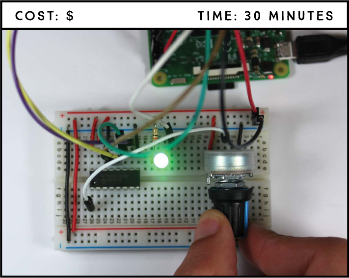
LED Dimmer Switch
In this project, you’ll build a light dimmer by controlling the brightness of an LED using a potentiometer. The power in this project lies in your ability to read analog inputs with the Raspberry Pi and output pulse-width modulation signals. These will be incredibly useful skills in future projects and in your Pi learning.
PARTS REQUIRED
Raspberry Pi
Breadboard
10 kΩ potent iometer
MCP 3008 chip
5 mm LED
330 Ω resistor
Jumper wires
INTRODUCING POTENTIOMETERS
Potentiometers are like power dials and are used in a wide variety of applications in your daily life, such as controlling the volume of the radio, adjusting the brightness of a display, setting the speed on a fan, and much more. The potentiometer you’ll use in this project is shown in Figure 3-1.
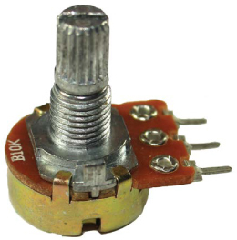
FIGURE 3-1: A 10 kΩ potentiometer
A potentiometer, also referred to as pot, is a manually adjustable variable resistor. This means that you can change the amount of resistance it applies to a circuit by rotating the knob, changing the amount of current reaching a particular component.
A potentiometer has three pins, as shown in Figure 3-2. The two outer pins, shown in blue and red, are connected to a resistive element, while the third, shown in black, is connected to a conductive adjustable wiper.
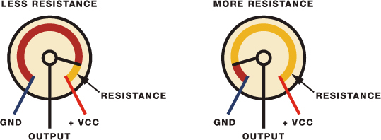
FIGURE 3-2: How a potentiometer works
The position of the wiper determines how much resistance is in the circuit. In this project, you’ll control the resistance in the circuit to make the LED brighter or dimmer.
READING ANALOG SIGNALS WITH RASPBERRY PI
The Raspberry Pi GPIOs can read only digital signals, which means they can read either HIGH (3.3 V ) or LOW (0 V ) but nothing in between. However, the potentiometer is an analog input, and rotating the knob changes its output voltage from 0 V up to 3.3 V. You want the Pi to be able to read all the values in between—like 1 V, 1.4 V, 1.8 V, and so on—so you have gradations of light, not just on and off. For this, you need to convert the analog signal to digital with an analog-to-digital converter chip, and then create imitation analog signals using pulse-width modulation. Let’s go over these two topics before you begin your build.
Analog-to-Digital Converters
The analog-to-digital converter (ADC) chip (MCP3008), shown in Figure 3-3, converts the potentiometer analog signals to digital signals.
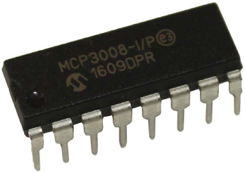
FIGURE 3-3: MCP3008 chip analog-to-digital converter
This chip has 16 pins, 8 of which are analog inputs you can connect to analog devices. The other 8 connect to the Raspberry Pi GPIOs. The chip pinout is shown in Figure 3-4. To identify each pin, orient the chip with the half-circle at the top as shown in the figure.
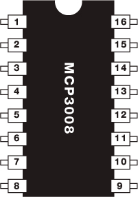
FIGURE 3-4: MCP3008 chip
The following table gives the function for each pin.
PIN |
SYMBOL |
DESCRIPTION |
1 |
CH0 |
Analog input (channel 0) |
2 |
CH1 |
Analog input (channel 1) |
3 |
CH2 |
Analog input (channel 2) |
4 |
CH3 |
Analog input (channel 3) |
5 |
CH4 |
Analog input (channel 4) |
6 |
CH5 |
Analog input (channel 5) |
7 |
CH6 |
Analog input (channel 6) |
8 |
CH7 |
Analog input (channel 7) |
9 |
DGND |
Digital ground |
10 |
CS/SHDN |
Chip select/shutdown input |
11 |
DIN |
Serial data in |
12 |
DOUT |
Serial data out |
13 |
CLK |
Serial clock |
14 |
AGND |
Analog ground |
15 |
VREF |
Reference voltage input |
16 |
VDD |
+2.7 V to 5.5 V power supply |
Pulse-Width Modulation
As we mentioned earlier, the Raspberry Pi GPIOs can be set to either HIGH or LOW, but they can’t output any voltages in between. However, you can output “fake” mid-level voltages using pulse-width modulation (PWM), which is how you’ll produce varying levels of LED brightness for this project.
If you alternate an LED’s voltage between HIGH and LOW very fast, your eyes can’t keep up with the speed at which the LED switches on and off; you’ll simply see some gradations in brightness. That’s basically how PWM works—by producing an output that changes between HIGH and LOW at a very high frequency. The duty cycle is the fraction of the period of time at which the LED is set to HIGH. Figure 3-5 illustrates how PWM works.
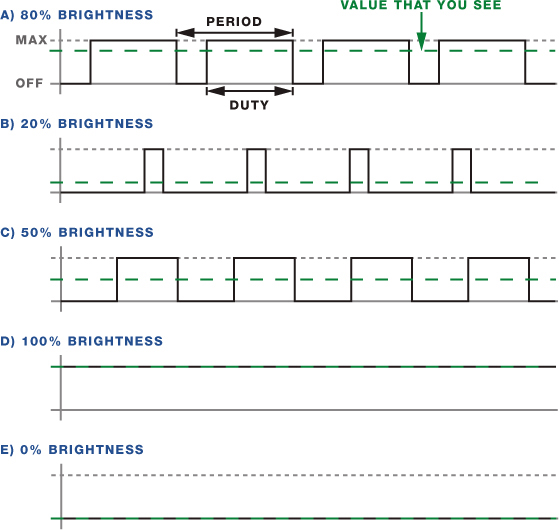
FIGURE 3-5: How PWM works
A duty cycle of 50 percent results in 50 percent LED brightness, a duty cycle of 0 means the LED is fully off, and a duty cycle of 100 means the LED is fully on. Changing the duty cycle is how you produce different levels of brightness.
WIRING THE CIRCUIT
For this circuit you’ll need to connect an LED, the MCP3008 chip, and a potentiometer to the Pi. Follow these instructions to build the circuit, using Figure 3-6 as a reference.
Connect GND to the blue breadboard rail.
Connect 3.3 V to the red breadboard rail.
Insert an LED into the breadboard, connecting the longer LED lead to GPIO 17 through a 330 Ω resistor and the shorter lead to the GND rail.
Place the MCP3008 chip in the middle of the breadboard and connect it as shown in the following table.
MCP3008
RASPBERRY PI
1
Potentiometer middle lead
9
GND
10
GPIO 8
11
GPIO 10
12
GPIO 9
13
GPIO 11
14
GND
15
3.3 V
16
3.3 V
NOTE
Before applying power to the circuit, make sure you’ve connected the MCP3008 chip correctly using the pinout in Figure 3-4, or you could damage the chip.
Connect one of the outer leads of the potentiometer to GND and the other to 3.3 V—it doesn’t matter which lead you use for which connection. Connect the middle lead to MCP3008 chip pin 1 if you haven’t already.
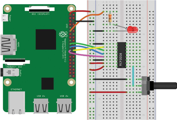
FIGURE 3-6: Circuit to control the LED brightness with a potentiometer
WRITING THE SCRIPT
The Pi reads the analog values from the MCP3008 chip using SPI communication, so you’ll need to enable that first.
From the taskbar main menu, select Preferences ▸ Raspberry Pi Configuration. In the Interfaces tab, enable SPI as shown in Figure 3-7 and click OK.
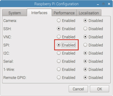
FIGURE 3-7: Enabling SPI communication
Your script needs to be able to do the following:
- Read an analog input value from the potentiometer through the MCP3008 chip.
- Control the brightness of your LED with PWM.
- Change the duty cycle of the PWM according to the input value read from the potentiometer.
Entering the Script
Open Python 3 (IDLE) and go to File ▸ New File to create a new script. Copy the following code to the Python Editor and save the script as brightness_controller.py inside the LEDs folder (remember that you can download all the scripts at https://www.nostarch.com/RaspberryPiProject/):
#import necessary libraries
from gpiozero import PWMLED, MCP3008
from time import sleep
#create an object called pot that refers to MCP3008 channel 0
➊ pot = MCP3008(0)
#create a PWMLED object called led that refers to GPIO 17
➋ led = PWMLED(17)
➌ while True:
#pot.value accesses the current pot reading
➍ if(pot.value < 0.001):
#if the pot value is very small, the led is turned off
➎ led.value = 0
➏ else:
#change led brightness according to the pot value
led.value = pot.value
#print the pot value
print(pot.value)
#pause for 0.1 seconds
sleep(0.1)
As usual, you start your code by importing the required libraries. Then you create an object called pot ➊ that refers to MCP3008 channel 0, the channel the potentiometer is connected to. Channel 0 corresponds to MCP3008 pin 1, channel 1 to pin 2, and so on.
Setting a PWM Pin and Reading Analog Values
The gpiozero library allows you to control an LED’s brightness with PWM by using a PWMLED object. So at ➋, you create a PWMLED object called led that refers to the pin the LED is connected to, in this case, GPIO17.
To read an analog value using the gpiozero library, you simply get the potentiometer value with pot.value. Remember that pot refers to MCP3008 channel 0. You’ll get decimal values between 0 and 1.
Adjusting the Brightness
To adjust the LED brightness using PWM, you need to change its duty cycle. To adjust the duty cycle, you simply have to attribute a value between 0 and 1 to the led.value, in which 0 corresponds to a fully off LED and 1 to a fully on LED.
In this script, a while loop ➌ that is always True keeps the program running. This loop is constantly checking the potentiometer values: if the value read from the potentiometer is below 0.001 ➍, the duty cycle is set to 0, which turns your LED off ➎. Otherwise, the code enters the else block ➏, in which the duty cycle changes according to the value read from the potentiometer.
Running the Script
Press F5 or go to Run ▸ Run Module to run the script. Now you should be able to rotate the potentiometer to control the brightness of the LED.
TAKING IT FURTHER
Knowing how to read analog values and control output pins with PWM opens you up to a huge variety of projects. Give some of these a try for starters:
- Control several LEDs with the same potentiometer.
- Build a bar graph of LEDs that you can control with a potentiometer.
- Control the blinking speed of an LED using a potentiometer.