
3
POLYGONS: HOW 2D BECOMES 3D
As a kid, one of my favorite movies was Tron. Once the hacker was sucked into computer world, it had the most amazing graphics ever. Gone were the blocky and flat pixel sprites of the home video games I’d played. This movie had cool polygon characters and objects that were fully three dimensional. I had never seen anything like it. We were looking at the future.
The very first graphics program, SKETCHPAD, used polygonal modeling. This is the oldest method of creating a computer-generated 3D model. And it’s also the easiest for many people to grasp when just beginning to create in computer-generated 3D environments. Though there is a lot more refinement because of advances in both processing power and the math used, the computer graphics you see on any screen today are still polygons. Even if other methods of modeling are used, models are usually converted to polygons to make images out of them.
Understanding Polygons
When you first opened up your 3D application, it might be that one of the first things you did was to create a polygon primitive. These are instant 3D objects. If you have any art background at all you know you can do a lot with them. There are several types of primitives: cube, sphere, cylinder, etc. Starting with one of those, say a cube, let’s break it down into its parts. The cube is made up of six square sides. Each square is made up of lines, and there are also four corners. Going from understanding these grade-school basics to being familiar with computer-generated models made from polygons is mostly just a trip through a glossary.
The square sides of the cube are polygons. The inside area of a polygon is generally called the face, though some applications call it a polygon. The lines which bound that face are called edges. When talking about the corners of the polygons, we’re more concerned about the points which make up those corners than the angles. Those points are called vertices, or in the singular, vertex. So: face, edge, vertex. These are the basic building blocks of polygons.
To dig a little deeper, let’s break these 3D models down into their dimensions. A vertex has no length, width, or height. Zero dimensions. A line has one dimension: length. A polygon has two dimensions: width and length. And a cube has all three: length, width, and height (Figure 3.1).
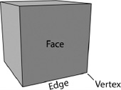
Figure 3.1 A cube.
Polygons don’t have to be just squares. They can be made up of any number of edges and vertices (and there is always the same number of vertices as edges), three at least. You need three to make a face, because that makes a triangle. Now triangles, because they are so simple, are easy for the computer to deal with. This makes them ideal for game engines, since they need to render all those 3D models to the screen as you are trying to get your knight to whack a goblin while healing a friend at the same time (Figure 3.2).
Even a four-sided polygon is unlikely to be a square. Their edges can be all different lengths. Four-sided polygons are called quads, short for quadrangle. Quads are another important polygon in modeling. They stack together in a neat, orderly grid and require only one diagonal edge to break them up into simple triangles. For these reasons, and a few others you’ll learn about later, a lot of modelers prefer to use only quads when modeling.

Figure 3.2 A triangle, a quad, and an n-gon.
And then there are the ostracized n-gons. Any polygon with more than four edges is an n-gon. They are more complicated for the computer to work with and less easy to tile neatly.
One last thing to know about polygons is whether they are planar or non-planar.
Imagine building some polygons out of Tinkertoys, with the sticks making up the edges and the connectors being the vertices. So you’ve got a triangle, a couple of quads and some n-gons lying on the floor. With any of your creations that have four or more sides, you can bend up a corner so that part of them is lying on the floor and part of them isn’t. But if you lift any corner of a triangle off the floor, the entire shape comes up.
Think of your floor as a plane (Figure 3.3). In mathematics, planes have no curves. They can go on and on forever straight in each direction. The triangle can only be on one plane. Existing on only one plane is called being planar. Quads and n-gons can be, and ideally are, only planar. But you can bend up a corner and they can become non-planar. Now, not all applications can work with non-planar polygons. If a polygon is non-planar, it can and will sometimes automatically, be broken down into the simpler and more digestible triangles.

Figure 3.3 Non-planar (left) and planar (right) polygons.
Polygon Meshes
Going back to the cube, notice that edges share vertices, and faces share edges and vertices. They are all connected together. Whenever you have a group of polygons like this that form a model, it’s called a polygon mesh. The Master Control Program from Tron was a polygon mesh, and so was Gollum from Lord of the Rings. They can be as simple or complex as you like, having only one polygon or billions. The only limit, really, is your system’s ability to handle the number of polygons you throw at it.
The cube is an example of a closed polygon mesh. This means that all of the edges are being shared by other faces. There is no hole to get inside the polygon mesh. Now think of a mesh of four quads all stuck together in a plane. That would be an open polygon mesh. Each of the edges that are at the outside of an open mesh are generally called boundary or border edges. A good example of an open polygon mesh would be the leaves of plants you see in many games (Figure 3.4). Close inspection of most in game plants will reveal that the leaves have no volume, but are a handful of polygons in a mesh that is shaped and curved like the leaf.

Figure 3.4 The leaves on this plant, with their alpha planes visible, are good examples of commonly seen open meshes.
Starting Your Model
Once upon a time, modeling with polygons was a time-consuming and meticulous process. The position of each vertex had to be manually drawn in, or even programmed in. These days, things are quite a bit simpler. You can start with polygons or entire primitives, but even drawing in a vertex (if you want) is a lot easier.

Figure 3.5 Box modeling in progress.
There are two popular styles of polygon modeling: box modeling (Figure 3.5) and extrusion (sometimes called edge) modeling.
Box modeling is so named because it starts with a box (a cube primitive). Then the artist scales the object, moves (translates) vertices and edges, and adds more faces by adding edges, so that they create the 3D shape the artist wants. You can think of box modeling as sculpting. One advantage is that it tends to make neat grids and is ideal for subdivision modeling (see Chapter 5).
Extrusion modeling can start with an edge or polygon. Then the artist extrudes (see Extruding, page 29) new polygons from that, building the 3D form around its boundary edges (Figure 3.6). This is the type of modeling often preferred by artists who draw a lot and are familiar with contour drawing. A typical starting point is adding edges around a profile drawing of the object being modeled. Once an entire contour is completed, polygons are extruded so that the polygons bound the edge of the silhouette. Some artists start with a polygon and build the ring of polygons around the profile. Another ring of polygons might be formed around the profile from a different side of the object. Then more polygons are extruded from these edges until they meet each other in a mesh that fully depicts the object.
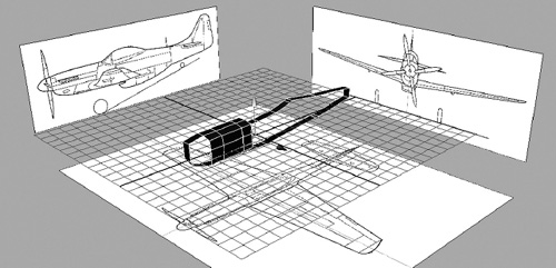
Figure 3.6 Extrusion modeling in progress. The first face which was created when the contour was drawn out with vertices. It was then deleted after the polygons were extruded and another ring of polygons was started.
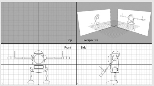
Notice in Figures 3.5 and 3.6 that there are pictures being traced. Both types of modeling often use two or more ortho gonal drawings or photographs imported into the application and then fixed so that the artist can trace them. An orthogonal drawing is a depiction of a character or object without perspective. Think of blueprints. These drawings are usually set up as planes in the front view, side view, and top view of your application (Figure 3.7). When using orthogonal drawings, you need to take care that they each have the same aspect ratio and are set up so the edges of each drawing match each other where they would meet.
Another method common to box and extrusion modeling is mirroring. Instead of modeling each side of the object, only one side is modeled. Then its mirror is duplicated and merged into the mesh. Some applications allow you to see the mirror image as you model. This saves a lot of time and ensures a symmetrical model.
3D modeling on the computer is very much an art form and like any artist you will develop your own way of doing things. It’s a good idea to do a couple of projects using both box and extrusion modeling and see what you’re most comfortable with. Many modelers use both, choosing the method depending on the circumstance. Within those two large classifications of modeling there are lots of ways of adding bulk and detail to your model. Building your personal set of 3D modeling skills takes lots of time and practice.
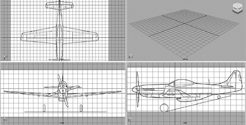
Figure 3.7 Three orthogonal drawings are set up in the top, front, and side views, and as they would be for use in modeling in an application.
Viewing the Object
Let’s take a step back and talk about what you’re actually seeing on the screen. 3D applications differ in a lot of ways, but are also very similar since they are using the same math and are aimed at human operators.
Chances are, that primitive cube you’ve got floating in the virtual 3D space (perhaps seen in four views) on your screen is a wireframe view. A wireframe view shows you all the edges that make it up. They are transparent, so you can see through them. That’s good for being able to see the back part of the model at the same time as the front. But it can be confusing, especially when there is a mess of other objects in the scene. So other applications start with an object that is shaded. This means that the object is colored and there is simple lighting so that you can easily pick out which side is which. It appears solid so that you can’t see behind it. You can also have a combination of shaded and wireframe. This lets you easily see the edges and vertices while remaining dense, or just a little transparent.
There are a few different other views of the object you could choose. One is to have only the silhouette of the object; this is good when you have several things in the scene and you want to see how they occlude each other without any other details getting in the way. Another possibility is to have your object textured. A textured object has the desired image or pattern applied to it so you get an approximation of what it will look like when you render the geometry. This is better for when you’re finishing a project and want to perfect some details.
Editing the Mesh
To begin, you need to be able to select individual components of your mesh, including edges, vertices, and faces. If you started with a primitive, in some applications you will assign the select task to your cursor, and then tell it what component you want to select. At that point you could draw a rectangle (though you may have to specify that type of selection) around a group, or click on just one part at a time. You can also choose the option to select things such as a ring of edges which form a continuous line around your mesh. This is quicker than choosing one edge at a time and useful for moving a whole edge loop.
Once you have something in your virtual grasp, you can move it around or scale it in several ways to form the desired shape. For an example, try selecting a face (or polygon) and pulling it out. You can see how it affects all the polygons around it, changing the shape of your mesh. Now try this with an edge and a vertex. In general, vertices that are not part of the selection do not move. The rest of the model retains its integrity while you create a sharp and steep change of the geometry attached to the changed selection. However, some applications allow you to control how strongly the vertices and polygons surrounding the selected part are affected. When you have polygons from far away feel the effect of changing a face’s position; then the change will create a smoother, less steep slope. The mesh behaves like soft clay, and so this is typically called soft selection (Figure 3.8).
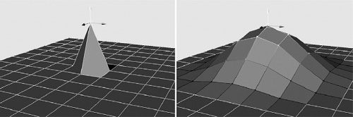
Figure 3.8 An example of regular selection (left) and soft selection of a vertex (right).
Extruding
Extruding is a little different than just pulling and reshaping. It’s a way to add more polygons to a mesh. You can select either an edge or a polygon face (Figure 3.9). When you pull it out, the polygons that shared edges with it will remain the same, but more polygons are automatically created which connect the neighboring polygons to the polygon face you are pulling out. When you do this with a face, you are often creating a bump on a mesh. You could do it again and again to the same face and create a longer, multifaced tube. When you do this with an edge, you are simply pulling out a new polygon. Once again, you can do this more than once on that same edge to create a path of polygons, a method that extrusion modelers use a lot. Having extruded a portion, you can then manipulate it like any other part of your mesh. This is an essential tool for adding detail.
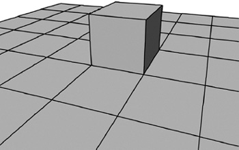
Figure 3.9 Extruding faces and edges.
Controlling Edges and Edge Loops
You may find as you’re adding detail that you need more polygons in general to work with. You can get these by adding edges in strategic places. Be careful as you’re adding edges, as this also adds vertices and can make a quad into an n-gon, even if it appears rectangular. Some applications let you add or subtract a ring of edges that loops around the mesh or a section of the mesh, as in Figure 3.10. These are called edge loops. Adding an edge loop quickly inserts vertices and edges all around the model. Subtracting edges in a similar way is useful if you need to simplify, have artifacts from modeling, or are preparing your mesh to be added to another mesh. Edge loops are important to the overall structure of your model, especially with regard to animating it. You will learn more about edge loops in Chapter 5.
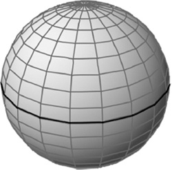
Figure 3.10 An edge loop.
Subdividing and Simplifying
Both adding and subtracting edges can be done across the entire mesh. Adding edges increases the number of vertices as well as polygons. This is called subdividing, and is explained in more detail in Chapter 5. The basic thing to remember is that the more polygons you have, the smoother a curved surface will appear. You can simply subdivide your mesh, or you can subdivide and smooth (Figure 3.11). You can move subdivided edges before you smooth. Smoothing averages out the vertices, so that it has fewer sharp angles. Automatic subdividing in many applications means both the process of increasing the number of polygons by adding edges in between each edge across the entire mesh and then of smoothing.
Likewise, you can decrease the number of polygons in your model by reducing or simplifying the model. To simplify just a small area, you can select individual edges and delete anything unnecessary.
Combining Meshes
It is often easier to sculpt different parts separately before combining them into a single mesh. This is also a great way to build a library of assets for future projects. There are several ways to combine polygon meshes, each with its own advantages.
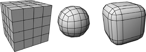
Figure 3.11 A cube. The cube subdivided, subdivided and smoothed, and chamfered. Notice that a similar number of edges was added to the chamfered cube, but they were moved so that the basic cube shape remains, but the corners are beveled.
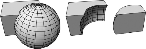
Figure 3.12 Boolean operations, from left to right: union, subtraction, intersection.
One of the simplest to perform is a Boolean operation. Here, you will place your completed meshes together in the 3D space and select the Boolean operation you want. There are three that are typically used: adding (or union), subtracting, and intersection (Figure 3.12). When you add two meshes together, they simply combine to make one mesh. In this kind of combining, the surfaces that are buried into each other still exist. This means that any overlapping polygons still exist, which adds to the complexity of the mesh. When you subtract, you will select the mesh you want to keep first, then the mesh, then choose the Boolean: subtract operation. This will cause the second mesh to “disappear”, removing with it the section of the mesh that overlapped the first mesh. When using the intersect or union operation, only the overlapping areas of both meshes will still appear. Boolean operations are good tools to create more complex models from primitives and can be used on Nurbs, subdivision surfaces, or any kind of 3D model. However, the computer does all of the calculations. This can result in a somewhat messy mesh that requires cleaning up, including deleting faces that may appear on the inside of your model and deleting, adding, or adjusting edges, vertices, and faces to get back to a neater grid-like geometry.
Another way to combine two meshes is to weld them (Figure 3.13). Here, you will specify vertices on the border edges from two different meshes. When you weld them together, those vertices and the edges they make up will combine into one. You could also bridge two border edges. Here, a new edge will be drawn between the selected vertices, so that new bridging polygons are created between the border edges of the two meshes. This bridge has the advantage that you can further subdivide it if needed. Both of these operations can be automated if you have selected two entire border edges, and have them properly aligned and with the same number of vertices.

Figure 3.13 Bridged and welded edges. Notice with the bridged object that new polygons were created to connect the edges. You can add as many divisions as you want to these new polygons.
Polygon Count
The polygon count is an important aspect of a mesh. The larger the polygon count, (Figure 3.14) the more detail it will have. But it will also take more processing power to manipulate the mesh. This translates into time: the more polygons you have, the longer it will take to render. With the right equipment, none of this may be an issue. However, if you are modeling for games, you may very well have limits. In fact, some games have the same model with different levels of detail. Those models farther away from the camera do not need as many polygons to look good. As they move closer to the camera, the game changes them to the more detailed models. This controls the overall polygon count of the animated scene that the computer must render in real time. No matter the goal or resources, it’s a good idea always to keep an eye on how many polygons you are using.
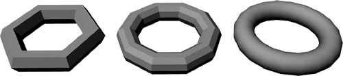
Figure 3.14 Polygon meshes with different polygon counts. Notice that the amount of detail and the smoothness of curves increase as the number of polygons increases.
As you’re modeling, start with a rough sculpture; then slowly add detail only where needed. Quickly adding edges and polygons when you are unsure whether you’ll need them increases the polygon count and also makes your mesh editing trickier. A well-done model has fewer polygons in places of low detail and increases mesh density only where needed. It is usually easier to add polygons than to remove them.
There is more than one way to calculate polygon counts. Sometimes, those that you actually see drawn are those counted. Other times, polygon count has more to do with the vertices. And in other cases, the polygon count is the number of triangles making up the model. Even if you’ve used quads or n-gons, extra edges will be added into the calculation to split them into simpler but more numerous triangles to come up with a polygon count. Many applications make it easy to keep track of polygons, sometimes showing a count on the interface or with a simple click.
Normals
In computer graphics, polygons have a back face and a front face. When a primitive is created, this is easy enough to define: the side of the faces that you can see are the front faces. You can also think of this as the direction that the polygon is pointed in. This is called the normal. Another way to visualize it is to imagine a line that points straight out, or perpendicular to your polygon. It makes your mesh look like a pincushion (Figure 3.15).
Normals are important to calculate how virtual light interacts with the model, as well as several other rendering calculations. Keep track of the directions your polygon faces are pointing in. Normals on a mesh should all be facing the same way. You may find that with some automatic operations such as filling in holes in a mesh, polygons can be created that face in different directions to those near them. In those cases, you will have to fix these before you can move forward with the model.
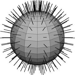
Figure 3.15 A polygon mesh showing its normals.
UV Coordinates
On any type of model you create, you will need to have a way to measure locations on its surface. This is done using UV coordinates. U is measured across one direction and V is perpendicular to that. These locations will allow you to map a 2D image onto your 3D object, giving it a texture.
Aesthetics and Compatibility
There are several things to consider about the look of your model. As mentioned before, many artists prefer to use only quads. Even if you’re modeling for a game, triangles can create sharp angles when there is a lot of detail or curves. Quads tend to reduce this effect. It is easy enough to split them into triangles once you have finished modeling. Polygon modeling is the first step to creating a subdivision surface model. Because the polygons are subdivided automatically, having a mesh that is already a neat grid of quads will make a smoother subdivided model and make animation easier since deforming will be more predictable.
You should also avoid having polygons that are very different in size next to each other. When these are smoothed out using subdividing, or deformed when the model is posed, you may get bumps or ripples. Having more or fewer than four edges originating from a single vertex (such instances are called poles) can cause pinching in a subdivided model. Another common snag in modeling is polygons that are unusually shaped, like T-shaped polygons, or convex a polygon where some of the lines are drawn inward, toward the inside of the face. Some of these strangely shaped polygons may not even be valid in the application you are using.
When you are just getting started, it’s a good idea to follow these conventions. However, with a little experimentation, you may find that the properly used triangle, n-gon, or pole can give you just the surface you need on your model.
Valid Geometry
As you can imagine, there could be several possibilities where your application will not allow certain geometries. Different programs differ in what they can and cannot work with so by keeping in mind the typical rules, you can create a polygon mesh that is easy to export for further development or to sell. Below is a list of things to look out for.
• |
Every vertex must be a part of at least one polygon, as should every edge. You will often get stray vertices when an edge has been deleted. Watch out for these. |
• |
Any vertex can only be used once in the same polygon. |
• |
All edges in a polygon must be connected to each other. |
• |
Only two polygons can share an edge. |
• |
A polygon may not cross itself. |
• |
Some programs do not support convex polygons. |
• |
Do not have a vertex that is the only connection point for two parts of a model (think of a vertex being shared by two cones meeting at their points). |
• |
Avoid edges on top of edges and faces on top of faces. |
• |
Be careful of any holes you leave in a mesh: areas that may appear to be a polygon, but which are simply border edges. |
• |
Valid meshes have all the normals pointing in the same direction. |
Lots of these things may occur when you’re using automatic operations. Be sure to inspect your mesh for them. Many applications have special scripts to pick out bad polygons or polygon meshes. Using these right after important steps in your modeling can help insure that your mesh will be clean and usable.
Simple Polygon Robot
Step 1
Download RobotFront.jpg and RobotSide.jpg from the book’s website, www.3dartessentials.com. Start a project in your application and place the pictures as image planes in your front and side orthogonal views. Make sure they are centered and all parts are vertically aligned, except for the arms, which have been put at different angles in both pictures. The grid can be very helpful for this. If you want to keep the image planes in your perspective view, you can move it back along the orthogonal view’s axis by enough units to put it behind the perspective view’s grid.
Step 2
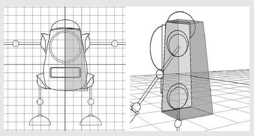
There are two ways to start this. With extrusion (edge) modeling, you will start on the side view. Draw a polygon tracing the main body, using only four vertices. Don’t worry that it doesn’t match the beveled corners exactly. That will come later. Put your vertices a bit outside the bevels, as smoothing will pull surfaces inward. Select the polygon’s face and extrude it in the front view. It will be starting from the center. Pull it to the farthest edge of the main body.
With box modeling, you will create a cube, with one face on the side view plane. Then, still in the side view, select the vertices at the corners and move them in to match.
Do not include the big round top or its border in your cube. Name the shape Body.
Now, no matter how you started you will need to go to the front view and move those corners to match. Select the two vertices on the top at the outside edge and move them into that corner of the main body. It helps to select by bounding with a rectangle to get all of those vertices on the corner. Moving multiple vertices can help to keep things in line. Usually there is also a way to single select more than one by using the keyboard as you select each one with a mouse.
Delete the face that is on the side view plane – the one that is down the center of the robot image in the front view. If you extruded, it’s the one you originally drew.

Step 3
You will want to add more details to make the main body match the drawing more closely. To do this, you will add edges to the box. You can often easily add more edges that go all the way around the model. Insert an edge loop toward the bottom, and one near the middle of the eye. This will make three subdivisions along the width and across the height. Now select vertices and move them into place. Try to select as large a group of vertices as possible to move at once; then start moving smaller groups to tweak.

Step 4
To create a sharper corner for more interest on the top of the head, you’ll need another edge loop. Going from the side view, add an edge loop at the place where the border for the brain case starts in the back. Extrude the face that’s on the top up just a bit to make the border on top, and then extrude the back face for the border and the new skinny face that was made with the top extrusion, once again just a little. With this done, you’ll probably have new faces on the open center by all the newly extruded faces. Make sure you delete these.

Step 5
Create a polygon primitive sphere in the side view. You will want the height axis to be along the axis that the arm will go, so that the “longitude lines” go in that direction. Size it and place it to match the sphere on the right shoulder. Name the sphere Shoulder. For the hip joint, copy the shoulder sphere and place it at the hip. Rotate it 90 degrees so that its height axis points along the leg. Size it so that it is a bit smaller. Name it Hip.

Step 6
Starting on the side view, create a cylinder primitive. Size it and place it so it matches the upper arm limb and is in the middle of the shoulder sphere. Copy the cylinder, and place it on the forearm. Copy again, this time rotating and moving it to the thigh. Resize it to match. Notice that the hip joint as a ball joint would be awkward because of the angle of the thigh. Resize and move the hip joint. It may not match the picture exactly, but that’s okay. It happens sometimes, especially if your image plane is just a sketch. It’s more important that the model be more structurally sound for later rigging. Now copy the thigh cylinder, then move that copy down to become the lower leg. Make sure you name all of the cylinders: UpperArm, LowerArm, UpperLeg, LowerLeg.
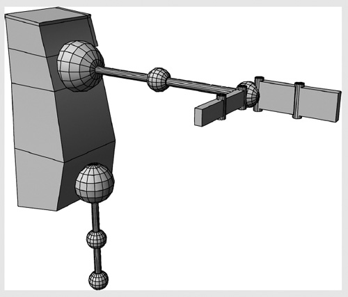
Step 7
Now create a sphere for the elbow, make copies, and place them at the wrist, knee, and ankle. Remember to keep their axes aligned along the arm and leg the same way the shoulder and hip spheres are. Name them accordingly. To create the hand clamp start by making cube primitives, sizing them, and placing them as per the picture, keeping a gap for the hinge joints. The thumb clamp should be a bit narrower than the palm clamp. To make hinges, create little cylinders and place them at the base of the palm clamp and thumb clamp, then between the finger and hand clamp and the thumb and second thumb clamp. Name each shape.

Step 8
Now, just to work with and see in future tutorials, you are going to mirror the main body. Select Body. Because of the way you created the shape with the image planes, along the center of the front plane, Body should already be in place. This is also the reason for deleting the face and having the shape open. There will be some options for mirroring the geometry. Make sure you choose the right axis or else it will mirror in a direction you don’t want. Also, select the option to have the vertices merge. Otherwise, it may merge borders while still keeping those edges and you will find extra vertices and edges down the middle.