The small house movement (http://en.wikipedia.org/wiki/Small_house_movement) is becoming popular with people who want to live simply and have less impact on the environment. Also called micro homes, tiny cabins, and a variety of other creative names, these dwellings are often built on a trailer for portability.
One of the clients from my architectural rendering business is a tiny cabin designer and builder. Jim Wilkins, owner of Tiny Green Cabins, will send me a hand-sketched design with measurements, which I'll model in SketchUp and render to create photorealistic images that he uses to sell the finished cabins. For folks who want to build the cabin themselves, Jim sells a set of construction plans created in Layout, which is a part of the SketchUp Pro package. In this chapter, we'll learn the steps necessary to convert the actual model I used for rendering a tiny cabin into a 3D-printable model as shown in the following image. You may follow along with an architectural model of your own, or one from the 3D Warehouse. This process will be similar for many architectural models:

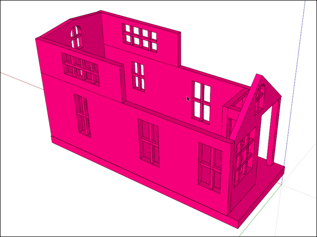
The following screenshot shows the original model that was made for rendering:

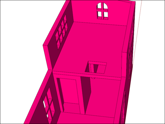
In the following screenshot, we turn the textures off (View | Face Style | Monochrome), so the back faces will show in orange. We can use the Section Plane tool to look inside the model. The Section Plane tool creates a nondestructive cut in the model, allowing you to look or work inside an enclosed space. By right-clicking on the section plane, it can be turned on or off, hidden, and reversed.

At first glance, we can see numerous issues with 3D printing the model. Because we're using the style we created in Chapter 2, Setting Up SketchUp for 3D Printing, we can see numerous back faces showing in orange that will need to be fixed. The panes of glass have no thickness, the cabin is a mass of separate nested groups and components of which many are not solid, and some features are too small to print. For this model, I will not be printing the trailer wheels and hitch, which will simplify the process and make the final print more durable.
For the first print, let's design for FFF printing. I'm going to be using my Solidoodle desktop 3D printer that has a maximum build area of 6" x 6" x 6" (150 mm x 150 mm x 150 mm). The overall length of the cabin is 24" (7.3 m), so with a little simple math (or trial and error) I know that at 1:48 scale, the model will just fit on my printer.
Note
Here's a trick to quickly resize a model to any scale; for example, 1:48—draw a line in empty space 48 mm long. Using the Tape Measure tool, first click on one end then the other end of the line, type 1 mm and hit Enter. SketchUp will ask if it's OK to resize the model, just click on Yes and voila, the model is scaled precisely. This works with any unit of measurement because you're changing the 48-unit-long line to 1 unit long and the rest of the model is scaled to match. If you have trouble with some of the imported components not scaling to match, simply enclose the entire model in a new group before scaling.
Taking into account the requirements of FFF printing, we know that the eaves will not print without support. To minimize support, we'll print the roof separately and since the roof has two separate pitches, we'll print it in two pieces. For the windows, we'll remove the glass and print just the grills for a window-like effect.
Trying to fix this model by making all the components solid, beefing up the thin features, and repairing the windows is doable, but would be a tedious and mentally painful process. There are extensions that attempt to automate the process, but I haven't found any that really work well. One approach that seems to work best is to use the original as a guide while constructing a new, printable model around it.
In this process, we'll create solid shapes that are of the correct thickness for printing, and assemble them like LEGO pieces into the exact shape needed. For features too small to print, we'll exaggerate their size to make them large enough for printing, or simply eliminate them. Using the Outer Shell command, at the end we'll combine all the pieces into a solid, printable model.
Thinking about the minimum features for this printer, let's plan ahead to print this model in full color. To save time then, we'll make sure this model works for both an FFF printer and a full color printer as much as possible. In the end, we'll have one model for each type of printing, each tweaked with the necessary requirements.
After checking the requirements for full color material (http://i.materialise.com/materials/multicolor/design-guide), we can see that the minimum wall thickness is 1.5-2.0 mm, and minimum detail is 0.8-1.0 mm. FFF printers can also work within these guidelines, so we'll keep them in mind while modeling.
The full color printer is powder-based, so we'll want to make the model hollow to save on material costs.
The first thing to do is group the entire cabin and place it on its own layer so that we can quickly hide and show it as needed. To do this, press Ctrl + A to select all of the geometry in the model, then navigate to Edit | Make Group. Open the Layers dialog box by navigating to Window | Layers, and clicking on the plus icon to add a layer. Name it 0 – original (if there other layers in the model, the 0 makes the new layer stay at the top of the layer list, so you can find it easily). Select the group, and in the Entity Info window, set the layer to 0 – original. Now, we can toggle visibility of the original model using the Layers window.
The following screenshot shows this process:

The Hide and Unhide commands can also be used to toggle visibility of groups in the model. Setting these commands to keyboard shortcuts can dramatically speed up your workflow.
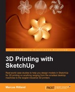
Let's begin modeling! We'll use the trailer bed as a base to provide most of the structural support, so let's make it 5 mm thick. Off to the side, draw a rectangle larger than the trailer, extrude it by 5 mm, and make it a group. Paint it with a bright color to distinguish it from the rest of the model in the next steps, as shown in the following screenshot:
Using the Move tool, grab the top-front corner of the new trailer bed, and place it on the top-front corner of the original trailer. Zoom in closely during this operation to place the geometry precisely as shown in the following screenshot. Notice how the top is aligned, but the new geometry hangs lower to increase the thickness of the trailer bed for strength in the printed product. We can tell the top faces are aligned because of the visible "Z-fighting", which happens when two faces share the same plane and both colors fight for visibility as the model is orbited.

Orbit to the other side of the model where the new geometry is much too large. This is easily fixed using the Scale tool. Select the new group, click on the Scale tool and using only the center-most scale grip on one side, squash the group until it's of the correct size. Using the center-most grip will scale the group along one axis at a time, as shown in the following screenshot. The Push/Pull tool will work for this operation as well, but using the Scale tool saves the extra steps of opening and closing the group:

Use inferencing with the Scale tool to align the new group with the original model as shown in the following screenshot, and then repeat for the last side of the new trailer bed:

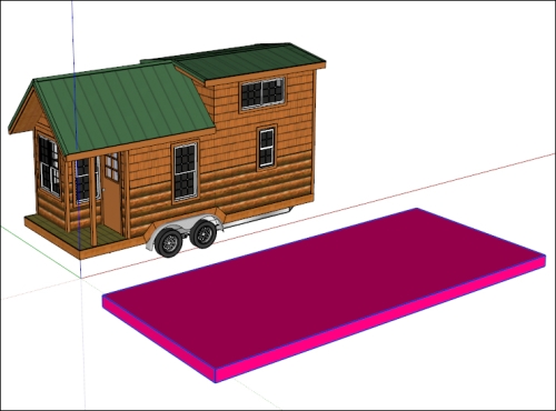
Let's make the exterior walls 3 mm thick. Create a rectangular box 3 mm wide, off to one side, as shown in the following screenshot. Make the box into a group. By copying this group and using it to create new walls in place of the existing model, we'll ensure an even 3 mm wall thickness throughout the model:
Turn off the original model layer so that it doesn't interfere, and position the new wall on the new trailer bed. Turning the original model layer on and off as needed and using the Scale tool just as we did with the trailer bed, align the new wall with the original as shown in the following screenshot. Scale only one direction (length or height) at a time and never along the thickness. This way the walls will all be of a uniform 3 mm thickness:
Copy the new wall to the opposite side of the cabin and repeat the process for each of the remaining walls. Notice that we copy the first wall to create the second, rather than drawing another from scratch. Copy and rotate the first wall by 90 degrees for the end walls.
To make the peaked gables on the end walls, scale the end wall up to the top of the peak, open that group for editing, and draw lines for the peaks, as shown in the following screenshot. Push-pull the excess material away to finish up.

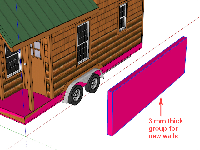
When this step is complete, the walls should look like the following screenshot. Windows and doors will be cut in the next step.

To cut the windows, turn the original model layer on and create a guideline perpendicular to the wall. Use the Move tool along with CTRL to copy and place two guidelines on each window at opposite corners. This creates two points piercing the new wall that we can use to draw a rectangle directly on the new wall and push-pull it by creating a window as shown in the following screenshot:

The next step is to place the window grills. This is one feature that needs to be exaggerated in order to print correctly. At a 1:48 scale, the thickness of the grills in the original model is only 0.2 mm thick—much too thin for printing on the machines we chose. Since the grills are just spanning a short distance, the minimum recommended wall thickness of 1.5 mm should work fine. Draw a square 1.5 mm x 1.5 mm, extrude it up about the height of a window, and make it a group as shown in the following screenshot:

Move it into position, inferencing the midpoint of the grill group to the midpoint on the window. Scale only along the long, vertical axis as needed to fit in the window. Make a copy and rotate it 90 degrees to create the horizontal portion, and then copy these two groups to the other windows, centering them as you go. You'll want to be careful to always make sure the window grill groups are abutting or intersecting with the wall groups, leaving no gaps that will cause problems with printing.
The following screenshot shows what the walls look like with all the windows and doors cut out, and the window grills in place:
The interior walls and loft of the cabin are added using the same method we used for the exterior. Since these walls will not be handled as much, they don't need to be as strong, so we can make them thinner—2 mm will be enough. The interior is shown in the following screenshot:
The next step is modeling the roof. First, draw the roof profile, ensuring a minimum wall thickness of 1.5 mm in all places. In the following screenshot, the overall thickness is 4 mm so that near the eaves the thickness is sufficient. In the following screenshot, notice the 0.2 mm clearance between the eaves and walls, so the separate roof isn't too tight to place on the top:

Push-pull the roof to match the length of the original model. Perform the same steps for the upper roof, and make the vertical walls to connect the space between the upper and lower roof, drawing each portion in a separate group, but combining the vertical walls and the steep roof with the Outer Shell tool.
In the following screenshot, you can see the completed roof assembly, with the rest of the model hidden:

The two roof pitches are kept separate for printing on the FFF printer. Since the two roofs overlap in the center of the cabin, I used the Subtract tool in SketchUp Pro to cut away the portion that was overlapping. You can perform the same action using the Intersect with Model command in SketchUp Make. For more information on the Intersect with Model command, please refer to Chapter 6, Designing a Phone Cradle.
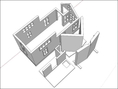
The model is now nearly complete. In the following screenshot, notice how the roofs are positioned for easy printing with no support. The vertical walls connecting the upper and lower roofs are able to be placed flat on the print bed, while the rest of the roof geometry is self-supporting:

While the roofs are in the printing position, we can add more features. The shallow roof on the left has little surface area but a relatively great height. Tall, thin features like these can easily be knocked over by the print head during printing. By adding temporary feet, we can ensure that the roof will be stable for printing. These feet can be cut off with a knife after printing.
Another feature we can add now is stabilizing tabs to the shallow roof. The steep roof has ridges that can grip the top of the walls after printing, but the shallow roof does not have much to keep it from sliding off the walls. By adding tabs as shown in the previous screenshot, the roof is stabilized and the tabs are hidden on the finished model. Adding them while in the printing position allows us to be sure the tabs meet the 45-degree rule for printing overhangs without support.
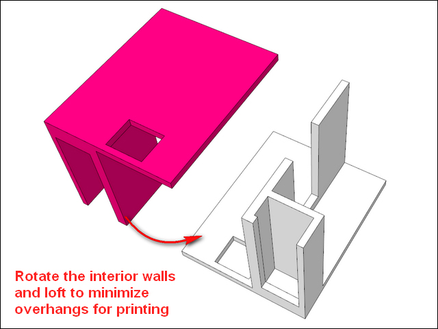
Moving on toward the interior, we can see the loft creates a large overhang that will require a lot of support if printed in place. Select the interior walls and loft, and connect them into one solid with the Outer Shell tool.
By keeping the interior walls and loft separate from the rest of the model, we can print them upside down so that no support is needed, as shown in the following screenshot:
The four sections of the model can be printed all at once on the printer with no extra support, and assembled immediately afterward with little to no hand work. The only thing remaining is to combine the walls, base, and window grill groups into one solid for printing. As usual, make a copy of everything for your historical timeline before performing the operation. This way, if you need to go back and edit a particular part of the model, the separate groups make the job much easier.
In the following screenshot, the model is completed and ready to export for printing on a desktop printer:
In the following three images, you can see the final printed model. All of the parts feel strong, and they fit together well. As a communication tool, this model will definitely work well:


The interior walls and loft group are snapped tightly into place. As an afterthought, I could have printed the interior and the walls with the rest of the model, and printed just the loft floor separately.
You probably noticed that the windows' grills are missing—well, after printing the model twice without good results, I cut them out with a knife.
Remember how you learned tall, thin prints don't work well? A good example of that occurrence is shown in the following image, right after the printer finished making a second print of the cabin:

Notice how some of the windows look fine, but most of the vertical parts of the grills are missing. The tall thin posts easily get knocked over when the print head passes over them. On this second print, I added another horizontal bar across the tall windows to shorten the vertical bars. I also increased their thickness from 1.5 mm to 2 mm, but that still didn't work well. Any larger, and the grill would fill up too much of the window, so I felt cutting them out was the best option.
The tall, thin post on the corner of the porch proved troublesome for the same reason on the first print. Thickening it up to 4.5 mm worked well on the second print.
To save material, I reduced the base thickness to 2.5 mm in the second print from 5 mm in the original model. It still has plenty of strength, but saved significant printing time and material.
Printing this model challenged my skills on the 3D printer. Operating the printer is an art in itself, and having owned my own printer for only a few short months at the time of this writing, I have not learned all the printer settings to tweak for different situations. It is possible by changing some settings that even the windows would have printed well on this model.
Statistics are fun, right? The following are the vitals for this model:
- Printed in ABS plastic with a heated bed and enclosure
- 8 hours of printing time for a complete set of parts
- $2.25 of material, not including the re-print
This troubleshooting and reprinting experience is typical in home 3D printers, and is the reason why sending a model off to a print service can be a much better use of a designer's time. In the next section, this is exactly what we'll do!