
Do you remember as a kid when you first got your own camera? After taking the usual pictures of your dog and the neighbor's fence, you quickly learned how much fun you could have with camera placement, such as a picture of a flagpole from the top of the flagpole or your mom's timeless expression when she found you inside the dryer. Cameras in Max can also offer all kinds of amusing views of your scene.
The benefit of cameras is that you can position them anywhere within a scene to offer a custom view. Camera views let you see the scene from a different position such as from the top, front, or left. You can open camera views in a viewport, and you can also use them to render images or animated sequences. Cameras in Max can also be animated (without damaging the camera, even if your mischievous older brother turns on the dryer).
In the Camera Parameters rollout is a section for enabling Multi-Pass Camera Effects. These effects include Motion Blur and Depth of Field. Essentially, these effects are accomplished by taking several rendered images of a scene and combining them with some processing.
If you're a photography hobbyist or like to take your video camera out and shoot your own footage, then many of the terms in this section will be familiar to you. The cameras used in Max to get custom views of a scene behave in many respects just like real-world cameras.
Max and real-world cameras both work with different lens settings, which are measured and defined in millimeters. You can select from a variety of preset stock lenses, including 35mm, 80mm, and even 200mm. Max cameras also offer complete control over the camera's focal length, field of view, and perspective for wide-angle or telephoto shots. The big difference is that you never have to worry about setting flashes, replacing batteries, or loading film.
Light coming into a camera is bent through the camera lens and focused on the film, where the image is captured. The distance between the film and the lens is known as the focal length. This distance is measured in millimeters, and you can change it by switching to a different lens. On a camera that shoots 35mm film, a lens with a focal length of 50mm produces a view similar to what your eyes would see. A lens with a focal length less than 50mm is known as a wide-angle lens because it displays a wider view of the scene. A lens longer than 50mm is called a telephoto lens because it has the ability to give a closer view of objects for more detail, as a telescope does.
Field of view is directly related to focal length and is a measurement of how much of the scene is visible. It is measured in degrees. The shorter the focal length, the wider the field of view.
When you look at a scene, objects appear larger if they are up close than they would be lying at a farther distance. This effect is referred to as perspective and helps you interpret distances. As mentioned, a 50mm lens gives a perspective similar to what your eyes give. Images taken with a wide field of view look distorted because the effect of perspective is increased.
To create a camera object, you can use the Create
Camera objects are visible as icons in the viewports, but they aren't rendered. The camera icon looks like a box with a smaller box in front of it, which represents the lens or front end of the camera. Both the Free and Target camera types include a rectangular cone that shows where the camera is pointing.
The Free camera object offers a view of the area that is directly in front of the camera and is the better choice if the camera will be animated. When a Free camera is initially created, it points at the negative Z-axis of the active viewport.
A Target camera always points at a controllable target point some distance in front of the camera. Target cameras are easy to aim and are useful for situations where the camera won't move. To create this type of camera, click a viewport to position the camera and drag to the location of its target. The target can be named along with the camera. When a target is created, Max automatically names the target by attaching ".target" to the end of the camera name. You can change this default name by typing a different name in the Name field. Both the target and the camera can be selected and transformed independently of each other.
You can change any viewport to show a camera's viewpoint. To do so, right-click the viewport's title, and select View and the camera's name from the pop-up menu. Any movements done to the camera are reflected immediately in the viewport.
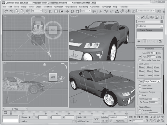
Another way to select a camera for a viewport is to press the C key. This keyboard shortcut makes the active viewport into a camera view. If several cameras exist in a scene, then the Select Camera dialog box appears, from which you can select a camera to use. You also can select a camera and choose the Set View to Selected Camera from the right-click pop-up menu. Figure 18.1 shows two Target cameras pointing at a car. The two viewports on the right are the views from these cameras.
You can turn off the camera object icons using the Display panel. In the Display panel, under the Hide by Category rollout, select the Cameras option. When selected, the camera icons are not visible in the viewports.
Note
Cameras are usually positioned at some distance away from the rest of the scene. Their distant position can make scene objects appear very small when the Zoom Extents button is used. If the visibility of the camera icons is turned off, Zoom Extents does not include them in the zoom. You can also enable the Ignore Extents option in the camera's Object Properties dialog box.
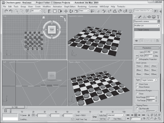
There is no limit to the number of cameras that you can place in a scene. Placing two cameras in a scene showing a game of checkers lets you see the game from the perspective of either player.
To create a new aligned view from the opponent's perspective, follow these steps:
Open the Checkers game.max file from the Chap 18 directory on the DVD.
Select Create

Position the new target camera behind the opponent's pieces roughly symmetrical to the other camera by dragging the camera upward in the Front view.
With the new camera selected, drag the target point and position it on top of the other camera's target point somewhere below the center of the board.
To see the new camera view, right-click the Perspective viewport title and choose View
I was once on a ride at Disneyland when a person behind me decided to blatantly disregard the signs not to take photographs. As he leaned over to snap another picture, I heard a fumbling noise, a faint, "Oh no," and then the distinct sound of his camera falling into the depths of the ride. (That was actually more enjoyable than the ride. It served him right.) As this example shows, controlling a camera can be difficult. This chapter offers many tips and tricks for dealing with the cameras in Max, and you won't have to worry about dropping them.
You control the camera view in a viewport by means of the Camera Navigation controls located in the lower-right corner of the screen. These controls replace the viewport controls when a camera view is selected and are different from the normal Viewport Navigation controls. The Camera Navigation controls are identified and defined in Table 18.1.
Note
Many of these controls are identical to the controls for lights.
You can constrain the movements to a single axis by holding down the Shift key. The Ctrl key causes the movements to increase rapidly. For example, holding down the Ctrl key while dragging the Perspective tool magnifies the amount of perspective applied to the viewport.
You can undo changes in the normal viewports using the Views
Table 18.1. Camera Navigation Control Buttons
Control Button | Name | Description |
|---|---|---|
Dolly Camera, Dolly Target, Dolly Camera + Target | Moves the camera, its target, or both the camera and its target closer to or farther away from the scene in the direction it is pointing. | |
Perspective | Increases or decreases the viewport's perspective by dollying the camera and altering its field of view. | |
Roll Camera | Spins the camera about its local Z-axis. | |
Zoom Extents All, Zoom Extents All Selected | Zooms in on all objects or the selected objects by reducing the field of view until the objects fill the viewport. | |
Field of View | Changes the width of the view, similar to changing the camera lens or zooming without moving the camera. | |
Truck Camera, Walk Through | The Truck Camera button moves the camera perpendicular to the line of sight, and the Walk Through button enables a mode in which you can control the camera using the arrow keys and the mouse. | |
Orbit, Pan Camera | The Orbit button rotates the camera around the target, and the Pan button rotates the target around the camera. | |
Min/Max Toggle | Makes the current viewport fill the screen. Clicking this button a second time returns the display to several viewports. |
Note
If a Free camera is selected, then the Dolly Target and Dolly Camera + Target buttons are not available.
In addition to the Camera Navigation buttons, you can use the Transformation buttons on the main toolbar to reposition the camera object. To move a camera, select the camera object and click the Select and Move button (W). Then drag in the viewports to move the camera.
Using the Select and Rotate (E) button changes the direction in which a camera points, but only Free cameras rotate in all directions. When applied to a Target camera, the rotate transformation spins only the camera about the axis pointing to the target. You aim Target cameras by moving their targets.
Warning
Don't try to rotate a Target camera so that it is pointing directly up or down, or the camera will flip.
Select the target for a Target camera by selecting its camera object, right-clicking to open the pop-up menu, and selecting Select Camera Target.
Because cameras can be transformed like any other geometry, they can also be set to watch the movements of any other geometry. In this tutorial, you aim a camera at a distant rocket and watch it as it flies past us and on into the sky. Zygote Media created the rocket model used in this tutorial.
To aim a camera at a rocket as it hurtles into the sky, follow these steps:
Open the Following a rocket.max file from the Chap 18 directory on the DVD.
This file includes a rocket mesh.
Select Create
Select the camera target, click the Select and Link button in the main toolbar, and drag from the target to the rocket object.
To view the scene from the camera's viewpoint, right-click the Perspective viewport title and choose Views
Figure 18.3 shows some frames from this animation.
Note
The Align Camera command does the same thing for cameras that the Place Highlight command does for lights. A discussion of the Place Highlight command appears in Chapter 19, "Using Lights and Basic Lighting Techniques."
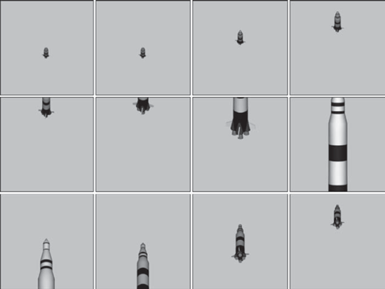
Figure 18.3. Positioning the camera's target on the rocket enables the camera to follow the rocket's ascent.
Cameras can be positioned automatically to match any view that a viewport can display, including lights and the Perspective view. The Views
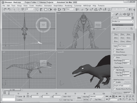
Using the Align Camera tool, you can place a camera so that it points directly at an item or the face of an object, such as the dinosaur's good side (if a dinosaur has a good side). To align a camera with an object point, follow these steps:
Open the Dinosaur.max file from the Chap 18 directory on the DVD.
This file includes a dinosaur model created by Viewpoint Datalabs.
Select Create
With the camera selected, choose Tools
The cursor changes to a small camera icon.
Select the Perspective viewport and click the cursor on the dinosaur's face just under its eye in the Perspective viewport.
This point is where the camera will point.
To see the new camera view, right-click the viewport title and choose Views
Although the camera is pointing at the selected point, you may need to change the field of view or dolly the camera to correct the zoom ratios.
Figure 18.4 shows your dinosaur from the newly aligned camera.
The Align Camera command points a camera at an object only for the current frame. It does not follow an object if it moves during an animation. To have a camera follow an object, you need to use the Look At Constraint, which is covered in Chapter 21, "Animating with Constraints and Controllers."
When a camera is first created, you can modify the camera parameters directly in the Create panel as long as the new camera is selected. After the camera object has been deselected, you can make modifications in the Modify panel's Parameters rollout for the camera.
The first parameter in the Parameters rollout sets the Lens value or, more simply, the camera's focal length in millimeters.
The second parameter, FOV (which stands for Field of View), sets the width of the area that the camera displays. The value is specified in degrees and can be set to represent a Horizontal, Vertical, or Diagonal distance using the flyout button to its left, as shown in Table 18.2.
Table 18.2. Field of View Buttons
Button | Description |
|---|---|
Horizontal distance | |
Vertical distance | |
Diagonal distance |
The Orthographic Projection option displays the camera view in a manner similar to any of the orthographic viewports such as Top, Left, or Front. This eliminates any perspective distortion of objects farther back in the scene and displays true dimensions for all edges in the scene. This type of view is used heavily in architecture.
Professional photographers and film crews use standard stock lenses in the course of their work. These lenses can be simulated in Max by clicking one of the Stock Lens buttons. Preset stock lenses include 15, 20, 24, 28, 35, 50, 85, 135, and 200mm lengths. The Lens and FOV fields are automatically updated on stock lens selection.
Tip
On cameras that use 35mm film, the typical default lens is 50mm.
The Type option enables you to change a Free camera to a Target camera and then change back at any time.
The Show Cone option enables you to display the camera's cone, showing the boundaries of the camera view when the camera isn't selected. (The camera cone is always visible when a camera is selected.) The Show Horizon option sets a horizon line within the camera view, which is a dark gray line where the horizon is located.
You use the Near and Far Range values to specify the volume within which atmospheric effects like fog and volume lights are to be contained. The Show option causes these limits to be displayed as yellow rectangles within the camera's cone.
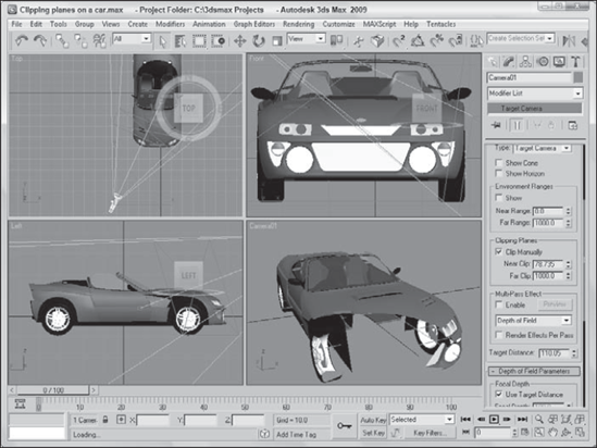
You use clipping planes to designate the closest and farthest object that the camera can see. In Max, they are displayed as red rectangles with crossing diagonals in the camera cone. If the Clip Manually option is disabled, then the clipping planes are set automatically with the Near Clip Plane set to 3 units. Figure 18.5 shows a camera with Clipping Planes specified. The front Clipping Plane intersects the car and chops off its front end. The far Clipping Plane is far behind the car.
Tip
Clipping planes can be used to create a cutaway view of your model.
To understand the Camera Correction modifier, you first need to understand what two-point perspective is. Default cameras in Max use three-point perspective, which causes all lines to converge to a vanishing point off in the distance, but two-point perspective causes all vertical lines to remain vertical.
The visual effect of this modifier is that extra tall objects appear to bend toward the camera when corrected. For example, if you have a camera pointed at a skyscraper, then correcting the camera with the Camera Correction modifier makes the top of the building appear closer rather than having it recede away.
The Camera Correction modifier has an Amount value that lets you specify how much correction to apply and a Direction value that orients the angle of vertical lines in the scene. There is also a Guess button, which automatically sets the correction values for you based on the Z-axis vertical.
Warning
The Camera Correction modifier doesn't appear in the Modifier List in the Modifier Stack, but you can select it from the Modifiers
All cameras have the option to enable them to become multi-pass cameras. You can find these settings in the Parameters rollout when a camera object is selected. Multi-pass cameras are created by checking the Enable button and selecting the effect from the drop-down list. The current available effects include Depth of Field (mental ray), Depth of Field, and Motion Blur. For each, an associated rollout of parameters opens.
Note
The Depth of Field (mental ray) effect option is covered in Chapter 46, "Raytracing and mental ray."
The Multi-Pass Effect section of the Parameters rollout also includes a Preview button. This button makes the effect visible in the viewports for the current frame. This feature can save you a significant amount of time that normally would be spent test-rendering the scene. The Preview button is worth its weight in render speed. Using this button, you can preview the effect without having to render the entire sequence.
Warning
The Preview button does not work unless the Camera view is the active viewport.
The Render Effect Per Pass option causes any applied Render Effect to be applied at each pass. If disabled, then any applied Render Effect is applied after the passes are completed.
Note
You can also apply these multi-pass effects as Render Effects. See Chapter 45, "Using Atmospheric and Render Effects."
The Depth of Field Parameters rollout, shown in Figure 18.6, appears when the Depth of Field option is selected in the Multi-Pass Effect section of the Parameters rollout. It includes settings for controlling the Depth of Field multi-pass effect.
You can select to use the Target Distance (which is the distance to the camera's target), or you can specify a separate Focal Depth distance. This location is the point where the camera is in focus. All scene objects closer and further from this location are blurred to an extent, depending in their distance from the focal point.
Note
Even Free cameras have a Target Distance. This distance is displayed at the bottom of the Parameters rollout.
Within the Depth of Field Parameters rollout, you also have the option to display each separate pass in the Rendered Frame Window with the Display Passes option and to use the camera's original location for the first rendering pass by enabling the Use Original Location option.
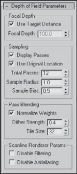
The Total Passes is the number of times the scene is rendered to produce the effect, and the Sample Radius is the potential distance that the scene can move during the passes. By moving the scene about the radius value and re-rendering a pass, the object becomes blurred more away from the focal distance. If you have a fairly tight scene, the default Radius value does not produce very visible results. Try increasing the Sample Radius value and re-rendering. Figure 18.7 shows a scene with Sample Radius values of 1 and 5.
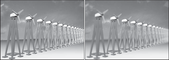
Note
The Depth of Field effect is applied only to rendered scene objects. It is not applied to any background images.
The Sample Bias value moves the blurring closer to the focal point (for higher values) or away from the focal point (for lower values). If you want to highlight the focal point and radically blur the other objects in the scene, set the Sample Bias to 1.0. A Sample Bias setting of 0 results in a more even blurring.
The Normalize Weights option allows you to control how the various passes are blended. When enabled, you can avoid streaking along the object edges. The Dither Strength value controls the amount of dither taking place. Higher Dither Strength values make the image grainier. The Tile Size value also controls dither by specifying the dither pattern size.
With lots of passes specified, the render time can be fairly steep. To lower the overall rendering time, you can disable the Anti-alias and filtering computations. These speed up the rendering time at the cost of image quality.
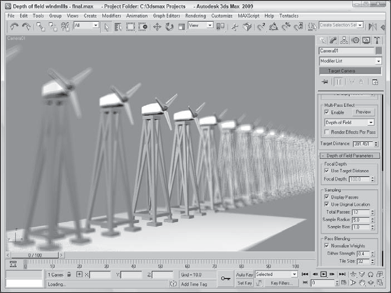
In the dry plains of Southwest America, the wind blows fiercely. Rows of windmills are lined up in an effort to harness this energy. For this example, you use the Depth of Field effect to display the windmills.
To apply a Depth of Field effect to a row of windmills, follow these steps:
Open the Depth of field windmills.max file from the Chap 18 directory on the DVD.
This file includes a windmill object (created by Viewpoint Datalabs) duplicated multiple times and positioned in a row.
Select Create
Tip
You can select both the camera and its target by clicking on the line that connects them.
Select the Perspective viewport, right-click on the viewport title, and select Views
With the Camera selected, open the Modify panel, enable the Multi-Pass Effect option, and then select Depth of Field in the drop-down list.
In the Depth of Field Parameters rollout, enable the Use Target Distance option and set the Total Passes to 15, the Sample Radius to 3.0, and the Sample Bias to 1.0.
Select the Camera viewport, and click the Preview button in the Parameters rollout.
This shows the Depth of Field effect in the viewport.
Figure 18.8 shows the resulting Depth of Field effect in the viewport for the row of windmills.
Motion Blur is an effect that shows motion by blurring objects that are moving. If a stationary object is surrounded by several moving objects, the Motion Blur effect blurs the moving objects and the stationary object remains in clear view, regardless of its position in the scene. The faster an object moves, the more blurry it becomes.
This blurring is accomplished in several ways, but with a multi-pass camera, the camera renders subsequent frames of an animation and then blurs the images together.
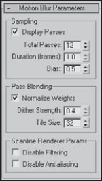
The Motion Blur Parameters rollout, shown in Figure 18.9, appears when the Motion Blur option is selected in the Multi-Pass Effect section of the Parameters rollout. Many of its parameters work the same as the Depth of Field effect.
The Display Passes option displays the different frames as they are being rendered, and Total Passes is the number of frames that are included in the averaging. You can also select the Duration, which is the number of frames to include in the effect. The Bias option weights the averaging toward the current frame. Higher Bias values weight the average more toward the latter frames, and lower values lean toward the earlier frames.
The remaining options all work the same as for the Depth of Field effect.
The Motion Blur effect works only on objects that are moving. Applying this effect to a stationary 2D shape does not produce any noticeable results. For this tutorial, you apply this effect to a speeding car model created by Viewpoint Datalabs.
To apply a Motion Blur multi-pass effect to the camera looking at a car mesh, follow these steps:
Open the Car at a stop sign.max file from the Chap 18 directory on the DVD.
This file includes a car mesh (created by Viewpoint Datalabs), a camera, and a simple stop sign made of primitives. The car is animated.
Click the Select by Name button on the main toolbar to open the Select by Name dialog box (or press the H key). Double-click the Camera01 object to select it.
With the camera object selected, open the Modify panel. In the Multi-Pass Effect section of the Parameters rollout, click the Enable check box and select the Motion Blur effect from the drop-down list.
In the Motion Blur Parameters rollout, set the Total Passes to 10, the Duration to 1.0, and the Bias to 0.9.
Drag the Time Slider to frame 57. This is the location where the car just passes the stop sign.
With the Camera viewport active, click the Preview button in the Parameters rollout.
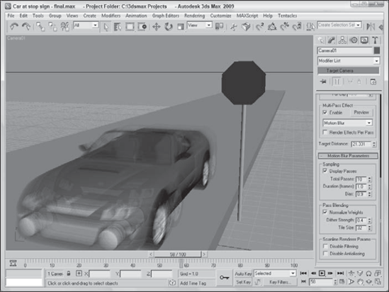
Figure 18.10 shows the results of the Motion Blur effect. This effect has been exaggerated to show its result. Notice that the stop sign isn't blurred. The only problem with this example is that, with the Motion Blur effect enabled, you can't make out the license plate number, so you can't send this speeder a ticket.
Cameras can offer a unique look at your scene. You can position and move them anywhere. In this chapter, you discovered how cameras work and how to control and aim them at objects. With Multi-Pass camera effects, you can add Depth of Field and Motion Blur effects.
In this chapter, you've accomplished the following:
Learned the basics of cameras
Created a camera object and view
Discovered how to control a camera
Aimed a camera at objects
Changed camera parameters
Learned to correct camera perspective with the Camera Correction modifier
Used a multi-pass camera to create a Depth of Field effect
Used a multi-pass camera to create a Motion Blur effect
Although the director typically says, "Lights, camera, action," you've switched the order to be cameras and then lights (action comes with animation later in the book). You just finished cameras, so next you move on to lights.