
When computer-generated 3D images started to appear, it was the raytraced images that really got the wow factor. These images were amazing in their clarity and perfect in reflecting and refracting light through the scene. Raytracing isn't new in Max, but making sense of all the raytracing features can be confusing.
Raytracing in Max can be used with the Default Scanline Renderer using the traditional Raytracing materials and controls, or it can be enabled at the renderer level using the mental ray settings.
To help you generate raytraced scenes, you can also use the mental ray rendering engine. This engine takes the rendering in Max to a new level, enabling you to render your scenes with amazing accuracy, but mental ray doesn't only enable raytracing. It also includes a host of advanced rendering features including caustics and global illumination that are physically realistic.
Raytracing is a rendering method that calculates image colors by following imaginary light rays as they move through a scene. These rays can travel through transparent objects and reflect realistically off shiny materials. The results are stunning realistic images, but the drawback is the amount of time it takes to render using raytrace materials. Scenes with lots of lights and reflecting materials take even longer.
Raytrace materials also support special effects such as fog, color density, translucency, and fluorescence. They include the following rollouts (some of which are similar to the standard materials): Raytrace Basic Parameters, Extended Parameters, Raytracer Controls, SuperSampling, Maps, Dynamic Properties, and mental ray Connection. Figure 46.1 shows the Raytrace Basic Parameters and the Extended Parameters rollouts.
Note
Raytracing can take a long time to complete. As an alternative, you can use a Reflect/Refract map to simulate raytracing.
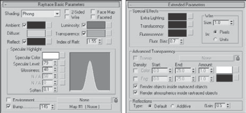
Figure 46.1. Many of the raytrace material settings are the same as those for the standard material.
The raytrace material doesn't have a shader rollout. Instead, shading is determined by a drop-down list at the top of the Raytrace Basic Parameters rollout. The options include Phong, Blinn, Metal, Oren-Nayar-Blinn, and Anisotropic. These shaders are similar to the shaders with the same names for standard materials.
The colors for a raytrace material (except for the Diffuse color) can switch between color swatches and a color value by enabling the check box to the left of the label. The spinners can range between 0 and 100, which equate to black and white. The Ambient color is different from that for the standard material although it is named the same. For raytrace materials, the Ambient value is the amount of ambient light that is absorbed. A setting of white is like locking a standard material's Diffuse and Ambient colors together.
The Reflect color is the color that is added to reflections. For example, if the background color is set to yellow and the Reflect color is red, then the reflections for this object are tinted orange. This is different from the Specular highlight color, which is set in the Specular Highlight group.
The Luminosity color makes an object glow with this color, similar to the Self-Illumination color for the standard material. In fact, when the Luminosity setting is disabled, the text label changes to Self-Illumination.
The Transparency color sets the color that filters light passing through the transparent material. When the color swatch is white, the material is transparent, and when it is black, the material is opaque.
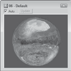
At the bottom of the Raytrace Basic Parameters rollout are two map options for Environment and Bump maps. These maps, which are also included in the Maps rollout, are here for convenience. The Environment map for raytrace materials overrides the global Environment map set in the Environment dialog box. The Environment map is visible only if the Reflect color is enabled or its value is not 0. Figure 46.2 shows a sphere with an Environment map of a mountain meadow applied. The image is from Corel's Photo CD library.
Note
For more information on Environment, Bump, and other maps, see Chapter 17, "Adding Material Details with Maps."
The Extended Parameters rollout holds the settings for all the special material effects that are possible with the raytrace material. Only the Wire settings are the same as the standard material.
The Extra Lighting color swatch increases the effect of Ambient light. Use it to increase the ambient light for a single object or subobject area and to simulate radiosity. Radiosity is a rendering method that creates realistic lighting by calculating how light reflects off objects.
Translucent objects, like wax, lets light penetrate an object, but the objects on the other side are unclear or semitransparent, causing the light to scatter. You can use this effect to create frosted glass. Fluorescence makes materials glow like fluorescent colors under a black light. This happens when a material appears one color when illuminated by another color light. The Fluorescence Bias field, which can range between 0 and 1, controls the amount of this effect that is applied.
The Advanced Transparency group includes a shortcut for the Transparent Environment map. This map is refracted through a transparent object and is visible only if the Environment map is enabled. You can use the lock icon to the right of the Transparency map button to lock the Environment map above with the Transparent Environment map.
Raytrace materials that are transparent can also have Color and Fog Density settings. You can use Color Density to create tinted glass: The amount of color depends on how thick the object is and the Amount setting. The Start value is where the color starts, and the End value is the distance at which the color reaches a maximum. Fog Density works the same way as Color Density and is based on object thickness. You can use this effect to create smoky glass. You also have options to render any objects or atmospheric effects contained within raytraced objects.
The Reflections section offers a Default Reflection Type and an Additive Reflection Type. The Default type layers the reflection on top of the current Diffuse color, and the Additive type adds the reflection to the Diffuse color. The Gain value controls the brightness of the reflection and can range between 0 and 1.
Raytracing can take a long time, but the Raytracer Controls rollout, shown in Figure 46.3, lets you control several Raytracer options that can speed up the process. These options are all local options, including Enable Raytracing, Enable Self Reflect/Refract, Raytrace Atmospherics, and Reflect/Refract Material ID.
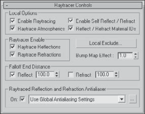
You can use this rollout to turn Raytrace Reflections or Refractions on or off. The Falloff values determine the distance at which the reflections or refractions fade to black. The Bump Map Effect increases or decreases the effect of bump maps on the reflections or refractions.
The Raytraced Reflection and Refraction Antialiaser drop-down list includes three options: Use Global Antialiasing Settings, Fast Adaptive Antialiaser, and Multiresolution Adaptive Antialiaser. This drop-down list is available only if the Global Ray Antialiaser option found in the Global Raytracer Settings dialog box is enabled. The first selection opens the Global Raytracer Settings dialog box.
In the Raytracer Controls rollout, you can also select to include or exclude objects from the effect of a local raytraced object. The Local Exclude button opens the Exclude/Include dialog box that is the same as the Global Exclude/Include dialog box.
Raytrace materials include three additional rollouts: SuperSampling, Maps, and Dynamic Properties. The SuperSampling rollout lets you defer to the Global Settings for changes to the SuperSampler settings for the selected material. The Maps rollout works the same for raytrace materials as it does with standard materials, but the raytrace material includes several unique maps that aren't found in standard materials. The Dynamic Properties rollout for raytrace materials is identical to the Dynamic Properties rollout for standard materials.
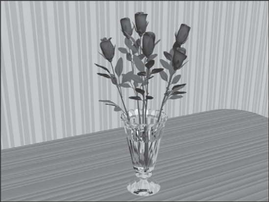
Raytrace examples often include glasses or vases because shiny, highly reflective glass surfaces show off the effects of raytracing best. Zygote Media has an object that is perfect for this task—a vase of roses. (Zygote also created the table used in this tutorial.)
To apply raytrace materials to a vase of roses, follow these steps:
Open the Roses on table.max file from the Chap 46 directory on the DVD.
The file includes some rose meshes in a vase on a table.
Press the M key to open the Material Editor, select the first sample slot, and name the material Raytrace Glass. Click the Type button, and double-click the raytrace material type in the Material/Map Browser. Deselect the Transparency option, and set its value to 100. Set the Index of Refraction to 1.5, and raise the Specular Level to 100. Select the vase object, and click the Assign Material to Selection button.
Select the second sample slot, and name it Leaves. In the Shader Basic Parameters rollout, select the Oren-Nayar-Blinn shader from the drop-down list. Then click the Diffuse color swatch, and select a dark green color. Set the Diffuse Level, Opacity, and Roughness to 100 and the Specular Level to 10. Then select the stems and leaves, and apply this material.
Select the third sample slot, click the Pick Material from Object tool to the left of the Name field, and then click the roses. Doing so loads the material already applied to the roses into the sample slot. Disable the Faceted option, and reapply the material using the Assign Material to Selection button.
Select the fourth sample slot, and click the square button to the right of the Diffuse color swatch to open the Material/Map Browser. Double-click the Wood map to apply this map instead of the Diffuse color and to display the map parameter rollouts. Set the Y-axis Tiling value to 20 in the Coordinates rollout. Then click the Go to Parent button, and in the Blinn Basic Parameters rollout, increase the Specular Level to 75. Name the material Tabletop, and drag the material to the tabletop.
In a graphics program such as Adobe Photoshop, create and save a 200 × 200 image with some repeating colored vertical stripes that can be used as wallpaper. Select the fifth sample slot, and click the map button to the right of the Diffuse color. In the Material/Map Browser, double-click the Bitmap selection. A File dialog box loads, in which you can locate the wallpaper image. In the Coordinates rollout, set the U-coordinate Tiling value to 100 and drag the material to the wall plane object.
Figure 46.4 shows the rendered image.
The raytrace map is an alternative to the raytrace material discussed previously and, as a map, can be used in places where the raytrace material cannot.
The raytrace map includes several similar rollouts and several unique rollouts. In the Raytracer Parameters rollout, the Local Options section lets you select to Enable Raytracing, enable Raytrace Atmospherics, Enable Self Reflect/Refract, and use Reflect/Refract Material IDs. The Trace Mode determines how the rays are cast through the scene. Options include Auto Detect, Reflection, and Refraction. You can also use the Environment Settings or specify a color or map to use for the Background.
The Local Exclude button opens the Exclude/Include dialog box, where you can select which items to include or exclude in the raytracing calculations. The Raytracing Antialiasing drop-down list is enabled using the Global Raytracing Settings dialog box.
Note
You set global raytracing options using the Rendering
The Attenuation rollout lets you select from one of several Falloff Types. The options include Linear, Inverse Square, Exponential, and Custom Falloff. You can also set values for the Start and End distances. The Custom Falloff type lets you set a graph by adjusting Near, Far, and two Control values.
The Basic Material Extensions rollout lets you set the Reflectivity/Opacity Map and its strength. You can also set a Basic Tinting color or map. The Refractive Material Extensions rollout includes settings for specifying the Color Density (Filter color) and Fog.
When you use the Default Scanline Renderer, raytracing is added to a scene to be rendered by applying the Raytrace material found in the Material Editor. Applying a raytrace material to an object sets the local raytracing parameters for the object to which the material is applied, but other settings determine how the raytracing is applied globally to a scene. These settings are found in the Raytracer Global Parameters rollout of the Raytracer panel of the Render Scene dialog box, shown in Figure 46.5. You access it directly using the Rendering
Note
The Raytracer Settings and Raytrace Global Include/Exclude options in the Rendering menu are available only if the Default Scanline Renderer is assigned in the Render Scene dialog box.
Figure 46.6 gives you an idea of what is possible with the raytrace settings. The scene includes several crystal birdbaths with a raytrace transparent material applied. The image on the left was rendered without enabling raytracing, and the image on the right has raytracing enabled. Both were rendered using the Default Scanline renderer. Notice that the reflections are much more pronounced in the raytraced image.
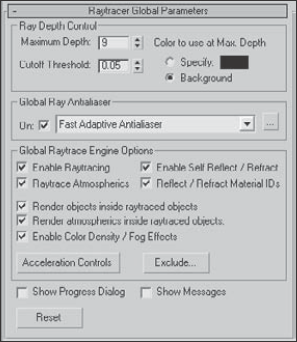
Figure 46.5. The Raytracer Global Parameters rollout includes raytracing settings that affect the entire scene.
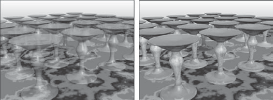
Figure 46.6. This simple scene of crystal birdbaths was rendered without raytracing (left) and with raytracing (right).
Suppose you have a scene with two mirrors that face one another. If the raytracer is allowed to track the bouncing of light rays through the scene, then it never completes, because some light rays would bounce back and forth off the mirrors and never end.
The Maximum Depth setting tells the raytracer how long to follow each ray, or you can set a Cutoff Threshold. (Lower numbers speed up render times at the expense of quality.) You can also specify a color (or select to use the background color) to use for rays that reach the Max Depth, which is useful for identifying lost rays. Lost rays are raytraced lines that don't bounce as expected and can result in a less-than-accurate solution.
Warning
The movement of a ray through the scene depends on the face normals. If the normals are flipped or pointing in the wrong direction, then the results are unpredictable.
The Global Ray Antialiaser group includes a drop-down list with two options: Fast Adaptive Antialiaser and Multiresolution Adaptive Antialiaser. These two options open separate dialog boxes, shown in Figure 46.7. The Fast Adaptive Antialiaser is quicker than its partner and offers settings for Blur and Defocus. The Multiresolution Adaptive Antialiaser takes much longer than the other option, but you can limit it with the Threshold and Max Rays values.
Note
If SuperSampling is enabled for a local raytracing material, then enabling a raytracing anti-aliasing option isn't needed, and vice versa, unless you want to apply a blur or defocus effect.
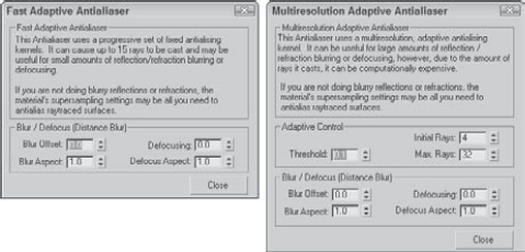
Figure 46.7. Additional anti-aliasing settings are available by clicking the button to the right of the drop-down list.
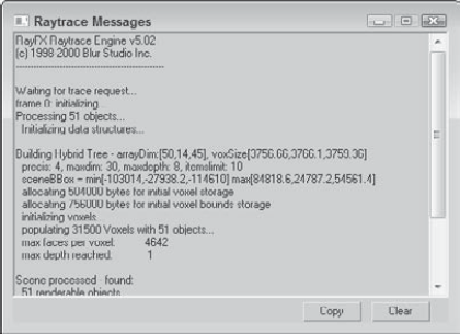
The Options section includes settings to Enable Raytracing, enable Raytrace Atmospherics, Enable Self Reflect/Refract, and Reflect/Refract Material IDs. There are also options to render the objects contained within raytraced objects, to render Atmospheric effects within raytraced objects, and to enable Color Density and Fog effects. The Show Progress Dialog and the Show Messages options let you see the progress of the raytracing engine along with any messages that the raytracing image may output. Figure 46.8 shows an example of the Message dialog box. This dialog box contains some useful information, including the total number of rays traced. From this info, you can determine whether the number of rays is too many or not enough.
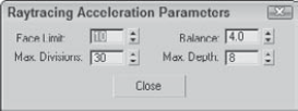
Raytracing can take a long time, but the Acceleration Controls (opened by clicking the Acceleration Controls button), shown in Figure 46.9, offer you several raytracer options that can control the speed of the process. These settings override the existing settings. Before sending rays into the scene, the scene is subdivided into a tree of nodes called a voxel tree. The complexity of this voxel tree determines how long the raytracing solution takes. The Face Limit is the number of faces to include in a voxel node before subdividing. The Balance value defines how the scene gets subdivided. The Max Division sets the size of the voxel subdivisions, and the Max Depth value limits how many times a subdivision takes place.
One of the easiest ways to increase the speed of the raytracer is to reduce the number of objects that it has to deal with. You open the Exclude/Include dialog box for raytraced objects using the Rendering
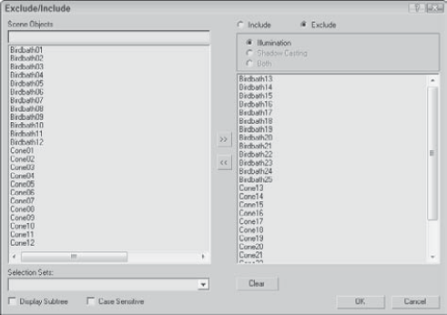
Figure 46.10. The Exclude/Include dialog box lets you select objects to be removed from the raytracer.
The Exclude/Include dialog box includes two panes. The pane on the left lists all the objects within the scene, and the one on the right lists the objects to Include or Exclude, depending on which option is selected.
Note
You use the same Exclude/Include dialog box to exclude objects from the effects of lights.
If you're accustomed to using the Default Scanline Renderer and you're wondering if the mental ray rendering engine is good for you, the answer is yes. Actually, you should try a couple of test renderings first and play with the different settings, but in working with mental ray, I've been amazed at its results. One of the chief benefits of mental ray is its speed. It can render a fully raytraced scene in a fraction of the time without sacrificing quality.
Note
mental ray is an external rendering engine that plugs into 3ds Max. It was developed by a company named mental images, so its development is separate from Max. Versions of the mental ray rendering engine also can be found in Maya and Softimage as well as a stand-alone version.
mental ray also includes support for global illumination without your having to enable the Advanced Lighting settings. In addition, mental ray can use all of Max's existing materials without having to use a limited specialized material like the Raytrace material. Each material has a new rollout that lets you specialize mental ray settings.
Note
mental ray can't use the Advanced Lighting settings. mental ray has its own lighting solution that is independent of Advance Lighting.
Note
Many of the available mental ray materials are covered in Chapter 29, "Using Specialized Material Types."
mental ray also includes native support for Area Lights, Shaders, Depth of Field, and Motion Blur. It also includes some specialized lights that offer functionality, such as caustics, that are unavailable in the Scanline Renderer.
To choose mental ray as the renderer for your scene, simply select it from the list of available renderers in the Assign Renderer rollout of the Common panel of the Render Scene dialog box. You can set a different renderer for Production, the Material Editor, and the ActiveShade viewer. To make mental ray your default renderer, click the Save as Defaults button in this rollout.
Once selected as your Production renderer, you don't need to modify any other settings for the renderer to work. The mental ray settings in the Material Editor, Lights category, and Object Properties dialog box enable additional features that mental ray can take advantage of, but they aren't required to render the scene. The current mental ray version is 3.6.
In the Preference Settings dialog box is a panel of global mental ray settings, shown in Figure 46.11. In this panel, you can select to Enable mental ray Extensions. These extensions add some additional controls to several of the various mental ray panels.
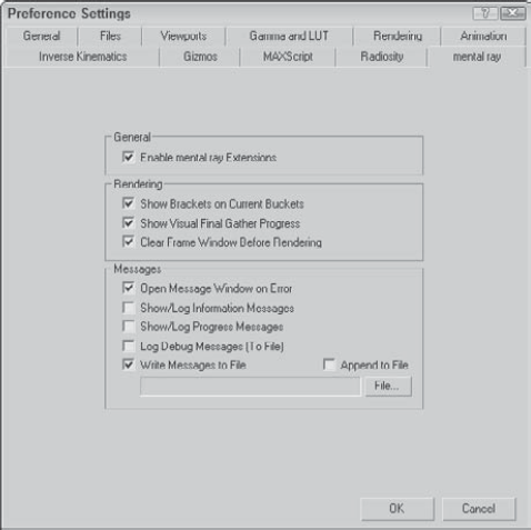
When the Scanline Renderer renders a scene, it progresses one line of pixels at a time down the image, but mental ray renders the image by breaking it up into blocks and rendering a block at a time. The Show Brackets on Current Buckets option displays white brackets around the current block as the image renders.
Note
Multiple white brackets may be visible if you're rendering across a network or using a computer with multiple processors.
The Show Visual Final Gather Progress option displays a rough approximation of the render scene as it is being rendered before waiting for a Final Gather solution. This gives you a quick look at the scene before it computes a Final Gather solution. You can also select to clear the frame before rendering.
The Messages section lets you specify which messages are displayed as the file renders. Options include Errors, Log Information, Log Progress, Debug Messages, and whether to write this information to a file.
If you look in the Lights category of the Create
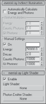
Figure 46.12. The mental ray Indirect Illumination rollout lets you define the light settings for individual lights.
In the Shadows drop-down list is an option to enable mental ray Shadow Maps. These shadow maps are more accurate than normal shadow maps.
If you want to quickly create an outdoor scene and render it using mental ray, then the Daylight system that uses the mr Sun and Sky is an easy quality solution. Before adding the Daylight system to your scene, switch the renderer to mental ray in the Render dialog box. Then add the Daylight system to the scene and in the Modify panel, select mr Sun in the Sunlight drop-down list and mr Sky in the Skylight drop-down list. When you first select the Daylight system, a dialog box appears recommending that you use the Logarithmic Exposure Control with Exterior Daylight Flag enabled. Click the Yes button to enable this control. When your select the mr Sky option, another dialog box appears asking if you want to enable the mr Physical Sky environment map. Click Yes to this also.
If you look in the Environment panel, you can see the mr Physical Sky material applied. This material defines how the sky and ground planes look. The default settings look pretty good.
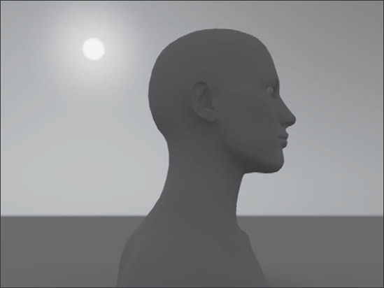
The Daylight system includes controls for positioning the sun in the sky based on a physical location, day of the year, and time of the day. By changing these controls, you can manipulate the sun's position in the sky relative to the scene objects. If the sun appears in the viewport, it is rendered with lens flares, as shown in Figure 46.13.
When a Sky & Sun system is in place, you can ensure that it displays within the viewport if you open the Views
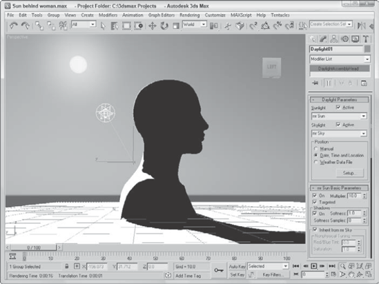
Selecting the sun light object and moving it about the scene or changing the Time and Date parameters automatically updates the background and the scene. This provides a good way to precisely position the sun where you want it, as shown in Figure 46.14.
If you look closely at the Photometric light category, you'll notice another light type sandwiched between the mr Sky and mr Sun lights. The mr Sky Portal provides a way to focus light streaming into an interior space from an external source using a designated portal. This can be thought of as a sky light that causes all Final Gather light rays to be focused on a specific area. It results in a better Final Gather result with fewer light rays. The Sky Portal is direct light giving you one bounce for free if Final Gather is disabled.
To use a Sky Portal, you must have mental ray enabled, include a skylight or a Sun & Sky system, and have Final Gather turned on. Then simply drag over the area where the window is located, and all light rays entering the interior space are focused on those areas defined by the Sky Portal. The gizmo for the Sky Portal is a simple rectangular box with an arrow pointing in the direction of the light rays. If the light rays are pointing outward, you can use the Flip Light Flux Direction option to change their direction.
Tip
For better results for interior scenes using exterior lighting, enable the mr Photographic Exposure Control and use the Physically Based Lighting, Indoor Daylight preset.
Within the mr Skylight Portal Parameters rollout, you can enable or disable the Sky Portal. A Multiplier value and a Filter Color work just like other lights. If the image appears grainy, you can increase the Shadow Samples value to remove any splotchy effect on the walls, but this increases the render time. Within the Advanced Parameters rollout, the Visible to Renderer makes the Sky Portal visible in the rendered image, causing exterior objects to be blotted out.
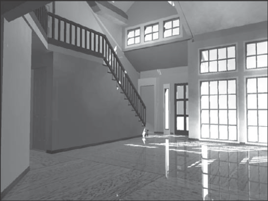
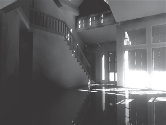
You also can set the Color Source to Use the Scene Environment if you want light to be pulled from the environment map. Sky Portals also support HDRI maps as lighting sources. Figure 46.15 shows a house interior lighted using mental ray, Final Gather, and two Sky Portals.
Light properties for the mental ray renderer include four unique properties: Energy, Decay, Caustic Photons, and Global Illumination (GI) Photons. You can find the settings for these properties in the mental ray Indirect Illumination rollout. Before learning about these properties, you need to understand what caustics and photons are.
Caustics are those strange glowing lines that you see at the bottom of an indoor swimming pool caused by the light refracting through the water. Caustics are common in nature, and now with mental ray, you can add these effects to your scenes. Photons are small bundles of light energy, and like the raytracing rays they are emitted from a light source with a given amount of energy. This energy is lost as the photon travels and as it hits objects in the scene.
The Energy value is the amount of light energy that each photon starts out with, and the Decay value specifies how quickly that energy dissipates. The number of Caustic and GI Photons determines the resulting accuracy of the lighting. More photons yield a better solution, but the greater number also increases the render time substantially. The Multiplier and color swatch lets you set the intensity and color of the caustics.
Figure 46.16 shows a swimming pool with caustics glowing on the side of the wall. The left image shows the pool scene with caustics disabled, and the right image shows them enabled.
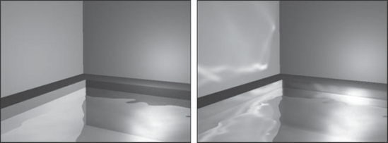
Figure 46.16. This indoor swimming pool scene is rendered without caustics (left) and with caustics (right).
To get caustics to work in your scene, you need to add a Raytrace, Flat Mirror, or Reflect/Refract map to the Reflection map channel for the material that you want to generate caustics.
When using the mental ray renderer, you can see the caustic photons as they are reflected around the room to help you determine the correct settings you need, but these photons themselves can be used to make a good disco ball effect.
Tip
A common way to get a good, crisp caustic effect is to use significantly more photons than you would need for global illumination—on the order of millions of photons—for good results.
To create a disco ball effect using caustic photons, follow these steps:
Open the Disco ball.max file from the Chap 46 directory on the DVD.
This file includes a simple room.
Select Create

Press the M key to open the Material Editor, and select the first sample slot. Select the map shortcut for the Diffuse color, and select the Raytrace map type in the Material/Map Browser. Then drag the Raytrace map in the Map rollout from the Diffuse Color to the Reflection map, and select the Instance option in the Copy Map dialog box that appears. Then enable the Faceted option in the Shader Basic Parameters rollout; set the Opacity to 50, the Specular Level to 95, and the Glossiness to 30; and drag the material to the sphere object.
Select Create Lights
Open the Render Scene dialog box (F10), and switch the Production Renderer in the Assign Renderer rollout of the Common panel to the mental ray Renderer. In the Indirect Illumination panel, enable the Caustics option and the Radius option, and set the Maximum Sampling Radius value to 1.0. Enable the All Objects Generate and Receive Caustics & GI option. Then click the Render button.
Note
If the caustics aren't visible, make sure the Use Advanced Lighting option in the Render Setup dialog box is enabled.
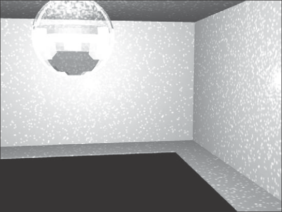
Figure 46.17 shows the resulting disco scene with thousands of lights visible on the walls.
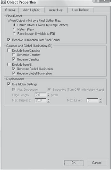
Another "gotcha" when dealing with caustics and global illumination is that each object can be specified to generate and/or receive caustics and global illumination. These settings are found in the mental ray panel of the Object Properties dialog box, shown in Figure 46.18. This dialog box can be opened using the Edit
The mental ray panel in the Object Properties dialog box also includes settings that you can configure how the object is treated during the Final Gather pass. Using the Return Black or Pass Through options, you can make the object unshaded or invisible to the final gather.
Note
The Final Gather settings and the ability to exclude objects from final gather and GI in the mental ray panel of the Object Properties dialog box are new to 3ds Max 2009.
Tip
The Indirect Illumination panel of the Render Scene dialog box includes an option that can be used to cause All Objects to Generate and Receive Caustics and GI. Enabling this option enables these options for all objects regardless of their Object Properties settings.
In addition to the light settings, you can set many of the properties that control how caustics, global illumination, and Final Gather are computed in two rollouts of the Indirect Illumination panel of the Render Scene dialog box, shown in Figure 46.19. These two rollouts are the Final Gather rollout and the Caustics and Global Illumination (GI) rollout.
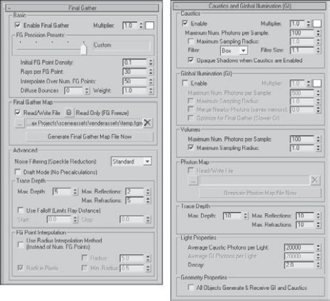
The Final Gather rollout is split into two parts. The top part features a set of Basic settings with several Presets that take the guesswork out of the settings. Simply choose one of the presets from the drop-down list and all the key settings are automatically made for you. The preset options include Draft, Low, Medium, High, and Very High. The Multiplier and color swatch changes the intensity and color of the indirect light. The Weight value sets how much indirect light affect the Final Gather solution.
For caustics and for global illumination, the Maximum Number of Photons per Sample value determines how the caustic photons are blended. A higher value results in more blending and softer edges. The Maximum Sampling Radius value sets the size of each photon. This value is set automatically depending on the size of the scene. However, you can enable the Radius value and enter a new value manually.
The Volumes setting is used by Volume material shaders to set the photon's size. The Trace Depth settings determine the maximum number of reflections and refractions that a photon can take before it is ignored.
Photon and Final Gather maps can take a while to generate for a complicated scene, but once computed, they can be saved and reloaded. These files are saved using the .pmap and .fgm extensions. To generate a photon map, click the Generate Photon Map Now, or to generate a final gather map, click the Generate Final Gather Map Now button.
Note
The Generate Photon Map Now and the Generate Final Gather Map Now buttons are new to 3ds Max 2009.
Final Gather sends out rays to a scene that has computed caustics and global illumination already and computes the light at that location. All these rays are then combined to produce a total lighting picture of the scene and then blended to help fix any lighting abnormalities that may exist in the scene. The Samples value determines how many rays are cast into the scene. The Final Gather lighting pass can then be saved to a file after it is computed.
The core rendering settings for the mental ray renderer are contained within the Renderer panel of the Render Scene dialog box, shown in Figure 46.20. Using these settings, you can increase the speed of the renderer (at the expense of image quality).
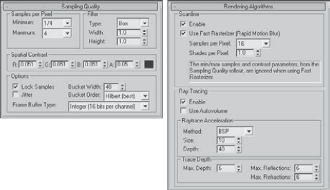
Figure 46.20. The Renderer panel includes several rollouts of settings for controlling the mental ray renderer.
The Sampling settings are used to apply an anti-aliasing pass to the rendered image. These samples can be filtered, and you can control the details of the contrast between the samples. The Bucket Width is the size of the blocks that are identified and rendered. Smaller buckets do not take as long to render and provide quicker feedback in the Render window.
The mental ray renderer uses several different algorithms, and you can specify which ones to ignore in order to speed up the rendering cycle. If a needed algorithm is disabled, the features that rely on that algorithm are skipped. You can also set the Trace Depth for Reflections and Refractions and control the Raytrace Acceleration values.
The mental ray renderer also includes many additional features that you can take advantage of, including Depth of Field, Motion Blur, Contours, Displacement, and Camera Shaders. The settings for these additional features are located in rollouts at the bottom of the Renderer panel. For example, if you add the Glare map to the Output map in the Camera Shader section, then you can get a strong glare from light in the scene, as shown for the house interior in Figure 46.21.
Complex scene can have hundreds of objects and when rendered in mental ray, single frames can take several hours to render. This can make it tough to get previews to test lighting and atmospheric effects. If you know that the objects look fine, then you can use the mental ray proxy object to replace multiple objects or a single high-resolution object with a proxy.
Note
The mental ray Proxy feature is new to 3ds Max 2009.
To use a mental ray proxy object, add a mr proxy object to the scene using the Create
Note
You can only select the source object in the Modify panel.
When the source object is selected, you can save the object to a file. Source objects are saved as .mib files. The object is then displayed within the scene as a point cloud or as a bounding box and a preview of the source object is displayed in the Parameters rollout. You also can change the number of vertices that are displayed in the viewports.
When the scene is rendered, the source object file is read in and used for the render.
If you're looking for a rendering option that perfectly calculates reflections, refractions, and transparencies, then raytracing is what you need. Raytracing settings can be set globally and applied to selected materials using materials and maps. And when raytracing needs an additional push, the mental ray renderer can be selected to render the scene.
In this chapter, you accomplished the following:
Learned about the global raytracing settings
Explored the raytrace material
Worked with raytraced maps
Learned to enable the mental ray renderer
Created mental ray lights
Worked with caustics and photons
Used mental ray proxies
Now that I've told you how to overload the rendering engine, the next chapter offers a way to get some help by batch rendering and rendering over the network.