
Chapter 14. 802.11g: The Extended-Rate PHY (ERP)
When wireless LANs first entered the mainstream computing consciousness, there was one practical choice. 802.11b had recently been standardized, and offered the prospect of near-Ethernet speed, which, to be fair, by that point was not very fast at all. As 802.11a emerged from the laboratory into commercially-available chipsets, users had a desire to obtain higher speeds than 802.11b, while retaining backwards compatibility with the installed base of 802.11b hardware. The result is 802.11g, which offers a headline bit rate comparable to 802.11a while still operating in the microwave band. By working at slightly less than half the frequency, 802.11g devices have better range than the 5 GHz 802.11a devices.
802.11g is not a revolutionary specification. In fact, if you read the new clauses added by the specification, it is clear that it uses much of the existing work done elsewhere. The new physical layers it specifies are built on existing work, and there are only slight modifications. Most of 802.11g is occupied with providing backwards compatibility.
802.11g Components
802.11g is really several physical layer specifications in one. It adds one umbrella clause for the Extended Rate PHY (ERP). However, there are several different “flavors” of ERP:
- ERP-DSSS and ERP-CCK
These modes are backwards compatible with the original direct sequence specification (1 Mbps and 2 Mbps) described in Chapter 11, as well as the 802.11b enhancements (5.5 Mbps and 11 Mbps) described in Chapter 12. To retain backwards compatibility, a few minor changes are required.
- ERP-OFDM
This is the major mode of 802.11g. It is essentially running 802.11a in the ISM frequency band (2.4 GHz), with a few minor changes to provide backwards compatibility. It supports the same speeds as 802.11a: 6, 9, 12, 18, 24, 36, 48, and 54 Mbps. Speeds of 6, 12, and 24 Mbps are mandatory.
- ERP-PBCC
This is an optional extension to the PBCC standard provided in 802.11b, and provides data rates of 22 Mbps and 33 Mbps. Although it is part of the standard, it is not implemented by most major chipsets in the market, and is not widely used.
- DSSS-OFDM
This a hybrid scheme, which encodes packet data using the DSSS headers, and OFDM encoding of the payload. Part of the reason for developing this implementation was for backwards compatibility. Although the body is OFDM-modulated and unintelligible to 802.11b, information in the headers is able to provide information on the duration of the packet. It is optional, and not widely implemented.
Any device that implements 802.11g is required to support a few mandatory modes. For backwards compatibility, 802.11g devices must support DSSS modulation (802.11) at 1 and 2 Mbps, and CCK modulation (802.11b) at 5.5 and 11 Mbps. Basic OFDM support is required, and all 802.11g stations are further required to support OFDM modulation at 6, 12, and 24 Mbps.
Compatibility Changes
The mandatory modes in 802.11g are slight modifications of existing physical layers, with a few minor alterations made for backwards compatibility. The modifications required of 802.11g stations assist coexistence with older implementations. They are not changes to the existing specifications. An 802.11b card will work as it always has. The only difference is that an 802.11g card will have a few features not present in 802.11b.
802.11b devices implement two different specifications: the original, slow direct sequence (DSSS) from the initial 802.11 standard, and the high-rate complementary code keying (CCK) PHY from 802.11b. 802.11g adopts both of those standards, and makes only a few minor changes. Naturally, any 802.11g station must be able to hear not only older stations but other 802.11g stations, so any 802.11g-compliant station must support all the preambles and synchronization found in 802.11g. More significantly, 802.11g stations must support the short preamble because it helps a great deal in maintaining high throughput. 802.11g radios are required to be more sensitive to signals as well.
802.11g devices must also implement ERP-OFDM, which is based heavily on 802.11a. In fact, it looks almost exactly like 802.11a, with a few obvious changes. Most notably, 802.11g adopts the frequency plan of 802.11b, so there are still only three ostensibly nonoverlapping channels for use. (See Chapter 13 for the adjacent-channel overlap map; the same note about three mostly nonoverlapping channels applies to 802.11g as well.) It also uses interframe spacing and slot times that are compatible with older ISM-band 802.11 stations. Regulatory structures may be different around 802.11g and 802.11b, however. Japan allows 802.11b operation in channels 1-14, but 802.11g is only allowed on channels 1-13.
Protection
One of the major differences between 802.11b and 802.11g is protection, which is required because of an asymmetry between the chipsets that implement the specifications. One of the problems faced by the designers of 802.11g is that it uses a different modulation scheme than 802.11b. 802.11g chips are built with backwards compatibility, and have no problem receiving and decoding an 802.11b signal. As is normally the case in technology, the converse is not true. 802.11b chipsets have no way of making sense of the higher-speed 802.11g transmissions. Part of the solution is to require that 802.11g stations transmit at a rate supported by all stations in basic service set. If an AP is to serve both 802.11b and 802.11g stations, it will need to send Beacon frames at a frame data rate of no higher than 11 Mbps.
The second part of the solution is to avoid interference between 802.11g and 802.11b networks. To ensure that 802.11b stations are aware of 802.11g transmissions, 802.11g specifies a protection mechanism to “protect” 802.11b stations from interference. The basic operation of the protection mechanism is shown in Figure 14-1. To avoid interference during the transmission of the OFDM frame and its acknowledgment, a slower frame is sent to update the NAV. There are two main protection modes. More commonly, 802.11g stations will use CTS-to-self protection, as shown in Figure 14-1 (a). When a station has a frame for transmission that needs protection, it will transmit a CTS frame with a receiver address of its own MAC address; that is, the destination of the CTS frame is the station itself. In the CTS, it will update the Network Allocation Vector (NAV) to tell other stations using the physical medium that it will be using the radio link for the time necessary to transmit the CTS, the OFDM-modulated frame, and an OFDM-modulated acknowledgment. Although the station sends the CTS to itself, all stations on the network are required to listen to CTS frames and update the NAV accordingly. The CTS frame is sent at the maximum speed it can be, using a modulation that can be received by all stations. Throughput may suffer a significant hit as a result of this exchange. A maximum Ethernet-size data frame and its acknowledgment require 294 microseconds at the highest speed, but the CTS to clear out the network requires at least 107 microseconds, and possibly more than 200 microseconds if long preambles are in use.
Figure 14-1 (b) shows the second mechanism, which is a full RTS/CTS exchange. Full RTS/CTS exchanges are more robust against hidden nodes, but come with a cost in network capacity. As in the CTS-to-self case, the compatibility frames used to reserve the medium may be have a transmission time comparable to or longer than the data. Both the RTS and CTS frames will take 100 microseconds, while a maximum-size data frame and its ACK only require 300 microseconds. Based on calculations of the time required for the extra RTS, I estimate that the use of full RTS/CTS exchanges versus CTS-to-self to be a reduction of approximately one third in overall data throughput.[64]
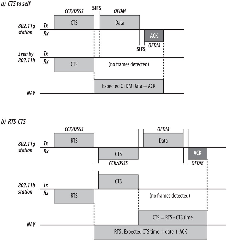
To ensure that the protection frames are received and processed by all stations on the network, protection frames are transmitted using 802.11b rules. They may be transmitted using phase shift keying at 1 Mbps or 2 Mbps, or CCK at 5.5 Mbps or 11 Mbps. Any 802.11b station will be able to understand these modulations, and can update its virtual carrier sense accordingly. Figure 14-1 shows this by labeling the transmission modulation, and only showing the compatible modulations as received by an 802.11b station.
Tip
Only the protection frames are required to be transmitted at the 802.11b-compatible data rates. Protection does not require 802.11g stations to use a slower data rate for the payload data, as is commonly asserted.
Protection is activated whenever there is a need to ensure 802.11g stations do not interfere with 802.11b stations. One obvious case in which this happens is when an 802.11b station associates with an AP. All the 802.11g stations associated with the AP will then start using protection to ensure that the 802.11b station does not suffer from or cause interference. Protection is also activated in the less obvious case of a co-channel AP with 802.11b-only traffic. Because the two co-channel APs share the same physical medium, an 802.11b station using the same channel on a different AP also triggers protection.
Protection is controlled through the ERP information element in Beacon frames. 802.11g adds a Use Protection bit in to an information element in the Beacon. When the bit is set, stations must use protection. When a non-802.11g-capable station associates to a wireless LAN, the protection bit will be set. The station responsible for sending the Beacon is also responsible for deciding whether to activate protection. In infrastructure networks, the protection activation is handled by the access points; in independent networks, it is the Beacon generator. Protection is activated when a non-802.11g station associates with the network, as well as when non-802.11g-capable stations are transmitting in the area. Non-802.11g-capable stations may be deduced by the reception of a management frames, including Beacons and Probe Responses, from an overlapping network that does not indicate the data rates supported by 802.11g.
Beacons in 802.11g networks can also control the preamble length for protection purposes. In the ERP information element, the Barker Preamble Mode bit can be used to tell associated stations whether to use the long preamble or short preamble. If all the stations associated to a network are capable of short preambles, the Barker Preamble Mode bit will be set to zero, and all stations will use short preambles for efficiency. Once a station that is not capable of short preambles associates with the network, however, the bit will be set to one, and all protection frames will use long preambles.
As with most other technology that is required to be backwards compatible, 802.11g can suffer for it. If protection is not enabled, 802.11a and 802.11g throughput is identical. Once protection is activated, however, my calculations showed it to be very roughly 50%, depending on the ratio of TCP data segments to TCP ACKs. Transmitting a full-size 1,500 byte Ethernet frame over 802.11 requires 428 microseconds for both the frame and the 802.11 acknowledgment. When CTS-to-self protection is used, the transmission time jumps to 557 microseconds; RTS/CTS adds further bloat, and requires 774 microseconds for the same transmission. Avoiding the need for protection is one of the reasons that many 802.11g access points offer the ability to accept associations from 802.11g-capable stations only. By shunning stations that are not capable of 802.11g speeds, there is an increased probability that protection can remain disabled. Of course, a station that is shunned may very well find a different network that can accommodate it on the same channel, which would still trigger the activation of protection.
Tip
Although 802.11a and 802.11g are capable of the same speed, the extra transmission time required for protection may cut payload data throughput by half.
Protection is not required for the ERP-PBCC and DSSS-OFDM physical layers. As shown in Figure 14-2, both of them begin with an 802.11b-compatible header, and therefore the virtual carrier sense and NAV are updated without needing to send extra frames. An 802.11b station will receive the header and update the virtual carrier sensing mechanism based on the contents of the header. No transmissions will be allowed until the medium lock expires. Although the 802.11b station cannot detect the body of the frame, it is prevented from interference by the header. There is a cost to using ERP-PBCC or DSSS-OFDM. In a sense, they are always using protection because they use a much slower header. Both ERP-PBCC and DSSS-OFDM have, at minimum, 96 microsecond headers that can never be dropped. In contrast, the common ERP-OFDM mode must use the same header on a CTS frame that takes 107 microseconds to transmit, plus a 10 microsecond SIFS gap. However, ERP-OFDM needs to pay the penalty only when protection is required, while the optional modes always need to suffer the hit.

ERP Physical Layer Convergence (PLCP)
The ERP PHY’s convergence layer is quite complicated. Due to the plethora of operational modes, there are a number of different ways that frames will be bundled up for transmission by the radio interface. Each of the modes described at the start of the chapter has its own physical layer framing.
ERP-OFDM Framing
This mode is the meat of the specification. All stations are required to implement it, and it is what is colloquially meant by “802.11g support” because most stations default to using it. In practice, understanding ERP-OFDM physical framing will provide you with the understanding of most 802.11g transmissions in the air.
The format of the ERP-OFDM frame at the physical layer, shown in Figure 14-3, is nearly identical to 802.11a. ERP-OFDM uses an identical logical protocol data unit, shown as the top line of the figure. In fact, the only major difference from 802.11a is that the frame is followed by a six microsecond idle time called the signal extension, which is shown in the second line of the figure, where the logical construction is assembled for transmission. The reason for the extra 6 μs is to make timing calculations and frame rates identical to 802.11a. 802.11a uses a 16 μs SIFS time, which is used in part to finish decoding the previous frame. For backwards compatibility, 802.11g uses the 10 μs idle time used by 802.11b. To provide enough time for the decoding process to finish, 802.11g adds 6 μs idle time to the end of the frame, leaving a 16 μs gap for the hardware to run its decode process. Of course, the NAV is set so that the virtual carrier sense mechanism reports the medium idle after the signal extension period completes. In the lower line, the OFDM transmissions are shown. It is identical to 802.11a.
Single-Carrier Framing with 802.11g
Although the OFDM modulation discussed in the previous section is by far the most common, it is also possible to use 802.11b-compatible framing directly around the higher speed body. Traditional framing is used with both the packet binary convolution coding and the DSSS-OFDM layer. Because older 802.11b stations can read the frame header, they can avoid using the medium during transmission and do not require protection. Figure 14-4 shows the use of traditional single-carrier framing in 802.11g.
- Preamble
The Preamble is identical to the 802.11b preamble discussed in Chapter 12, and consists of a synchronization field followed by a start of frame delimiter. It may be either the long preamble of 144 bits or the short preamble of 72 bits. In either case, the Preamble is transmitted at 1 Mbps using DBPSK modulation. Before modulation, the data is scrambled just as it is in 802.11b.
- PLCP Header
The PLCP header is identical to the PLCP header discussed in Chapter 12. It consists of the Signal field, Service field, a Length field, and a PLCP-layer CRC check. The Length and CRC fields are identical to the 802.11b interpretation.
- Signal field
This field is used to show the rate at which the PLCP payload (the MAC frame) is modulated. Initially, it was defined as the multiplier of 100 kbps that would result in the encoding rate. With the field defined as only eight bits, it would limit the encoding speed to 25.5 Mbps. To accommodate increased speeds, the Signal field consists of a label that describes the speed, as shown in Table 14-1. The signal field is not needed to tell the receiver what the encoding rate of a DSSS-OFDM frame is because there is a separate OFDM header to perform that task.
Table 14-1. Value of the SIGNAL field in the single-carrier frame headerSpeed
Signal field value (hex/binary)
Signal field value, decimal
1 Mbps (ERP-DSSS)
0x0A (0000 1010)
10
2 Mbps (ERP-DSSS)
0x14 (0001 0100)
20
5.5 Mbps (ERP-CCK, ERP-PBCC)
0x37 (0011 0111)
55
11 Mbps (ERP-CCK, ERP-PBCC)
0x6E (0110 1110)
110
22 Mbps (ERP-PBCC)
0xDC (1101 1100)
220
33 Mbps (ERP-PBCC)
0x21 (0010 0001)
33
Any DSSS-OFDM speed
0x1E (0001 1110)
30
- Service field
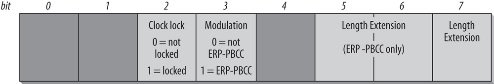
The service field, shown in Figure 14-5, contains control bits to help the receiver decode the frame. As discussed previously, bits 0, 1, and 4 are reserved and must be set to zero. In all 802.11g stations, the transmit and symbol clocks are locked, so bit 2 is always set to 1. Bit 3 is set when the frame body is modulated with PBCC, and set to zero for DSSS, CCK, and DSSS-OFDM modulations. The last three length extension bits are used to assist receivers in determining the frame length in bytes from the Length field, which is expressed in terms of the number of microseconds required for transmission. The standards have a complicated set of rules for when the bits must be set, but they are beyond the level of detail required for this book, especially since the single-carrier framing technique is uncommon.
- Frame Body
The final component of the PLCP frame is its payload, which is the MAC frame, modulated either by PBCC or OFDM. Details of the frame body modulation will be discussed in subsequent sections.


PBCC coding
To transmit a frame using PBCC, the frame data is first run through a convolutional code. The frame is broken into 2-bit elements, and are used as input into a convolutional code that outputs three bits. Each 3-bit block is mapped on to a symbol using 8PSK. Receivers will reverse the process, translating a single phase shift into one of eight symbols. After translating the symbol to a three-bit sequence, the convolutional code is used to remove the redundant bit and recover the original data. See Figure 14-6.
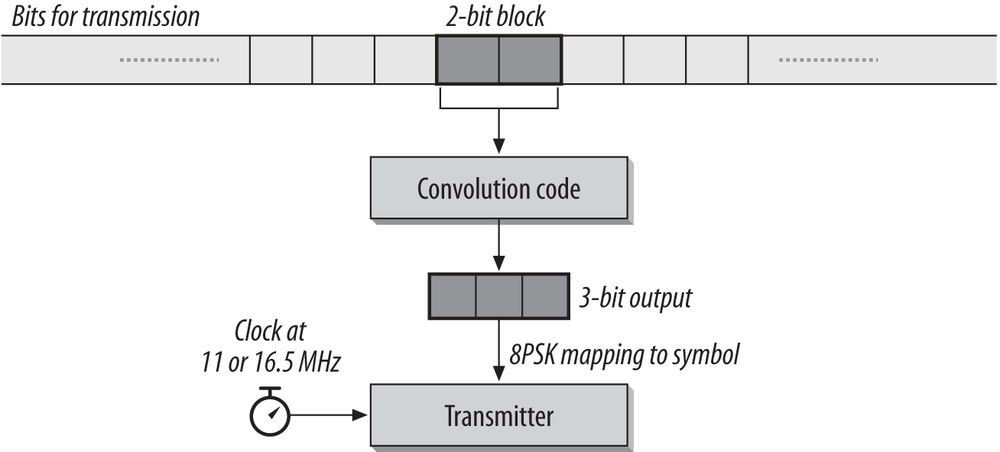
Achieving a 22 Mbps data rate with this physical encoding is straightforward. The symbol clock continues to run at 11 MHz, just as in 802.11b, but each symbol is now capable of transmitting two bits. To run at 33 Mbps, the symbol rate for the data portion of the frame must be increased to 16.5 MHz. At two bits per symbol, the overall data rate is 33 Mbps. Clock speed switching must occur between the PLCP preamble and its payload.
DSSS-OFDM framing
DSSS-OFDM is a hybrid framing technique. The higher-layer packet is encoded with OFDM, and the OFDM-modulated packet is framed with a traditional-single carrier header, as shown in Figure 14-7. Headers are transmitted in accord with 802.11b (including the data scrambler used by 802.11b), but the frame body is modulated using OFDM, in a process identical to the encoding used in 802.11 and described in Chapter 13. Although similar to the encoding in 802.11a, the DSSS-OFDM framing eliminates the initial short training sequences. It also adds a 6 μs signal extension field to allow the convolution decode extra time to finish. The transition from direct sequence modulation to OFDM that occurs at the end of the PLCP header is somewhat complex from a radio engineering point of view, but is beyond the scope of this book.
ERP Physical Medium Dependent (PMD) Layer
Once the PLCP frame is ready for transmission, it is dispatched to the Physical Medium Dependent (PMD) layer. The PMD is responsible for taking the data and sending it out the antenna. Due to the wide variety of modulation schemes that might be used, an 802.11g transceiver must implement several different transmission modes, either wholly or partially, and switch between them as needed. Some functions, however, are shared by all transceivers regardless of operating mode.

Clear Channel Assessment (CCA)
Only one CCA mode is defined for 802.11g, which combines a minimum energy threshold with the ability to decode a signal. Energy detection is based on receiving a valid signal at the start of a transmission slot with a signal power of -76 dBm or greater. As a performance requirement, within a specified window, the PHY should have a high probability of correctly reporting the medium busy. Both the time window and the probability are shown in Table 14-2.
Long slot (20 μs) | Short slot (9 μs) | |
CCA time | 15 μs | 4 μs |
Detection probability | >99% | >90% |
CCA is integrated with a PLCP-level virtual carrier sense. When a PLCP header is received, it will include a length field that indicates the amount of time the medium will be busy. The physical layer will continue to report the medium busy for that time period, even if the physical signal is lost. (Note that this is similar in concept and operation to the Network Allocation Vector at the MAC layer.) Part of the reason for doing this is that not all implementations will support all the transmission modes, so it is important that the physical layer correctly avoids interfering with transmissions it cannot demodulate.
Reception Procedure
802.11g stations have a more complicated procedure for receiving frames than chips that implement other standards because of the choice and backwards compatibility. When an incoming frame is detected, an 802.11g station will need to detect it and then demodulate it with the correct physical layer.
Is the preamble an OFDM preamble (like 802.11a), or the traditional single-carrier preamble used by 802.11b? Frames modulated with OFDM will be processed exactly the same as 802.11a frames, just received on a different frequency.
If the frame is not an OFDM frame, it must decode the preamble, and find the end of the preamble to see the PLCP SIGNAL and SERVICE fields.
By decoding the PLCP header, the appropriate modulation can be employed to demodulate the frame body.
If the SERVICE field indicates that the frame is modulated with PBCC, the PBCC reception procedures will be triggered.
If the SERVICE field doesn’t indicate the presence of PBCC, the data rate is checked. Data rates of 1 and 2 Mbps are processed with the DSSS reception algorithm, and data rates of 5.5 Mbps and 11 Mbps are processed according to the CCK reception algorithm; both are described in Chapter 12.
If the SIGNAL field indicates a speed of 3 Mbps, DSSS-OFDM reception is used. It will switch the demodulator to receiving OFDM at the end of the PLCP header.
Characteristics of the ERP PHY
802.11g has very similar characteristics to 802.11a, with one notable exception. Although each channel has similar performance to an 802.11a channel, there are only three channels. If each channel is run at the highest data rate and 50% efficiency, the total aggregate throughput is only 81 Mbps. It is a high number, but does not begin to approach 802.11a.
Parameter | Value | Notes |
Maximum MAC frame length | 4,095 bytes | |
Slot time | 20 μs 9 μs | If the network consists only of 802.11g stations, the slot time may be shortened from the 802.11b-compatible value to the shorter value used in 802.11a. |
SIFS time | 10 μs | The SIFS is used to derive the value of the other interframe spaces (DIFS, PIFS, and EIFS). |
Signal extension time | 6 μs | Every 802.11g packet is followed by the signal extension time. |
Contention window size | 15 or 31 to 1,023 slots | If the station supports only 802.11b rates, it will be 31 slots for compatibility. Otherwise, the contention window may be shorter. |
Preamble duration | 20 μs |
|
[64] See “When is 54 Not Equal to 54: An Analysis of 802.11g Throughput” at http://www.oreillynet.com/pub/a/wireless/2003/08/08/wireless_throughput.html.