
Chapter 3. 802.11 MAC Fundamentals
This chapter begins our exploration of the 802.11 standard in depth. Chapter 2 provided a high-level overview of the standard and discussed some of its fundamental attributes. You are now at a fork in the book. Straight ahead lies a great deal of information on the 802.11 specification and the various related standards that it uses liberally. It is possible, however, to build a wired network without a thorough and detailed understanding of the protocols, and the same is true for wireless networks. However, there are a number of situations in which you may need a deeper knowledge of the machinery under the hood:
Although 802.11 has been widely and rapidly adopted, security issues have continued to grab headlines. Network managers will undoubtedly be asked to comment on security issues, especially in any wireless LAN proposals. To understand and participate in these discussions, read Chapter 5 and 6. WEP with static keys should be considered fully broken. Solutions based on 802.1X and dynamic WEP keying are significantly stronger, with the full complement of protocols in 802.11i described in Chapter 7 stronger still.
Troubleshooting wireless networks is similar to troubleshooting wired networks but can be much more complex. As always, a trusty packet sniffer can be an invaluable aid. To take full advantage of a packet sniffer, though, you need to understand what the packets mean to interpret your network’s behavior.
Tuning a wireless network is tied intimately to a number of parameters in the specification, as well as the behavior of the underlying radio technology. To understand the behavior of your network and what effect the optimizations will have requires a knowledge of what those parameters really do and how radio waves travel throughout your environment.
Device drivers may expose low-level knobs and dials for you to play with. Most drivers provide good defaults for all of the parameters, but some give you freedom to experiment. Open source software users have the source code and are free to experiment with any and all settings.
Wireless LAN technology is developing rapidly, and new protocol features are constantly being added. A solid understanding of the base protocol allows you to understand how new features will function and what they will mean for your network.
As with many other things in life, the more you know, the better off you are. Ethernet is usually trouble-free, but serious network administrators have long known that when you do run into trouble, there is no substitute for thorough knowledge of how the network is working. When the first edition of this book was out, wireless LANs had been given a “free ride.” Because they were cool, users were forgiving when they failed; wireless connectivity was a privilege, not a right. And since there were relatively few networks and relatively few users on those networks, the networks were rarely subjected to severe stresses. An Ethernet that has only a half dozen nodes is not likely to be a source of problems; problems occur when you add a few high-capacity servers, a few hundred users, and the associated bridges and routers to glue everything together. As the typical 802.11 network grew up from an access point or two serving a dozen users into a much larger network designed to provide seamless coverage throughout a building, the stresses on the equipment and protocols has become much more apparent.
That is why you should read this chapter. Now on to the details. The key to the 802.11 specification is the MAC. It rides on every physical layer and controls the transmission of user data into the air. It provides the core framing operations and the interaction with a wired network backbone. Different physical layers may provide different transmission speeds, all of which are supposed to interoperate.
802.11 does not depart from the previous IEEE 802 standards in any radical way. The standard successfully adapts Ethernet-style networking to radio links. Like Ethernet, 802.11 uses a carrier sense multiple access (CSMA) scheme to control access to the transmission medium. However, collisions waste valuable transmission capacity, so rather than the collision detection (CSMA/CD) employed by Ethernet, 802.11 uses collision avoidance (CSMA/CA). Also like Ethernet, 802.11 uses a distributed access scheme with no centralized controller. Each 802.11 station uses the same method to gain access to the medium. The major differences between 802.11 and Ethernet stem from the differences in the underlying medium.
This chapter provides some insight into the motivations of the MAC designers by describing some challenges they needed to overcome and describes the rules used for access to the medium, as well as the basic frame structure. If you simply want to understand the basic frame sequences that you will see on an 802.11 network, skip ahead to the end of this chapter. For further information on the MAC, consult its formal specification in Clause 9 of the 802.11 standard; detailed MAC state diagrams are in Annex C.
Challenges for the MAC
Differences between the wireless network environment and the traditional wired environment create challenges for network protocol designers. This section examines a number of the hurdles that the 802.11 designers faced.
RF Link Quality
On a wired Ethernet, it is reasonable to transmit a frame and assume that the destination receives it correctly. Radio links are different, especially when the frequencies used are unlicensed ISM bands. Even narrowband transmissions are subject to noise and interference, but unlicensed devices must assume that interference will exist and work around it. The designers of 802.11 considered ways to work around the radiation from microwave ovens and other RF sources. In addition to the noise, multipath fading may also lead to situations in which frames cannot be transmitted because a node moves into a dead spot.
Unlike many other link layer protocols, 802.11 incorporates positive acknowledgments. All transmitted frames must be acknowledged, as shown in Figure 3-1. If any part of the transfer fails, the frame is considered lost.

The sequence in Figure 3-1 is an atomic operation, which means it is a single transactional unit. Although there are multiple steps in the transaction, it is considered a single indivisible operation. Atomic operations are “all or nothing.” Either every step in the sequence must complete successfully, or the entire operation is considered a failure. The sender of the data frame must receive an acknowledgment, or the frame is considered lost. It does not matter from the sender’s perspective whether the initial data frame was lost in transit, or the corresponding acknowledgment was lost in transit. In either case, the data frame must be retransmitted.
One of the additional complexities of treating the frame transmission of Figure 3-1 as atomic is that the transaction occurs in two pieces, subject to control by two different stations. Both stations must work together to jointly take control of the network medium for transmissions during the entire transaction. 802.11 allows stations to lock out contention during atomic operations so that atomic sequences are not interrupted by other stations attempting to use the transmission medium.
Radio link quality also influences the speed at which a network can operate. Good quality signals can carry data at a higher speed. Signal quality degrades with range, which means that the data transmission speed of an 802.11 station depends on its location relative to the access point. Stations must implement a method for determining when to change the data rate in response to changing conditions. Furthermore, the complete collection of stations in a network must manage transmissions at multiple speeds. Rules for multirate support are discussed later in this chapter.
The Hidden Node Problem
In Ethernet networks, stations depend on the reception of transmissions to perform the carrier sensing functions of CSMA/CD. Wires in the physical medium contain the signals and distribute them to network nodes. Wireless networks have fuzzier boundaries, sometimes to the point where each node may not be able to directly communicate with every other node in the wireless network, as in Figure 3-2.
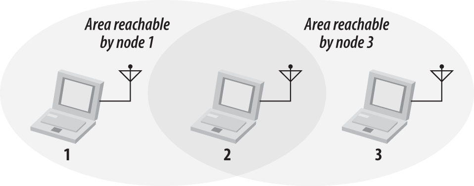
In the Figure 3-2, node 2 can communicate with both nodes 1 and 3, but something prevents nodes 1 and 3 from communicating directly. (The obstacle itself is not relevant; it could be as simple as nodes 1 and 3 being as far away from 2 as possible, so the radio waves cannot reach the full distance from 1 to 3.) From the perspective of node 1, node 3 is a “hidden” node. If a simple transmit-and-pray protocol was used, it would be easy for node 1 and node 3 to transmit simultaneously, thus rendering node 2 unable to make sense of anything. Furthermore, nodes 1 and 3 would not have any indication of the error because the collision was local to node 2.
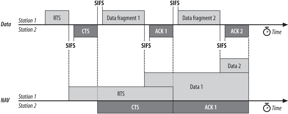
Collisions resulting from hidden nodes may be hard to detect in wireless networks because wireless transceivers are generally half-duplex; they don’t transmit and receive at the same time. To prevent collisions, 802.11 allows stations to use Request to Send (RTS) and Clear to Send (CTS) signals to clear out an area. Both the RTS and CTS frames extend the frame transaction, so that the RTS frame, CTS frame, the data frame, and the final acknowledgment are all considered part of the same atomic operation. Figure 3-3 illustrates the procedure.

In Figure 3-3, node 1 has a frame to send; it initiates the process by sending an RTS frame. The RTS frame serves several purposes: in addition to reserving the radio link for transmission, it silences any stations that hear it. If the target station receives an RTS, it responds with a CTS. Like the RTS frame, the CTS frame silences stations in the immediate vicinity. Once the RTS/CTS exchange is complete, node 1 can transmit its frames without worry of interference from any hidden nodes. Hidden nodes beyond the range of the sending station are silenced by the CTS from the receiver. When the RTS/CTS clearing procedure is used, any frames must be positively acknowledged.
The multiframe RTS/CTS transmission procedure consumes a fair amount of capacity, especially because of the additional latency incurred before transmission can commence. As a result, it is used only in high-capacity environments and environments with significant contention on transmission. For lower-capacity environments, it is not necessary.
Hidden nodes have also become less of a problem as 802.11 has grown up. In small, quiescent networks with only a few stations associated to an access point, there is very little risk of simultaneous transmission, and plenty of spare capacity to be used for retransmission. In many larger environments, the coverage is dense enough that the clients are located physically close enough to an access point that they are all within range of each other. (In fact, the range of many client systems is probably too large for most networks, which will be explored in the planning phase of this book.)
You can control the RTS/CTS procedure by setting the RTS threshold if the device driver for your 802.11 card allows you to adjust it. The RTS/CTS exchange is performed for frames larger than the threshold. Frames shorter than the threshold are simply sent.
MAC Access Modes and Timing
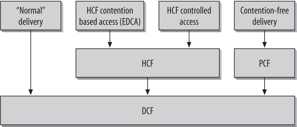
Access to the wireless medium is controlled by coordination functions. Ethernet-like CSMA/CA access is provided by the distributed coordination function (DCF). If contention-free service is required, it can be provided by the point coordination function (PCF), which is built on top of the DCF. Between the free-for-all of the DCF and the precision of the PCF, networks can use the hybrid coordination function (HCF), a middle ground for quality of service between the two extremes. Contention-free services are provided only in infrastructure networks, but quality of service may be provided in any network that has HCF support in the stations. The coordination functions are described in the following list and illustrated in Figure 3-4:
- DCF
The DCF is the basis of the standard CSMA/CA access mechanism. Like Ethernet, it first checks to see that the radio link is clear before transmitting. To avoid collisions, stations use a random backoff after each frame, with the first transmitter seizing the channel. In some circumstances, the DCF may use the CTS/RTS clearing technique to further reduce the possibility of collisions.
- PCF
The point coordination function provides contention-free services. Special stations called point coordinators are used to ensure that the medium is provided without contention. Point coordinators reside in access points, so the PCF is restricted to infrastructure networks. To gain priority over standard contention-based services, the PCF allows stations to transmit frames after a shorter interval. The PCF is not widely implemented and is described in Chapter 9.
- HCF
Some applications need to have service quality that is a step above best-effort delivery, but the rigorous timing of the PCF is not required. The HCF allows stations to maintain multiple service queues and balance access to the wireless medium in favor of applications that require better service quality. The HCF is not fully standardized yet, but is being produced as part of the eventual 802.11e specification.
Adding quality of service to the 802.11 MAC was a significant undertaking. Due to the added complexity in terms of framing, queue management, and signaling, the quality of service specifications were still subject to standards committee wrangling as this book was written, and discussion of them must be postponed to a future edition.
Carrier-Sensing Functions and the Network Allocation Vector
Carrier sensing is used to determine if the medium is available. Two types of carrier-sensing functions in 802.11 manage this process: the physical carrier-sensing and virtual carrier-sensing functions. If either carrier-sensing function indicates that the medium is busy, the MAC reports this to higher layers.
Physical carrier-sensing functions are provided by the physical layer in question and depend on the medium and modulation used. It is difficult (or, more to the point, expensive) to build physical carrier-sensing hardware for RF-based media, because transceivers can transmit and receive simultaneously only if they incorporate expensive electronics. Furthermore, with hidden nodes potentially lurking everywhere, physical carrier-sensing cannot provide all the necessary information.
Virtual carrier-sensing is provided by the Network Allocation Vector (NAV). Most 802.11 frames carry a duration field, which can be used to reserve the medium for a fixed time period. The NAV is a timer that indicates the amount of time the medium will be reserved, in microseconds. Stations set the NAV to the time for which they expect to use the medium, including any frames necessary to complete the current operation. Other stations count down from the NAV to 0. When the NAV is nonzero, the virtual carrier-sensing function indicates that the medium is busy; when the NAV reaches 0, the virtual carrier-sensing function indicates that the medium is idle.
By using the NAV, stations can ensure that atomic operations are not interrupted. For example, the RTS/CTS sequence in Figure 3-3 is atomic. Figure 3-5 shows how the NAV protects the sequence from interruption. (This is a standard format for a number of diagrams in this book that illustrate the interaction of multiple stations with the corresponding timers.) Activity on the medium by stations is represented by the shaded bars, and each bar is labeled with the frame type. Interframe spacing is depicted by the lack of any activity. Finally, the NAV timer is represented by the bars on the NAV line at the bottom of the figure. The NAV is carried in the frame headers on the RTS and CTS frames; it is depicted on its own line to show how the NAV relates to actual transmissions in the air. When a NAV bar is present on the NAV line, stations should defer access to the medium because the virtual carrier-sensing mechanism will indicate a busy medium.
To ensure that the sequence is not interrupted, node 1 sets the NAV in its RTS to block access to the medium while the RTS is being transmitted. All stations that hear the RTS defer access to the medium until the NAV elapses.

RTS frames are not necessarily heard by every station in the network. Therefore, the recipient of the intended transmission responds with a CTS that includes a shorter NAV. This NAV prevents other stations from accessing the medium until the transmission completes. After the sequence completes, the medium can be used by any station after distributed interframe space (DIFS), which is depicted by the contention window beginning at the right side of the figure.
RTS/CTS exchanges may be useful in crowded areas with multiple overlapping networks. Every station on the same physical channel receives the NAV and defers access appropriately, even if the stations are configured to be on different networks.
Interframe Spacing
As with traditional Ethernet, the interframe spacing plays a large role in coordinating access to the transmission medium. 802.11 uses four different interframe spaces. Three are used to determine medium access; the relationship between them is shown in Figure 3-6.
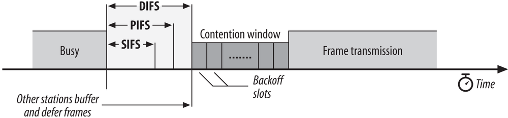
We’ve already seen that as part of the collision avoidance built into the 802.11 MAC, stations delay transmission until the medium becomes idle. Varying interframe spacings create different priority levels for different types of traffic. The logic behind this is simple: high-priority traffic doesn’t have to wait as long after the medium has become idle. Therefore, if there is any high-priority traffic waiting, it grabs the network before low-priority frames have a chance to try. To assist with interoperability between different data rates, the interframe space is a fixed amount of time, independent of the transmission speed. (This is only one of the many problems caused by having different physical layers use the same radio resources, which are different modulation techniques.) Different physical layers, however, can specify different interframe space times.
- Short interframe space (SIFS)
The SIFS is used for the highest-priority transmissions, such as RTS/CTS frames and positive acknowledgments. High-priority transmissions can begin once the SIFS has elapsed. Once these high-priority transmissions begin, the medium becomes busy, so frames transmitted after the SIFS has elapsed have priority over frames that can be transmitted only after longer intervals.
- PCF interframe space (PIFS)
The PIFS, sometimes erroneously called the priority interframe space, is used by the PCF during contention-free operation. Stations with data to transmit in the contention-free period can transmit after the PIFS has elapsed and preempt any contention-based traffic.
- DCF interframe space (DIFS)
The DIFS is the minimum medium idle time for contention-based services. Stations may have immediate access to the medium if it has been free for a period longer than the DIFS.
- Extended interframe space (EIFS)
The EIFS is not illustrated in Figure 3-6 because it is not a fixed interval. It is used only when there is an error in frame transmission.
Interframe spacing and priority
Atomic operations start like regular transmissions: they must wait for the the relevant interframe space, typically the DIFS, to end before they can begin. However, the second and any subsequent steps in an atomic operation take place after the SIFS, rather than after the DIFS. Because the SIFS is shorter than the other interframe spaces, the second (and subsequent) parts of an atomic operation will grab the medium before another type of frame can be transmitted. By using the SIFS and the NAV, stations can seize the medium for as long as necessary.
In Figure 3-5, for example, the short interframe space is used between the different units of the atomic exchange. After the sender gains access to the medium, the receiver replies with a CTS after the SIFS. Any stations that might attempt to access the medium at the conclusion of the RTS would wait for one DIFS interval. Partway through the DIFS interval, though, the SIFS interval elapses, and the CTS is transmitted.
Contention-Based Access Using the DCF
Most traffic uses the DCF, which provides a standard Ethernet-like contention-based service. The DCF allows multiple independent stations to interact without central control, and thus may be used in either IBSS networks or in infrastructure networks.
Before attempting to transmit, each station checks whether the medium is idle. If the medium is not idle, stations defer to each other and employ an orderly exponential backoff algorithm to avoid collisions.
In distilling the 802.11 MAC rules, there is a basic set of rules that are always used, and additional rules may be applied depending on the circumstances. Two basic rules apply to all transmissions using the DCF:
If the medium has been idle for longer than the DIFS, transmission can begin immediately. Carrier sensing is performed using both a physical medium-dependent method and the virtual (NAV) method.
If the previous frame was received without errors, the medium must be free for at least the DIFS.
If the previous transmission contained errors, the medium must be free for the amount of the EIFS.
If the medium is busy, the station must wait for the channel to become idle. 802.11 refers to the wait as access deferral. If access is deferred, the station waits for the medium to be idle for the DIFS and prepares for the exponential backoff procedure.
Additional rules may apply in certain situations. Many of these rules depend on the particular situation “on the wire” and are specific to the results of previous transmissions.
Error recovery is the responsibility of the station sending a frame. Senders expect acknowledgments for each transmitted frame and are responsible for retrying the transmission until it is successful.
Positive acknowledgments are the only indication of success. Atomic exchanges must complete in their entirety to be successful. If an acknowledgment is expected and does not arrive, the sender considers the transmission lost and must retry.
All unicast data must be acknowledged. Broadcast data is not acknowledged. (As a result, unicast data has an inherently higher service quality than broadcast data, even though the radio link is inherently a broadcast medium.)
Any failure increments a retry counter, and the transmission is retried. A failure can be due to a failure to gain access to the medium or a lack of an acknowledgment. However, there is a longer contention window when transmissions are retried (see next section).
Multiframe sequences may update the NAV with each step in the transmission procedure. When a station receives a medium reservation that is longer than the current NAV, it updates the NAV. Setting the NAV is done on a frame-by-frame basis and is discussed in much more detail in the next chapter.
The following types of frames can be transmitted after the SIFS and thus receive maximum priority: acknowledgments, the CTS in an RTS/CTS exchange sequence, and fragments in fragment sequences.
Once a station has transmitted the first frame in a sequence, it has gained control of the channel. Any additional frames and their acknowledgments can be sent using the short interframe space, which locks out any other stations.
Additional frames in the sequence update the NAV for the expected additional time the medium will be used.
Extended frame sequences are required for higher-level packets that are larger than configured thresholds.
Packets larger than the RTS threshold must have RTS/CTS exchange.
Packets larger than the fragmentation threshold must be fragmented.
Error Recovery with the DCF
Error detection and correction is up to the station that begins an atomic frame exchange. When an error is detected, the station with data must resend the frame. Errors must be detected by the sending station. In some cases, the sender can infer frame loss by the lack of a positive acknowledgment from the receiver. Retry counters are incremented when frames are retransmitted.
Each frame or fragment has a single retry counter associated with it. Stations have two retry counters: the short retry count and the long retry count. Frames that are shorter than the RTS threshold are considered to be short; frames longer than the threshold are long. Depending on the length of the frame, it is associated with either a short or long retry counter. Frame retry counts begin at 0 and are incremented when a frame transmission fails.
The short retry count is reset to 0 when:
A CTS frame is received in response to a transmitted RTS
A MAC-layer acknowledgment is received after a nonfragmented transmission
A broadcast or multicast frame is received
The long retry count is reset to 0 when:
A MAC-layer acknowledgment is received for a frame longer than the RTS threshold
A broadcast or multicast frame is received
In addition to the associated retry count, fragments are given a maximum “lifetime” by the MAC. When the first fragment is transmitted, the lifetime counter is started. When the lifetime limit is reached, the frame is discarded and no attempt is made to transmit any remaining fragments. Naturally, higher-layer protocols may detect any loss and retransmit the data; when a higher-level protocol such as TCP retransmits data, though, it would be a new frame to the 802.11 MAC and all the retry counters will be restarted.
Using the retry counters
Like most other network protocols, 802.11 provides reliability through retransmission. Data transmission happens within the confines of an atomic sequence, and the entire sequence must complete for a transmission to be successful. When a station transmits a frame, it must receive an acknowledgment from the receiver or it will consider the transmission to have failed. Failed transmissions increment the retry counter associated with the frame (or fragment). If the retry limit is reached, the frame is discarded, and its loss is reported to higher-layer protocols.
One of the reasons for having short frames and long frames is to allow network administrators to customize the robustness of the network for different frame lengths. Large frames require more buffer space, so one potential application of having two separate retry limits is to decrease the long retry limit to decrease the amount of buffer space required.
Backoff with the DCF
After frame transmission has completed and the DIFS has elapsed, stations may attempt to transmit congestion-based data. A period called the contention window or backoff window follows the DIFS. This window is divided into slots. Slot length is medium-dependent; higher-speed physical layers use shorter slot times. Stations pick a random slot and wait for that slot before attempting to access the medium; all slots are equally likely selections. When several stations are attempting to transmit, the station that picks the first slot (the station with the lowest random number) wins. According to the standard, all slot numbers should be equally likely; see the sidebar on Spectralink Voice Priority later in this chapter for one notable exception.
As in Ethernet, the backoff time is selected from a larger range each time a transmission fails. Figure 3-7 illustrates the growth of the contention window as the number of transmissions increases, using the numbers from the 802.11b direct-sequence spread-spectrum (DSSS) physical layer. Other physical layers use different sizes, but the principle is identical. Contention window sizes are always 1 less than a power of 2 (e.g., 31, 63, 127, 255). Each time the retry counter increases, the contention window moves to the next greatest power of two. The size of the contention window is limited by the physical layer. For example, the DS physical layer limits the contention window to 1,023 transmission slots.
When the contention window reaches its maximum size, it remains there until it can be reset. Allowing long contention windows when several competing stations are attempting to gain access to the medium keeps the MAC algorithms stable even under maximum load. The contention window is reset to its minimum size when frames are transmitted successfully, or the associated retry counter is reached, and the frame is discarded.

Fragmentation and Reassembly
Higher-level packets and some large management frames may need to be broken into smaller pieces to fit through the wireless channel. Fragmentation may also help improve reliability in the presence of interference. Wireless LAN stations may attempt to fragment transmissions so that interference affects only small fragments, not large frames. By immediately reducing the amount of data that can be corrupted by interference, fragmentation may result in a higher effective throughput. Interference may come from a variety of sources. Some, but by no means all, microwave ovens cause interference with 2.4 GHz networks.[13] Electromagnetic radiation is generated by the magnetron tube during its ramp-up and ramp-down, so microwaves emit interference half the time. Many newer cordless phones also cause interference.[14] Outdoor networks are subject to a much wider variety of interference.
Fragmentation takes place when the length of a higher-level packet exceeds the fragmentation threshold configured by the network administrator. Fragments all have the same frame sequence number but have ascending fragment numbers to aid in reassembly. Frame control information also indicates whether more fragments are coming. All of the fragments that comprise a frame are normally sent in a fragmentation burst, which is shown in Figure 3-8. This figure also incorporates an RTS/CTS exchange, because it is common for the fragmentation and RTS/CTS thresholds to be set to the same value. The figure also shows how the NAV and SIFS are used in combination to control access to the medium.

Fragments and their acknowledgments are separated by the SIFS, so a station retains control of the channel during a fragmentation burst. The NAV is also used to ensure that other stations do not use the channel during the fragmentation burst. As with any RTS/CTS exchange, the RTS and CTS both set the NAV from the expected time to the end of the first fragments in the air. Subsequent fragments then form a chain. Each fragment sets the NAV to hold the medium until the end of the acknowledgment for the next frame. Fragment 0 sets the NAV to hold the medium until ACK 1, fragment 1 sets the NAV to hold the medium until ACK 2, and so on. After the last fragment and its acknowledgment have been sent, the NAV is set to 0, indicating that the medium will be released after the fragmentation burst completes.
Frame Format
To meet the challenges posed by a wireless data link, the MAC was forced to adopt several unique features, not the least of which was the use of four address fields. Not all frames use all the address fields, and the values assigned to the address fields may change depending on the type of MAC frame being transmitted. Details on the use of address fields in different frame types are presented in Chapter 4. Figure 3-9 shows the generic 802.11 MAC frame. All diagrams in this section follow the IEEE conventions in 802.11. Fields are transmitted from left to right.

802.11 MAC frames do not include some of the classic Ethernet frame features, most notably the type/length field and the preamble. The preamble is part of the physical layer, and encapsulation details such as type and length are present in the header on the data carried in the 802.11 frame.
Frame Control
Each frame starts with a two-byte Frame Control subfield, shown in Figure 3-10. The components of the Frame Control subfield are:
- Protocol version
Two bits indicate which version of the 802.11 MAC is contained in the rest of the frame. At present, only one version of the 802.11 MAC has been developed; it is assigned the protocol number 0. Other values will appear when the IEEE standardizes changes to the MAC that render it incompatible with the initial specification. So far, none of the revisions to 802.11 have required incrementing the protocol number.
- Type and subtype fields
Type and subtype fields identify the type of frame used. To cope with noise and unreliability, a number of management functions are incorporated into the 802.11 MAC. Some, such as the RTS/CTS operations and the acknowledgments, have already been discussed. Table 3-1 shows how the type and subtype identifiers are used to create the different classes of frames.

In Table 3-1, bit strings are written most-significant bit first, which is the reverse of the order used in Figure 3-10. Therefore, the frame type is the third bit in the frame control field followed by the second bit (b3 b2), and the subtype is the seventh bit, followed by the sixth, fifth, and fourth bits (b7 b6 b5 b4).
Subtype value | Subtype name |
Management frames (type=00)[a] | |
0000 | Association request |
0001 | Association response |
0010 | Reassociation request |
0011 | Reassociation response |
0100 | Probe request |
0101 | Probe response |
1000 | Beacon |
1001 | Announcement traffic indication message (ATIM) |
1010 | Disassociation |
1011 | Authentication |
1100 | Deauthentication |
1101 | Action (for spectrum management with 802.11h, also for QoS) |
Control frames (type=01)[b] | |
1000 | Block Acknowledgment Request (QoS) |
1001 | Block Acknowledgment (QoS) |
1010 | Power Save (PS)-Poll |
1011 | RTS |
1100 | CTS |
1101 | Acknowledgment (ACK) |
1110 | Contention-Free (CF)-End |
1111 | CF-End+CF-Ack |
Data frames (type=10) | |
0000 | Data |
0001 | Data+CF-Ack |
0010 | Data+CF-Poll |
0011 | Data+CF-Ack+CF-Poll |
0100 | Null data (no data transmitted) |
0101 | CF-Ack (no data transmitted) |
0110 | CF-Poll (no data transmitted) |
0111 | CF-Ack+CF-Poll (no data transmitted) |
1000 | QoS Data[c] |
1001 | QoS Data + CF-Ack[c] |
1010 | QoS Data + CF-Poll[c] |
1011 | QoS Data + CF-Ack + CF-Poll[c] |
1100 | QoS Null (no data transmitted)[c] |
1101 | QoS CF-Ack (no data transmitted)[c] |
1110 | QoS CF-Poll (no data transmitted)[c] |
1111 | QoS CF-Ack+CF-Poll (no data transmitted)[c] |
(Frame type 11 is reserved) | |
[a] Management subtypes 0110-0111 and 1110-1111 are reserved and not currently used. [b] Control subtypes 0000-0111 are reserved and not currently used. [c] Proposed by the 802.11e task group, but not yet standardized. Note that these frames all have a leading one, which has caused some to refer to the first bit as the QoS bit. | |
- ToDS and FromDS bits
These bits indicate whether a frame is destined for the distribution system. All frames on infrastructure networks will have one of the distribution system bits set. Table 3-2 shows how these bits are interpreted. As Chapter 4 will explain, the interpretation of the address fields depends on the setting of these bits.
Table 3-2. Interpreting the ToDS and FromDS bitsTo DS=0
To DS=1
From DS=0
All management and control frames Data frames within an IBSS (never infrastructure data frames)
Data frames transmitted from a wireless station in an infrastructure network.
From DS=1
Data frames received for a wireless station in an infrastructure network
Data frames on a “wireless bridge”
- More fragments bit
This bit functions much like the “more fragments” bit in IP. When a higher-level packet has been fragmented by the MAC, the initial fragment and any following nonfinal fragments set this bit to 1. Large data frames and some management frames may be large enough to require fragmentation; all other frames set this bit to 0. In practice, most data frames are transmitted at the maximum Ethernet size and fragmentation is not often used.
- Retry bit
From time to time, frames may be retransmitted. Any retransmitted frames set this bit to 1 to aid the receiving station in eliminating duplicate frames.
- Power management bit
Network adapters built on 802.11 are often built to the PC Card form factor and used in battery-powered laptop or handheld computers. To conserve battery life, many small devices have the ability to power down parts of the network interface. This bit indicates whether the sender will be in a powersaving mode after the completion of the current atomic frame exchange. 1 indicates that the station will be in powersave mode, and 0 indicates that the station will be active. Access points perform a number of important management functions and are not allowed to save power, so this bit is always 0 in frames transmitted by an access point.
- More data bit
To accommodate stations in a powersaving mode, access points may buffer frames received from the distribution system. An access point sets this bit to indicate that at least one frame is available and is addressed to a dozing station.
- Protected Frame bit
Wireless transmissions are inherently easier to intercept than transmissions on a fixed network. If the frame is protected by link layer security protocols, this bit is set to 1, and the frame changes slightly. The Protected Frame bit was previously called the WEP bit.
- Order bit
Frames and fragments can be transmitted in order at the cost of additional processing by both the sending and receiving MACs. When the “strict ordering” delivery is employed, this bit is set to 1.
Duration/ID Field
The Duration/ID field follows the frame control field. This field has several uses and takes one of the three forms shown in Figure 3-11.

Duration: setting the NAV
When bit 15 is 0, the duration/ID field is used to set the NAV. The value represents the number of microseconds that the medium is expected to remain busy for the transmission currently in progress. All stations must monitor the headers of all frames they receive and update the NAV accordingly. Any value that extends the amount of time the medium is busy updates the NAV and blocks access to the medium for additional time.
Frames transmitted during contention-free periods
During the contention-free periods, bit 14 is 0 and bit 15 is 1. All other bits are 0, so the duration/ID field takes a value of 32,768. This value is interpreted as a NAV. It allows any stations that did not receive the Beacon[15] announcing the contention-free period to update the NAV with a suitably large value to avoid interfering with contention-free transmissions.
PS-Poll frames
Bits 14 and 15 are both set to 1 in PS-Poll frames. Mobile stations may elect to save battery power by turning off antennas. Dozing stations must wake up periodically. To ensure that no frames are lost, stations awaking from their slumber transmit a PS-Poll frame to retrieve any buffered frames from the access point. Along with this request, waking stations incorporate the association ID (AID) that indicates which BSS they belong to. The AID is included in the PS-Poll frame and may range from 1-2,007. Values from 2,008-16,383 are reserved and not used.
Address Fields
An 802.11 frame may contain up to four address fields. The address fields are numbered because different fields are used for different purposes depending on the frame type (details are found in Chapter 4). The general rule of thumb is that Address 1 is used for the receiver, Address 2 for the transmitter, and Address 3 field for filtering by the receiver. In an infrastructure network, for example, the third address field is used by the receiver to determine whether the frame is part of the network it is associated to.[16]
Addressing in 802.11 follows the conventions used for the other IEEE 802 networks, including Ethernet. Addresses are 48 bits long. If the first bit sent to the physical medium is a 0, the address represents a single station (unicast). When the first bit is a 1, the address represents a group of physical stations and is called a multicast (or group) address. If all bits are 1s, then the frame is a broadcast and is delivered to all stations connected to the wireless medium.
48-bit addresses are used for a variety of purposes:
- Destination address
As in Ethernet, the destination address is the 48-bit IEEE MAC identifier that corresponds to the final recipient: the station that will hand the frame to higher protocol layers for processing.
- Source address
This is the 48-bit IEEE MAC identifier that identifies the source of the transmission. Only one station can be the source of a frame, so the Individual/Group bit is always 0 to indicate an individual station.
- Receiver address
This is a 48-bit IEEE MAC identifier that indicates which wireless station should process the frame. If it is a wireless station, the receiver address is the destination address. For frames destined to a node on an Ethernet connected to an access point, the receiver is the wireless interface in the access point, and the destination address may be a router attached to the Ethernet.
- Transmitter address
This is a 48-bit IEEE MAC address to identify the wireless interface that transmitted the frame onto the wireless medium. The transmitter address is used only in wireless bridging.
- Basic Service Set ID (BSSID)
To identify different wireless LANs in the same area, stations may be assigned to a BSS. In infrastructure networks, the BSSID is the MAC address used by the wireless interface in the access point. Ad hoc networks generate a random BSSID with the Universal/Local bit set to 1 to prevent conflicts with officially assigned MAC addresses.
The number of address fields used depends on the type of frame. Most data frames use three fields for source, destination, and BSSID. The number and arrangement of address fields in a data frame depends on how the frame is traveling relative to the distribution system. Most transmissions use three addresses, which is why only three of the four addresses are contiguous in the frame format.
Sequence Control Field
This 16-bit field is used for both defragmentation and discarding duplicate frames. It is composed of a 4-bit fragment number field and a 12-bit sequence number field, as shown in Figure 3-12. Sequence numbers are not used in control frames, so the Sequence Control field is not present.

Higher-level frames are each given a sequence number as they are passed to the MAC for transmission. The sequence number subfield operates as a modulo-4096 counter of the frames transmitted. It begins at 0 and increments by 1 for each higher-level packet handled by the MAC. If higher-level packets are fragmented, all fragments will have the same sequence number. When frames are retransmitted, the sequence number is not changed.
What differs between fragments is the fragment number. The first fragment is given a fragment number of 0. Each successive fragment increments the fragment number by 1. Retransmitted fragments keep their original sequence numbers to assist in reassembly.
Stations that implement the QoS extensions use a slightly different interpretation of the sequence control field because multiple transmit queues need to be maintained.
Frame Body
The frame body, also called the Data field, moves the higher-layer payload from station to station. As originally specified, 802.11 can transmit frames with a maximum payload of 2,304 bytes of higher-level data. Implementations must support larger frame bodies to accommodate additional headers for security and QoS. 802.2 LLC headers use 8 bytes for a maximum network protocol payload of 2,296 bytes. Preventing fragmentation must be done at the protocol layer. On IP networks, Path MTU Discovery (RFC 1191) will prevent the transmission of frames with Data fields larger than 1,500 bytes.
802.11 differs from other link layer technologies in two notable ways. First, there is no higher-level protocol tag in the 802.11 frame to distinguish between higher-layer protocol types. Higher-level protocols are tagged with a type field by an additional header, which is used as the start of the 802.11 payload. Second, 802.11 does not generally pad frames to a minimum length. Many frames used by 802.11 are short, and the chips and electronics used in network interfaces has progressed to the point where a pad is no longer necessary.
Frame Check Sequence
As with Ethernet, the 802.11 frame closes with a frame check sequence (FCS). The FCS is often referred to as the cyclic redundancy check (CRC) because of the underlying mathematical operations. The FCS allows stations to check the integrity of received frames. All fields in the MAC header and the body of the frame are included in the FCS. Although 802.3 and 802.11 use the same method to calculate the FCS, the MAC header used in 802.11 is different from the header used in 802.3, so the FCS must be recalculated by access points.
When frames are sent to the wireless interface, the FCS is calculated before those frames are sent out over the wireless link. Receivers can then calculate the FCS from the received frame and compare it to the received FCS. If the two match, there is a high probability that the frame was not damaged in transit.
On Ethernets, frames with a bad FCS are simply discarded, and frames with a good FCS are passed up the protocol stack. On 802.11 networks, frames that pass the integrity check may also require the receiver to send an acknowledgment. For example, data frames that are received correctly must be positively acknowledged, or they are retransmitted. 802.11 does not have a negative acknowledgment for frames that fail the FCS; stations must wait for the acknowledgment timeout before retransmitting.
Encapsulation of Higher-Layer Protocols Within 802.11
Like all other 802 link layers, 802.11 can transport any network-layer protocol. Unlike Ethernet, 802.11 relies on 802.2 logical-link control (LLC) encapsulation to carry higher-level protocols. Figure 3-13 shows how 802.2 LLC encapsulation is used to carry an IP packet. In the figure, the “MAC headers” for 802.1H and RFC 1042 might be the 12 bytes of source and destination MAC address information on Ethernet or the long 802.11 MAC header from the previous section.

Two different methods can be used to encapsulate LLC data for transmission. One is described in RFC 1042, and the other in 802.1H. Both standards may go by other names. RFC 1042 is sometimes referred to as IETF encapsulation, while 802.1H is sometimes called tunnel encapsulation.
As you can see in Figure 3-13, though, the two methods are quite similar. An Ethernet frame is shown in the top line of Figure 3-13. It has a MAC header composed of source and destination MAC addresses, a type code, the embedded packet, and a frame check field. In the IP world, the Type code is either 0x0800 (2048 decimal) for IP itself, or 0x0806 (2054 decimal) for the Address Resolution Protocol (ARP).
Both RFC 1042 and 802.1H are derivatives of 802.2’s sub-network access protocol (SNAP). The MAC addresses are copied into the beginning of the encapsulation frame, and then a SNAP header is inserted. SNAP headers begin with a destination service access point (DSAP) and a source service access point (SSAP). After the addresses, SNAP includes a Control header. Like high-level data link control (HDLC) and its progeny, the Control field is set to 0x03 to denote unnumbered information (UI), a category that maps well to the best-effort delivery of IP datagrams. The last field inserted by SNAP is an organizationally unique identifier (OUI). Initially, the IEEE hoped that the 1-byte service access points would be adequate to handle the number of network protocols, but this proved to be an overly optimistic assessment of the state of the world. As a result, SNAP copies the type code from the original Ethernet frame. The only difference between 802.1H and RFC 1042 is the OUI used.
At one point, many products offered the option to switch between the two encapsulation standards, though this option is much less common. Microsoft operating systems default to using 802.1H for the AppleTalk protocol suite and IPX, and use RFC 1042 for all other protocols. Most access points now conform to the Microsoft behavior, and no longer have an option to switch encapsulation type. In fact, the Microsoft encapsulation selection is so widely supported that it was part of the Wi-Fi Alliance’s certification test suite at one point.
Contention-Based Data Service
The additional features incorporated into 802.11 to add reliability lead to a confusing tangle of rules about which types of frames are permitted at any point. They also make it more difficult for network administrators to know which frame exchanges they can expect to see on networks. This section clarifies the atomic exchanges that move data on an 802.11 LAN. (Most management frames are announcements to interested parties in the area and transfer information in only one direction.)
The exchanges presented in this section are atomic, which means that they should be viewed as a single unit. Two distinct sets of atomic exchanges are defined by 802.11. One is used by the DCF for contention-based service; those exchanges are described in this chapter. A second set of exchanges is specified for use with the PCF for contention-free services. Frame exchanges used with contention-free services are intricate and harder to understand. Since very few (if any) commercial products implement contention-free service, these exchanges are not described.
Frame exchanges under the DCF dominate the 802.11 MAC. According to the rules of the DCF, all products are required to provide best-effort delivery. To implement the contention-based MAC, stations process MAC headers for every frame while they are active. Exchanges begin with a station seizing an idle medium after the DIFS.
Broadcast and Multicast Data or Management Frames
Broadcast and multicast frames, which can also be referred to as group frames because they are destined for more than one receiving station, have the simplest frame exchanges because there is no acknowledgment. Framing and addressing are somewhat more complex in 802.11, so the types of frames that match this rule are the following:
Broadcast data frames with a broadcast address in the Address 1 field
Multicast data frames with a multicast address in the Address 1 field
Broadcast management frames with a broadcast address in the Address 1 field (Beacon, Probe Request, and IBSS ATIM frames)
Frames destined for group addresses cannot be fragmented and are not acknowledged. The entire atomic sequence is a single frame, sent according to the rules of the contention-based access control. After the previous transmission concludes, all stations wait for the DIFS and begin counting down the random delay intervals in the contention window.
Because the frame exchange is a single-frame sequence, the NAV is set to 0. With no further frames to follow, there is no need to use the virtual carrier-sense mechanism to lock other stations out of using the medium. After the frame is transmitted, all stations wait through the DIFS and begin counting down through the contention window for any deferred frames. See Figure 3-14.

Depending on the environment, frames sent to group addresses may have lower service quality because the frames are not acknowledged. Some stations may therefore miss broadcast or multicast traffic, but there is no facility built into the MAC for retransmitting broadcast or multicast frames.
Unicast Frames
Frames that are destined for a single station are called directed data by the 802.11 standard. This book uses the more common term unicast. Unicast frames must be acknowledged to ensure reliability, which means that a variety of mechanisms can be used to improve efficiency. All the sequences in this section apply to any unicast frame and thus can apply to management frames and data frames. In practice, these operations are usually observed only with data frames.
Basic positive acknowledgment (final fragment)
Reliable transmission between two stations is based on simple positive acknowledgments. Unicast data frames must be acknowledged, or the frame is assumed to be lost. The most basic case is a single frame and its accompanying acknowledgment, as shown in Figure 3-15.

The frame uses the NAV to reserve the medium for the frame, its acknowledgment, and the intervening SIFS. By setting a long NAV, the sender locks the virtual carrier for the entire sequence, guaranteeing that the recipient of the frame can send the acknowledgment. Because the sequence concludes with the ACK, no further virtual carrier locking is necessary, and the NAV in the ACK is set to 0.
Fragmentation
Many higher-layer network protocols, including IP, incorporate fragmentation. The disadvantage of network-layer fragmentation is that reassembly is performed by the final destination; if any of the fragments are lost, the entire packet must be retransmitted. Link layers may incorporate fragmentation to boost speed over a single hop with a small MTU.[17] 802.11 can also use fragmentation to help avoid interference. Radio interference is often in the form of short, high-energy bursts and is frequently synchronized with the AC power line. Breaking a large frame into small frames allows a larger percentage of the frames to arrive undamaged. The basic fragmentation scheme is shown in Figure 3-16.

The last two frames exchanged are the same as in the previous sequence, and the NAV is set identically. However, all frames prior to the penultimate frame use the NAV to lock the medium for the next frame. The first data frame sets the NAV for a long enough period to accommodate its ACK, the next fragment, and the acknowledgment following the next fragment. To indicate that it is a fragment, the MAC sets the More Fragments bit in the frame control field to 1. All nonfinal ACKs continue to extend the lock for the next data fragment and its ACK. Subsequent data frames then continue to lengthen the NAV to include successive acknowledgments until the final data frame, which sets the More Fragments bit to 0, and the final ACK, which sets the NAV to 0. No limit is placed on the number of fragments, but the total frame length must be shorter than any constraint placed on the exchange by the PHY.
Fragmentation is controlled by the fragmentation threshold parameter in the MAC. Most network card drivers allow you to configure this parameter. Any frames larger than the fragmentation threshold are fragmented in an implementation-dependent way. Network administrators can change the fragmentation threshold to tune network behavior. Higher fragmentation thresholds mean that frames are delivered with less overhead, but the cost to a lost or damaged frame is much higher because more data must be discarded and retransmitted. Low fragmentation thresholds have much higher overhead, but they offer increased robustness in the face of hostile conditions.
RTS/CTS
To guarantee reservation of the medium and uninterrupted data transmission, a station can use the RTS/CTS exchange. Figure 3-17 shows this process. The RTS/CTS exchange acts exactly like the initial exchange in the fragmentation case, except that the RTS frame does not carry data. The NAV in the RTS allows the CTS to complete, and the CTS is used to reserve access for the data frame.
RTS/CTS can be used for all frame exchanges, none of them, or something in between. Like fragmentation, RTS/CTS behavior is controlled by a threshold set in the driver software. Frames larger than the threshold are preceded by an RTS/CTS exchange to clear the medium, while smaller frames are simply transmitted.

RTS/CTS with fragmentation
In practice, the RTS/CTS exchange is often combined with fragmentation (Figure 3-18). Fragmented frames are usually quite long and thus benefit from the use of the RTS/CTS procedure to ensure exclusive access to the medium, free from contention from hidden nodes. Some vendors set the default fragmentation threshold to be identical to the default RTS/CTS threshold.
Powersaving Sequences
The most power-hungry components in RF systems are the amplifiers used to boost a signal immediately prior to transmission and to boost the received signal to an intelligible level immediately after its reception. 802.11 stations can maximize battery life by shutting down the radio transceiver and sleeping periodically. During sleeping periods, access points buffer any unicast frames for sleeping stations. These frames are announced by subsequent Beacon frames. To retrieve buffered frames, newly awakened stations use PS-Poll frames.
An access point that receives a PS-Poll frame may respond with the requested data immediately, or at its leisure when circumstances permit. In some cases, the PS-Poll response is determined by the 802.11 chipset vendor in the AP. Some chipset vendors support both modes, while others support only one. 802.11 only requires that one method be supported; both approaches are equally standards-compliant.
Immediate response
Access points can respond immediately to the PS-Poll. After a short interframe space, an access point may transmit the frame. Figure 3-19 shows an implied NAV as a result of the PS-Poll frame. The PS-Poll frame contains an Association ID in the Duration/ID field so that the access point can determine which frames were buffered for the mobile station. However, the MAC specification requires all stations receiving a PS-Poll to update the NAV with an implied value equal to a short interframe space and one ACK. Although the NAV is too short for the data frame, the access point acquires that the medium and all stations defer access for the entire data frame. At the conclusion of the data frame, the NAV is updated to reflect the value in the header of the data frame.

If the buffered frame is large, it may require fragmentation. Figure 3-20 illustrates an immediate PS-Poll response requiring fragmentation. Like all other stations, access points typically have a configurable fragmentation threshold.

Deferred response
Instead of an immediate response, access points can also respond with a simple acknowledgment. This is called a deferred response because the access point acknowledges the request for the buffered frame but does not act on it immediately. One of the advantages of using deferred response is that the software on the access point is somewhat easier to implement because the acknowledgment can be
transmitted immediately by the chipset firmware, and the buffered data may be queued for transmission normally.
A station requesting a frame with a PS-Poll must stay awake until it is delivered. Under contention-based service, however, the access point can deliver a frame at any point. A station cannot return to a low-power mode until it receives a Beacon frame in which its bit in the traffic indication map (TIM) is clear.
Figure 3-21 illustrates this process. In this figure, the station has recently changed from a low-power mode to an active mode, and it notes that the access point has buffered frames for it. It transmits a PS-Poll to the access point to retrieve the buffered frames. However, the access point may choose to defer its response by transmitting only an ACK. At this point, the access point has acknowledged the station’s request for buffered frames and promised to deliver them at some point in the future. The station must wait in active mode, perhaps through several atomic frame exchanges, before the access point delivers the data. A buffered frame may be subject to fragmentation, although Figure 3-21 does not illustrate this case.
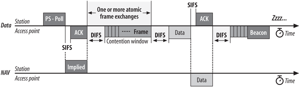
After receiving a data frame, the station must remain awake until the next Beacon is transmitted. Beacon frames only note whether frames are buffered for a station and have no way of indicating the number of frames. Once the station receives a Beacon frame indicating that no more traffic is buffered, it can conclude that it has received the last buffered frame and return to a low-power mode.
Multirate Support
Network technologies that operate at a variety of different speeds must have a method of negotiating a mutually acceptable data rate. Stations may also change speed frequently in response to rapid changes in the radio environment. As the distance between stations varies, the speed will vary as well. Stations must adapt to the changing environment by altering transmission speed as necessary. As with many other protocol features, the 802.11 standards do not specify how a rate is selected. General rules are laid down by the standard, and vendors have a great deal of freedom in implementing the details. There are a few general rules that are required of all stations:
Every station maintains a list of operational rates, which is the list of rates that are supported by both the station and the BSS serving it. (A BSS typically corresponds to an access point, but newer products may offer the ability to customize operational rates on a “virtual AP” basis.) No frames may be transmitted at a rate that is higher than any rate in the operational rate set.
Every BSS must also maintain a basic rate set, which is a list of data rates that must be supported by every station joining the BSS. Any frame sent to a group receiver address must be transmitted at a basic rate, ensuring that all stations can demodulate it correctly.
Control frames that start a frame exchange, such as RTS and CTS frames, must also be transmitted at one of the rates in the basic rate set. This rule ensures that a station which must transmit a CTS frame in response to an RTS frame can do so at the same rate.
— Control frames may be used in a backwards-compatiblity mode called protection (see Chapter 14). Protection mode is intended to prevent interference between a station supporting only an older, slower radio modulation and a newer station that supports faster radio modulations. Protection frames must be transmitted using older modulations if there are stations incapable of using newer modulations in the area.
Frames destined for a single station will have a unicast destination address in the Address 1 field of the frame. Unicast frames can be transmitted at any rate which is known to be supported by the destination. Selection of the data rate is not specified by any 802.11 standard.
— Frames used in the contention-free period (see Chapter 9) may serve multiple purposes. If a frame includes an ACK, it is intended for the previous transmitter rather than the frame recipient. The transmitter must ensure that the frame is transmitted at a rate supported by both the receiver and the station the ACK is intended for.
Response frames, such as acknowledgments or CTS frames, must be transmitted at a rate in the basic rate set, but no faster than the initial frame in the sequence was transmitted. Response frames must use the same modulation as the initial frame (DSSS, CCK, or OFDM).[18]
Rate selection and fallback
Every 802.11 interface on the market supports some sort of rate fallback mechanism, which steps down the data rate in response to adverse network conditions. Rate selection behavior also determines when a card determines that it should upgrade its data rate due to improved link quality. Exactly how an 802.11 station determines it should go to a lower rate (or a higher rate) is not specified, so the implementation of rate selection is left to chipset vendors. Nearly every chipset has its own rate selection mechanism, and as a result, most 802.11 interfaces behave differently. Rate selection behavior is programmable, and is controlled by the code that runs the interface. It may be altered by driver version changes or firmware changes to an interface.
The most common algorithms used to determine when to change the data rate depend on some loose measurement of signal quality. Signal quality may be measured directly by the signal-to-noise ratio, or indirectly by observing how many frames require retransmission. Direct measurements of signal-to-noise ratios may be an instantaneous measurement of the last frame, or they may be averaged over some recent period or number of recently received frames. Some chipsets use a direct measurement of signal-to-noise ratio, but will convert it into a “signal quality” measurement first. As the signal quality drops, the chip reduces the data rate to compensate.[19]
Indirect measurements may monitor instantaneous or average frame loss, and compensate appropriately. A simple algorithm using indirect measurement is “if the frame is lost and the frame retry counter is exhausted, step down to the next data rate and try again; repeat until the frame is delivered or the slowest data rate is unable to successfully deliver.” Chipsets that perform indirect signal quality measurements may make some modifications to avoid a time-consuming step down through all the rates supported by the PHY, especially since recent chipsets support a great number of rates, and the time to retry at the slower rates is extremely time-consuming.
Frame Processing and Bridging
At the core, a wireless access point is a glorified bridge that translates frames between a wireless medium and a wired medium. Although 802.11 does not place any constraint on the wired medium’s technology, I am not aware of an access point that does not use Ethernet. Most access points are designed as 802.11-to-Ethernet bridges, so it is important to understand the way that frames are transferred between the two media. See Figure 3-22.

Wireless Medium to Wired Medium (802.11 to Ethernet)
When a frame is received on the wireless interface of an access point bound for the wired network, the access point must bridge the frame between the two media. Informally, this is the series of tasks performed by the access point:
When a frame is received at the access point, it first checks for basic integrity. Physical layer headers that are discussed in the chapters for their respective physical layers are checked, and the FCS on the 802.11 frame is validated.
After verifying that the frame was likely received without error, the access point checks whether it should process the frame further.
Frames sent to an access point have the MAC address of the AP (the BSSID) in the Address 1 field of the 802.11 MAC header. Frames that do not match the BSSID of the AP should be discarded. (This step is not implemented by many products.)
The 802.11 MAC detects and removes duplicate frames. Frames may be duplicated for a variety of reasons, but one of the most common is that the 802.11 acknowledgment is lost or corrupted in transit. To simplify higher-level processing, the 802.11 MAC is responsible for filtering out duplicate frames.
Once the access point determines the frame should be processed further, it must decrypt frames protected by a link layer security algorithm. Details of the decryption can be found in subsequent chapters on security.
Once the frame is successfully decrypted, it is checked to see if it is a constituent fragment of a larger frame that requires reassembly. Reassembled frames are subject to integrity protection on the whole reassembled unit, rather than the individual components.
If the AP should bridge the frame, as determined by the BSSID check in step 2a, the relatively complex wireless MAC header is translated into the simple Ethernet MAC header.
The destination address, which is found in the Address 3 field of the 802.11 MAC header, is copied to the Ethernet destination address.
The source address, which is found in the Address 2 field of the 802.11 MAC header, is copied to the Ethernet source address.
The Ethernet type code is copied from the SNAP header in the 802.11 Data field to the Type code in the Ethernet frame. If the Ethernet frame uses SNAP as well, the entire SNAP header can be copied.
Sequence information is used in fragmentation reassembly, but is discarded when the frame is bridged.
When quality of service processing is standardized, the QoS mapping from the wireless interface to the wired interface will occur here. For the moment, though, it sufficies to say that it may take the form of an 802.1p prioritization bit on the wired frame, or some other form of control.
The FCS is recalculated. Both Ethernet and 802.11 use the same algorithm to calculate the FCS, but the 802.11 frame has several extra fields that are protected by the FCS.
The new frame is transmitted on the Ethernet interface.
Wired Medium to Wireless Medium (Ethernet to 802.11)
Bridging frames from the wired side of an access point to the wireless medium is quite similar to the reverse process:
After validating the Ethernet FCS, the access point first checks that a received frame should be processed further by checking that the destination address belongs to a station currently associated with the access point.
The SNAP header is prepended to the data in the Ethernet frame. The higher-level packet is encapsulated within a SNAP header whose Type code is copied from the Ethernet type code. If the Ethernet frame uses SNAP as well, the entire SNAP header can be copied.
The frame is scheduled for transmission. 802.11 includes complex powersaving operations that may cause an access point to hold the frame in a buffer before placing it on the transmit queue. Powersaving operations are described in Chapter 8.
Once a frame has been queued for transmission, it is assigned a sequence number. The resulting data is protected by an integrity check, if required. If fragmentation is required, the frame will be split according to the configured fragmentation threshold. If the frame is fragmented, fragment numbers in the Sequence Control field will also be assigned.
If frame protection is required, the body of the frame (or each fragment) is encrypted.
The 802.11 MAC header is constructed from the Ethernet MAC header.
The Ethernet destination address is copied to the Address 1 field of the 802.11 MAC header.
The BSSID is placed in the Address 2 field of the MAC header, as the sender of the frame on the wireless medium.
The source address of the frame is copied to the Address 3 field of the MAC header.
Other fields in the 802.11 MAC header are filled in. The expected transmission time will be placed in the Duration field and the appropriate flags are filled in in the Frame Control field.
The FCS is recalculated. Both Ethernet and 802.11 use the same algorithm to calculate the FCS, but the 802.11 frame has several extra fields that are protected by the FCS.
The new frame is transmitted on the 802.11 interface.
Quality of Service Extensions
Quality of service extensions may affect the order in which frames are transmitted, but it does not alter the basic path that a frame takes through the 802.11 MAC. Rather than using a single transmit queue, the 802.11e quality of service extensions will have multiple transmit queues operating at steps 4, 5, and 7 of the wired-to-wireless bridging procedure described above. At each of those steps, frames are processed in a priority order that can be affected by the contents of the frame and locally configured prioritization rules.
[13] In the U.S., appliances are powered by 60-Hz alternating current, so microwaves interfere for about 8 milliseconds (ms) out of every 16-ms cycle. Much of the rest of the world uses 50-Hz current, and interference takes place for 10 ms out of the 20-ms cycle.
[14] If you need to use a cordless phone in the same area as a wireless LAN, I suggest purchasing a 900 MHz cordless phone on eBay.
[15] Beacon frames are a subtype of management frames, which is why “Beacon” is capitalized.
[16] 802.11 specifies that stations should ignore frames that do not have the same BSSID, but most products do not correctly implement BSSID filtering and will pass any received frame up to higher protocol layers.
[17] This is the approach used by Multi-link PPP (RFC 1990).
[18] This is not always strictly obeyed. One chipset vendor always tries to transmit ACK frames at 24 Mbps because it is usually the highest mandatory data rate.
[19] The signal quality measurement is often used to make roaming decisions when stations move between APs, though no standard specifies how or even whether signal quality is an input to the algorithm.