
Chapter 21. Logical Wireless Network Architecture
Planning a wireless LAN installation is a significant undertaking that cuts across many previously disparate disciplines. This chapter begins the discussion of wireless LAN deployment by tackling the network architecture. Network design is about trade-offs between several factors, including cost, manageability, availability, and performance. Wireless networks add the additional dimension of mobility to the mix.
Wireless networks often extend an existing wired infrastructure. The wired infrastructure may be quite complex to begin with, especially if it spans several buildings in a campus setting. Wireless networks depend on having a solid, stable, well-designed wired network in place. If the existing network is not stable, chances are the wireless extension is doomed to instability as well.
This chapter discusses four approaches to building a wireless LAN. All are discussed in terms of the technical features of wireless LANs that influence how you design your wireless network. How do the features of wireless LANs influence network topology? Besides the 802.11 equipment, what other equipment is needed to deploy a network? How should the logical network be constructed for maximum mobility?
Evaluating a Logical Architecture
Before presenting any topologies in detail, I will discuss how to evaluate a proposed network. Each of the topologies presented in this chapter has its own strengths and weaknesses. Choosing a topology depends on which criteria are compelling on your network. Here are discuss several evaluation criteria that I have found to be important.
Mobility
Portability results in a productivity gain because users can access information resources wherever it is convenient to do so. At the core, however, portability removes only the physical barriers to connectivity. It is easy to carry a laptop between several locations, so people do. But portability does not change the ritual of connecting to networks at each new location. It is still necessary to physically connect to the network and reestablish network connections, and network connections cannot be used while the device is being moved.
If, for example, you have a remotely mounted filesystem and put a laptop to sleep, it may not be there when the laptop wakes up in a different location. Any open files or activity against the filesystem may need to timeout before you can regain control of the computer. DHCP clients may impose more pedestrian restrictions. Common DHCP clients attempt to renew the lease on the last address obtained, and may need to go through multiple DHCP exchanges to get an address on a new IP subnet.
Mobility, on the other hand, is a far more powerful concept: it removes further barriers, most of which are based on the logical network architecture. Network connections stay active even while the device is in motion. This is critical for tasks requiring persistent, long-lived connections, which may be found in database applications. Support personnel frequently access a tracking database that logs questions, problems, and resolutions. The same argument can be made for a number of tracking applications in a health care setting. Accessing the database through a wireless network can boost productivity because it allows people to add small amounts of information from different locations without needing to reconnect to the database each time. Inventory applications are another example and one of the reasons why retail and logistics are two of the markets that have been quicker to adopt 802.11. When taking inventory, it makes far more sense to count boxes or products where they sit and relay data over a wireless network than to record data on paper and collate the data at the end of the process.[88]
Traditional wired Ethernet connections provide portability. I can take my laptop computer anywhere on the campus at work and plug in. (If I’ll tolerate slow speeds, I can even make a phone call and access my corporate network anywhere in the world.) Each time I access the network, though, I’m starting from scratch. I have to reestablish connections, even if I only moved a few feet. What I’d really like is to walk into the conference room and connect to the corporate network without doing anything.
Defining “mobility”
Wireless networking and mobility are intertwined concepts. Without mobility, wireless networking would not be particularly interesting. Mobility means that applications just work, no matter where the computer is. Unfortunately, building a network that provides location-independent services requires a great deal of location-based configuration and knowledge.
Translating the high-level definition of mobility into technical details can be done in several different ways. Many technologies can be used to provide mobility for network users, and not all of them are good. Providing network transport that is truly independent of the application and transparent to it has several requirements.
Consistent MAC-layer attachment to the same link-layer network. Mobility requires that the existing data-link layer look the same regardless of location. Extensive engineering in 802.11 provides link-layer mobility.
Transparent handoffs between access points. Users may need to perform an initial configuration operation to select a network to connect to, but they should not be involved in handoff decisions. If the signal strength gets too low, the software should attempt to locate a better signal and transfer to it without user intervention. Every wireless card I am aware of currently switches between access points that are part of the same network. 802.11 was designed around this requirement, and any piece of wireless LAN equipment you buy should have no trouble meeting it.
The inter-access point handoff can break down when the access points are located in different broadcast domains. If two stations are exchanging frames and one moves to a new access point, 802.11 cannot guarantee that the two stations stay attached to the same broadcast domain. One opportunity for vendors to improve on 802.11 is to link access points with the same SSID together so they no matter where they attach to the network, stations in the wireless LAN attach the same broadcast domain everywhere, even if the access points are connected to different local broadcast domains.
Moving a client system between two access points also requires either setting up a new set of security parameters for encryption and integrity protection, or transferring security parameters from the old access point to the new access point. 802.11 does not specify either procedure. Depending on the hardware in use, the process of establishing a security context with the new access point can take a fair amount of time. In bulk data transfer, the blip may not be noticeable; for voice conversations, it often is.
No configuration changes are required to the client network stack. For the most part, this means that clients can maintain the same network address as they move throughout the network. In most networks, the address is an IP address, although there may be some applications that require maintenance of other network protocol addresses as well. Extensive engineering has been devoted to network layer mobility, especially in the IP world, which traditionally has not provided it. Address maintenance is a major network engineering challenge, especially if it is required across what would otherwise be an IP subnet boundary.
Before maintaining an address, the client must obtain one. At the initial connection to a wireless LAN, the system should somehow get an address, most likely through DHCP. That address should be used for the duration of the wireless LAN session. From the client’s perspective, it keeps the IP address as it moves through the network, and does not need to alter its address or any other stack information to attach to any new access points.
Wireless networks can have brief interruptions of connectivity as clients move between coverage areas or suffer from transient radio link problems. For brief interruptions, access points should maintain enough session information so that the client can simply rejoin the network. Access points may also need to buffer frames so that clients can fetch any traffic that was received during the interruption.
Equally important, the client must appear to maintain its address. If the client connects to a server somewhere, the server should be able to use the same address for the duration of the connection. Furthermore, any other state the network maintains is often associated with an IP address. Many networks use NAT to reach the Internet, and the NAT records are associated with the client IP address.
Depending on the application, it may be necessary to have logical network path preservation. Transmitted frames must always emerge from the same egress point on the network, so they are subject to whatever controls the network requires. No matter what the location of the client throughout the network, it always appears as if it is attached to the same point at the edge of the network.
No single technology supplies all of the components of mobility. At the link layer, much is provided by 802.11, although additional functionality is often required above and beyond what the standard lays out. By and large, moving the association between access points is easy. In networks that do not use link-layer security, bridging records can be transferred between access points in a few milliseconds to tens of milliseconds. Re-establishing the link-layer security context may take a few hundred milliseconds, and depends heavily on the responsiveness of the authentication server. Some companies have devoted significant engineering resources to building products that accelerate the security context establishment. Newer “Wi-Fi switch” products may also speed up the roaming process by holding client association records in a centralized location so that there is no need to transfer it between APs.
At the network layer, several different approaches may be taken to offer network-layer mobility. Several early devices used address translation (NAT). NAT is not, never has been, and never will be a mobility protocol. By dragging the network infrastructure up into higher protocol layers, any failure of the translation breaks applications. Some applications are almost incompatible with NAT, such as H.323, while others require specific application support, such as IPsec’s use of NAT Traversal. Some devices rely heavily on NAT to provide mobility. Avoid them.
Some form of tunneling is often used to provide application-independent mobility. Client devices are designated with a “home” network, and then inter-AP protocols automatically direct traffic back to the home location from any place it is not directly accessible. Tunneling protocols must be defined at the network layer so that tunnels can carry data across arbitrary network boundaries. However, the tunneling protocol itself may work at the link layer (making VLAN attachment points available throughout the network) or at the network layer (making IP addresses routable throughout the network). The only open industry standard tunneling protocol is Mobile IP (see sidebar later in this chapter).
One challenge network architects often face is the distance over which mobility must be provided. Small installations are easy because there are a number of techniques that offer comparable functionality for up to 25 access points. The real challenges come when designing mobility for larger installations, or organizations that have widely distributed locations. Part of the key to designing a successful mobility solution is to determine what users expect. What sort of tasks require that an IP address be continuously maintained? Interactive terminal sessions, such as telnet and SSH, require that the source IP address remain the same. Other applications may be able to initiate new connections upon reattaching to the network, and the process of reconnecting may be transparent to the users. Generally speaking, most users do not expect to maintain an IP address if they need to use a car, train, or plane to travel between network sites. Still, large, spread-out campuses might require higher-than-average mobility support.
Tip
Call it the “dinosaur juice” rule for mobility: if you burn fossil fuels for transportation, it is probably acceptable for the IP address to change.
I have omitted a great deal of the protocol operations. Designing a protocol to allow a station to attach anywhere in the world and use an address from its home network is a significant engineering endeavor. Several security problems are evident, most notably the authentication of protocol operations and the security of the redirected packets from the home network to the mobile station’s current location. Maintaining accurate routing information, both the traditional forwarding tables at Internet gateways and the Mobile IP agents, is a major challenge. And, of course, the protocol must work with both IPv4 and IPv6. For a far more detailed treatment of Mobile IP, I highly recommend Mobile IP: Design Principles and Practices by Charles Perkins (Prentice Hall).
Security
As the networks of the world have united into a single, globe-spanning behemoth, security has taken on new importance. Wireless LANs were once the bane of security-conscious networking organizations, but newer tools make it easier to build networks with significant security protections. In addition to traditional security issues such as traffic separation between user groups and maintaining appropriate access privileges, wireless networks present new challenges, like rogue access points and unauthorized clients.
Many of logical architecture’s security ramifications are related to the selection of encryption and authentication protocols. But the architecture may have some additional security implications based on technology available at the edge of the network.
Traditional access points are autonomous devices that act as independent network elements. Access points are placed out in user areas, and are usually not physically secured. Unfortunately, the popularity of 802.11 may make unsecured access points in public areas targets for theft. Traditional access points have local software and configuration, and may also be attractive targets to attackers who can use learn sensitive security information from the configuration, such as the RADIUS shared secret. Newer “thin” access points help address this concern by removing a great deal of functionality from the access point and pulling it back into secured controllers that can be locked away in wiring closets.
Attackers may also remove access points to obtain additional network privileges. In some architectures, access points must be connected to relatively privileged network ports. If, for example, several VLANs are made available through a wireless network, many access points require that the access point connect to a link tagged with all the available VLANs. In such a setup, an attacker may obtain direct access to the backbone by removing an access point and connecting to its port.
One additional concern is that many government networks need to be designed to comply with regulations and best practices. The National Institute of Standards and Technology (NIST) is responsible for developing many of the computing standards used by the U.S. federal government; these standards are referred to as Federal Information Processing Standards (FIPS). One particular standard, FIPS-140, lays out requirements for secure network designs. Not surprisingly, FIPS-140 specifies that certain types of data must be encrypted. Less obviously, FIPS-140 also requires that approved encryption algorithms and modes must be used. Not all security protocols and standards are created equal, and only some network designs are capable of meeting FIPS-140 criteria. FIPS requirements affect most federal agencies, but may also exert a powerful influence by requiring compliance on the part of an agency’s suppliers and contractors. (FIPS requirements are discussed in more detail in Chapter 22.)
Performance
For the benefit of mobility, wireless networks impose a cost. Simply, performance is nowhere near what can be expected from a well-engineered wired LAN. Wireless networks have smaller advertised bit rates than wired LANs. To make matters worse, the big number in the glossy brochure omits a great deal of protocol overhead.[89] Table 21-1 gives rule-of-thumb estimates for the maximum throughput based on the technology.
Technology | Advertised throughput | Estimated maximum continuous throughput | Estimated maximum perceived throughput with 5:1 multiplexing factor |
Single radio systems | |||
802.11b | 11 Mbps | 6 Mbps | 30 Mbps |
802.11a | 54 Mbps | 30 Mbps | 150 Mbps |
802.11g, no protection | 54 Mbps | 30 Mbps | 150 Mbps |
802.11g, with protection | 54 Mbps | 15 Mbps | 225 Mbps |
Dual radio systems | |||
802.11a+802.11b | 11+54 Mbps | 36 Mbps | 180 Mbps |
802.11a+802.11g (without protection) | 54+54 Mbps | 60 Mbps | 300 Mbps |
Unlike wired networks, the speed at which wireless networks operate depends on the distance from the nearest network uplink. As stations move farther from the serving access point, signals become weaker and the operational speed falls. Throughput depends on distance from the access point and the position of the device in a way that is unfamiliar to users of wired networks.
Throughputs in the neighborhood of Table 21-1 require very strong signals, and by necessity, limited distances from the access point. As a practical matter, most wireless LANs have been built for coverage. At the fringes of connectivity, throughput is at the lowest rate for the technology, not the highest rate. Figure 21-1 illustrates the typical scenario. Although stations close-in connect at the maximum data rate, stations that are further away require much longer time intervals to transmit the same data. Even if the radio medium is in constant use, the maximum throughput of the stations associated to the AP in Figure 21-1 would be much less than 6 Mbps.
Even though the maximum data rates shown in Figure 21-1 are small, the magic of statistical multiplexing can make the rate seem much bigger than it is. Networks are based on the principle that user traffic is often quite bursty. Although users demand a peak data rate of a megabit per second, users are often idle. The network only needs to supply the peak data rate during email fetches and web page downloads; when the connection is idle, other users can get their megabit per second service. In my experience, a multiplexing factor of between 3:1 and 7:1 can be used to account for the burstiness of network traffic. Although an 802.11b network may only deliver 6 Mbps, it can accommodate 20-30 users demanding megabit service because very few applications require continuous service. (Voice applications are a notable exception.) The last column in Table 21-1 shows the effective throughput with a 5:1 multiplexing factor. Depending on applications and experience, you may need to use a higher or lower factor on your network.
Figure 21-1 is only a qualitative display of how the speed of a network changes with distance. Free-space loss calculations can be used to get a more quantitative grasp of a network’s range and propagation characteristics. Free-space loss, or path loss, is the transmission loss over space, with no obstructions. It is an “ideal” number, describing only how the electromagnetic waves diminish in strength over distance while neglecting a number of factors that are relevant to building 802.11 networks. Indoor networks must deal with walls, windows, doors, and the fact that many signals may not be line of sight. Free-space loss calculations assume the noise floor is also sufficiently low that the receiver sensitivity is the limiting factor. In many environments, the number of unlicensed devices operating in the 2.4 GHz ISM band push up the noise floor well past the lower limits of many receivers.

Free-space loss depends only on two inputs: the frequency of the signal and the distance it must cover. Higher frequencies attenuate faster, as do longer distances.
Table 21-2 is based on a free-space calculation for both 2.4 GHz and 5 GHz wireless LANs. For the ISM frequency, it uses 2.437 GHz, the center frequency of channel 6. For the 5 GHz frequency, it uses 5.250 GHz, which is the midpoint of the U-NII lower and mid-bands. (Some early 802.11 cards were only able to function in the two low bands, so some networks restrict 802.11a channel usage to the first 8.) It assumes that power is transmitted at the maximum of 20 dBm (100 mW) in the 2.4 GHz band, and at the maximum practical power of 14 dBm (25 mW) for many 802.11a devices. For a receiver cut-off, the sensitivity listed on the data sheet for the Cisco CB-21 a/b/g client card was used. By using the sensitivity directly, it is an implied assumption that the noise floor is significantly below the values listed in the sensitivity column. Do not expect to get the ranges noted in this table, since it is only a calculation of the maximum ideal range. It is, however, a useful guide to comparing different modulation rates as well as the different frequency bands in use.
Modulation type and speed | Sensitivity (Cisco CB-21) | Maximum free-space range (meters) | Free-space range relative to maximum speed | Percentage of maximum range modulation |
2.4 GHz | ||||
1 Mbps DSSS | -94 | 4,850 | 13.9 | 100% |
2 Mbps DSSS | -93 | 4,300 | 12.3 | 89% |
5.5 Mbps CCK | -92 | 3,850 | 11.0 | 79% |
11 Mbps CCK | -90 | 3,050 | 8.7 | 63% |
6 Mbps OFDM | -86 | 1,930 | 5.5 | 40% |
9 Mbps OFDM | -86 | 1,930 | 5.5 | 40% |
12 Mbps OFDM | -86 | 1,930 | 5.5 | 40% |
18 Mbps OFDM | -86 | 1,930 | 5.5 | 40% |
24 Mbps OFDM | -84 | 1,530 | 4.4 | 32% |
36 Mbps OFDM | -80 | 970 | 2.8 | 20% |
48 Mbps OFDM | -75 | 550 | 1.6 | 11% |
54 Mbps OFDM | -71 | 350 | 1.0 | 7% |
5 GHz | ||||
6 Mbps OFDM | -89 | 630 | 7.0 | 100% |
9 Mbps OFDM | -89 | 630 | 7.0 | 100% |
12 Mbps OFDM | -89 | 630 | 7.0 | 100% |
18 Mbps OFDM | -85 | 400 | 4.4 | 63% |
24 Mbps OFDM | -82 | 280 | 3.1 | 44% |
36 Mbps OFDM | -79 | 200 | 2.2 | 32% |
48 Mbps OFDM | -74 | 110 | 1.2 | 18% |
54 Mbps OFDM | -72 | 90 | 1.0 | 14% |
The performance of a wireless network differs from a wired network in another important way. Most wireline networks are built using switches, so multiple independent traffic flows can be switched independently. Wireless networks are inherently a shared medium. Within an access point’s coverage area, only one client may transmit data. Wireless networks often are built simply to cover an area. As they become popular, network administrators must add capacity by shrinking the coverage area of individual APs to reduce bandwidth contention. Limiting bandwidth contention by making coverage areas smaller is the approach taken by most “Wi-Fi switches.”
Physical characteristics of the wireless medium negatively affect performance and service quality. 802.11 uses a fully-acknowledged MAC for reliability, but the need for acknowledgments increases the transmission latency for frames. Lost packets and the potential for retransmission may also increase the variability in latency, called jitter. For some applications, the difference in service is imperceptible to the user. Bulk data transfers depend much more on available capacity than the service quality. However, if you plan to run voice on your wireless network, you will need to spend some time engineering acceptable service quality. Voice depends on regular delivery of small amounts of data, not high throughput. Some of the architectures discussed in this chapter are better suited to applications with demands for high quality network service.
Traditional quality of service queuing and controls are important not only because of the need to cope with the relatively low reliability of wireless signals, but also because the bandwidth is so limited. With only a few megabits per second on each access point, a single ill-behaved client can soak up all the available capacity. Some access points provide better traffic shaping and policing to engineer allocation of scarce wireless medium capacity than others, and some logical architectures are better able to cope with high-bandwidth applications.
As with many other network engineering tasks, building a wireless LAN with the necessary performance is a matter of analyzing the types of applications you intend to run on the LAN and removing as many bottlenecks as possible. In some cases, it may be possible to build enough network capacity to provide the required user experience. For other applications, it may be necessary to manage resource allocations using traffic management tools on the access points making up the network.
Backbone Engineering
Access points are the edge of the ever-expanding network. In most cases, they do not offer new network services; they just make existing services more widely available and easy to use. As edge devices, though, they must plug into a network core to interconnect users with resources. Expect to do some additional configuration of the network core when wireless is added to the edge of the LAN.
When 802.11 was a new standard and products had just emerged, there was no mobility except for what the network engineers created, and no traffic separation at all. Mobility was entirely up to the network engineer. If the access points could be placed in a single link layer network, mobility existed. If not, mobility remained elusive. Early wireless LANs required, as a matter of practice, that the network be built around a switched core so that a single subnet snaking through the entire campus could be used to connect up all the access points. Many newer networks are built around a switched core, but older networks frequently have constraints that prevents building a purely switched core.
After the first wave of products arrived, the industry produced devices that could attach users to multiple VLANs. Although these products allowed for multiple user groups over the air and the backbone wire, the backbone configuration impact was even larger. Rather than extending a single VLAN through the campus for the access points, every VLAN had to be extended to every access point throughout the campus. One of the goals of centralized Wi-Fi controllers is to further reduce backbone reengineering by allowing for simpler configurations of the access device connections.
Beacons, BSSIDs, and VLAN integration
Extending existing VLANs over the air is one of the major tasks that standards groups are working on. In the meantime, vendors have taken a variety of approaches. As you evaluate these approaches, there are a few fundamentals.
802.11 built in the concept of having multiple “service sets,” but did not explicitly define what a service set was. Moreover, there are two types of service set identifiers (SSIDs) in 802.11. Extended Service Set IDs (ESSIDs) are “network names.”[90] Multiple APs can be configured to advertise a set of connections into the air. When a client wishes to connect to a wireless network, it issues probes for the ESSID it is trying to find, and APs belonging to that SSID respond. ESSIDs can be transmitted in Beacon frames, although they do not have to be. (ESSID hiding is a security-through-obscurity practice; if you flip back to Chapter 9 you will note that the Probe Response frame includes the unencrypted SSID.) The second type of service set, the Basic Service Set ID (BSSID), is the MAC address of the AP. It is used as the transmitter or receiver address on frames that are bridged between the wireless and wired networks.
Generally speaking, each ESSID being transmitted should have its own BSSID. Although there is nothing to prevent an access point from transmitting multiple ESSIDs in a single Beacon, or even responding to ESSIDs not included in its Beacon, such behavior causes problems for many drivers. The Windows Zero Configuration software, for example, generally does not accept a configuration for a secondary, hidden ESSID. Rather than probing for the hidden ESSID, it attempts to attach to the transmitted ESSID in the Beacon.
When APs were first able to attach users to different VLANs, a common way of providing the configuration to users was to expose each VLAN as an SSID, and allow users to choose. While such an approach allows a great deal of flexibility in the way that users are assigned to VLANs, and allows them to switch between VLANs as circumstances dictate, the flexibility is a double-edged sword that may lead to confusion for users as they select the wrong configuration. Transmitting Beacon frames for a number of extra SSIDs requires the use of scarce wireless network capacity. For many environments, it makes more sense to dynamically assign users to VLANs based on a user profile database.
IP addressing
IP addresses are often a reflection of the physical network topology, and wireless networks are no different. Assigning IP addresses is a subordinate decision to the topology that you choose. Some network designs may require new address assignments and routing configuration, while others do not. Organizations that attempt to allocate address space hierarchically, perhaps for reasons of routing table size, may find it difficult to reconcile logical address assignment with the underlying physical topology. Furthermore, organizations that make use of registered IP address space may find that it is at a premium.
Network Services
Ideally, new network devices should plug into existing infrastructure and just work with a minimum of reconfiguration. A few network services are important to the user experience, and should be considered in some detail.
DHCP
Users expect to be able to plug in to a network and just have it work. Wireless networks are no exception, and can make the problem worse. Users expect to be able to attach to any wireless network and have it just work. Practically speaking, the only way to have the IP stack for a wireless interface self-configure appropriately for an arbitrary number of networks is to use DHCP.
Many access points have built-in DHCP servers. Smaller networks consisting of an access point or two may choose to use the built-in DHCP service, but larger networks should have a single source of DHCP addressing information. Access point DHCP servers may not cope with the load very well, and some access points may reclaim leased addresses when an association lapses.
Any DHCP service should have a view of the total available address space, and this is best done outside the access point. Access points act like bridges, and pass DHCP requests from the wireless network through to the wired network, where a DHCP server can reply. With judicious use of DHCP helpers, a single server can support multiple IP networks, whether they are implemented as VLANs or multiple wireless subnets.
Operating system login
One of the challenges to wireless networking is that validating user credentials often depends on making a network connection to an authentication server. For example, Windows logins are validated against domain controllers. In a wired world, making that connection is trivial because the network is available whenever the cable is plugged in. In a wireless network, though, there is a bit of a chicken and egg problem. User credentials are used to authenticate the network connection, but a network connection is required to validate the user credentials. Not all operating system vendors have considered this problem. If yours has not, you may need to configure special login features or use additional client software to plug the gap.
Client Integration
Different logical architectures require different client software support. It is easy to build a network that has no client integration beyond the new drivers by leaving out security entirely. However, security is a requirement for nearly every network.
The most basic level of security is a static WEP key. Some older devices may not support anything better than static WEP, in which case you are stuck with it in the absence of a forklift upgrade. Static WEP configuration is typically built into driver software or client configuration utilities, and requires no more client integration than using the card itself. For security reasons, though, you want to run something other than static WEP if at all possible.
Link-layer solutions based on 802.1X offer significant advances in security, but require more significant client integration work. 802.1X supplicant software must be loaded on the client system and set up correctly. Supplicant software is incorporated into recent operating systems (Windows 2000, Windows XP, and Mac OS X 10.3). Older systems may require a client software package to implement 802.1X.
VPN solutions vary, depending on both the vendor and the type of VPN technology. SSL-based VPNs work by directing client access through a secure web site that acts as a portal for applications. Because the technology is based on a secure web site, there is no client installation beyond the web browser that probably is already installed on most systems. One downside to SSL VPN technology, however, is securing non-web applications may require additional effort and user retraining. IPsec VPNs require a much more disruptive software installation, but are much better at handling an arbitrary IP-based application. One of the reasons that VPN client software loads are more complex is that most vendors require their own VPN client for maximum functionality between the client and gateway.
Some organizations may be limited in their ability to impose client software on users. Universities, for example, often have users who must open VPN tunnels to external network sites. Professional development classes are often taken by students who have careers, and may need to connect to corporate resources from the classroom. Generally speaking, IPsec tunnels inside IPsec tunnels with multiple clients is a configuration that does not work well, if at all.
Topology Examples
After deciding what is important, you can sketch out what the wireless LAN will look like. Broadly speaking, there are two major ways of deploying a wireless LAN, and the choice depends broadly on whether you decide to use security at the link layer. This section describes and analyzes four different major architectures for wireless LANs. To a certain extent, this section presents four fairly rigid examples. As the market for wireless LAN network hardware matures, equipment may incorporate features from multiple topologies, allowing you to mix and match the features that best suit your needs.
Topology 1: The Monolithic Single-Subnet Network
In the beginning, there was one topology. Access points were simple bridges, and served only to attach wireless stations to the single wired network they were connected to. Without much networking intelligence in the access point, wireless networks needed to be designed around the trivial bridging engines in access points. Networks that supported mobility were correspondingly simple. When access points are simple bridges without any sophisticated knowledge of, say, VLANs or routing, they must all attach to the same IP subnet. As long as a station stays on the same IP subnet, it does not need to reinitialize its networking stack and can keep its TCP connections open.
Equipment limitations dictated the resulting network architecture. Every AP was attached to a single network. While the network provided mobility, it was often difficult to build, especially on large campuses. In addition to modifying backbone network configuration, administrators had to set aside new IP address ranges and route appropriately. The architecture was developed to shield wired networks from the danger of wireless networks in the time before the development of strong security protocols. These days, the high configuration overhead and management cost of building two parallel networks has driven this topology nearly to extinction on any network larger than a few access points.
Figure 21-2 shows the typical early wireless LAN deployment topology. All the APs are connected to a single monolithic network. The network is a single link-layer domain, and every station connected to the network is given an IP address on the IP subnet. For this reason, the monolithic architecture may be referred to as the single-subnet wireless LAN, the walled garden architecture, or occasionally the VPN architecture. (It should also be noted that most home networks take the single subnet approach, although typically with only one access point.)[91] The guiding principle of Figure 21-2 is that the access points in use cannot provide any services other than link-layer mobility, so they must all be connected to the same logical link layer. Other design decisions underlying this topology help augment the access control of the wireless device and lower management overhead by taking advantage of existing services, each of which will be considered in turn.

Mobility
In Figure 21-2, the network linking all the access points, which is often called the access point backbone, is a single IP subnet. To allow users to roam between access points, the network should be a single IP subnet, even if it spans multiple locations, because IP does not allow for network-layer mobility. (Mobile IP is the exception to this rule; see the sidebar earlier in this chapter.) Network-layer mobility is supplied by the use of a switching infrastructure that supports linking all the access points together, and an IP addressing scheme that does not require anything beyond link-layer mobility.
In Figure 21-2, the backbone network may be physically large, but it is constrained by the requirement that all access points connect directly to the backbone router (and each other) at the link layer. 802.11 hosts can move within the last network freely, but IP, as it is currently deployed, provides no way to move across subnet boundaries. To the IP-based hosts of the outside world, the VPN/access control boxes of Figure 21-2 are the last-hop routers. To get to an 802.11 wireless station with an IP address on the wireless network, simply go through the IP router to that network. It doesn’t matter whether a wireless station is connected to the first or third access point because it is reachable through the last-hop router. As far as the outside world can tell, the wireless station might as well be a workstation connected to an Ethernet.
If it leaves the subnet, though, it needs to get a IP new address and reestablish any open connections. The purpose of the design in Figure 21-2 is to assign a single IP subnet to the wireless stations and allow them to move freely between access points. Multiple subnets are not forbidden, but if you have different IP subnets, seamless mobility between subnets is not possible.
Older access points that cooperate in providing mobility need to be connected to each other at layer 2. One method of doing this, shown in Figure 21-3 (a), builds the wireless infrastructure of Figure 21-2 in parallel to the existing wired infrastructure. Access points are supported by a separate set of switches, cables, and uplinks in the core network. Virtual LANs (VLANs) can be employed to cut down on the required physical infrastructure, as in Figure 21-3 (b). Rather than acting as a simple layer-2 repeater, the switch in Figure 21-3 (b) can logically divide its ports into multiple layer-2 networks. The access points can be placed on a separate VLAN from the existing wired stations, and the “wireless VLAN” can be given its own IP subnet. Frames leaving the switch for the network core are tagged with the VLAN number to keep them logically distinct and may be sent to different destinations based on the tag. Multiple subnets can be run over the same uplink because the VLAN tag allows frames to be logically separated. Incoming frames for the wired networks are tagged with one VLAN identifier, and frames for the wireless VLAN are tagged with a different VLAN identifier. Frames are sent only to ports on the switch that are part of the same VLAN, so incoming frames tagged with the wireless VLAN are delivered only to the access points.
By making the access point backbone a VLAN, it can span long distances. VLAN-aware switches can be connected to each other, and the tagged link can be used to join multiple physical locations into a single logical network. In Figure 21-4, two switches are connected by a tagged link, and all four access points are assigned to the same VLAN. The four access points can be put on the same IP subnet and act as if they are connected to a single hub. The tagged link allows the two switches to be separated, and the distance can depend on the technology. By using fiber-optic links, VLANs can be made to go between buildings, so a single IP subnet can be extended across as many buildings as necessary.


Tagged links can vary widely in cost and complexity. To connect different physical locations in one building, you can use a regular copper Ethernet cable. To connect two buildings together, fiber-optic cable is a must. Different buildings are usually at different voltage levels relative to each other. Connecting two buildings with a conductor such as copper would enable current to flow between (and possibly through) the two Ethernet switches, resulting in expensive damage. Fiber-optic cable does not conduct electricity and does not pick up electrical noise in the outdoor environment, which is a particular concern during electrical storms. Fiber also has the added benefit of high speeds for long-distance transmissions. If several Fast Ethernet devices are connected to a switch, the uplink is a bottleneck if it is only a Fast Ethernet interface. For best results on larger networks, uplinks are typically Gigabit Ethernet.
For very large organizations with very large budgets, uplinks do not need to be Ethernet. One company I have worked with uses a metro-area ATM cloud to connect buildings throughout a city at the link layer. With appropriate translations between Ethernet and ATM, such a service can be used as a trunk between switches.
Address assignment through DHCP
Within the context of Figure 21-2, there are two places to put a DHCP server. One is on the access point backbone subnet itself. A standalone DHCP server would be responsible for the addresses available for wireless stations on the wireless subnet. Each subnet would require a DHCP server as part of the rollout. Alternatively, most devices capable of routing also include DHCP relay. The security device shown in Figure 21-2 includes routing capabilities, and some firewalls and VPN devices include DHCP relay. With DHCP relay, requests from the wireless network are bridged to the access point backbone by the access point and then further relayed by the access controller to the main corporate DHCP server. If your organization centralizes address assignment with DHCP, take advantage of the established, reliable DHCP service by using DHCP relay. One drawback to DHCP relay is that the relay process requires additional time and not all clients will wait patiently, so DHCP relay may not be an option.
Static addressing is acceptable, of course. The drawback to static addressing is that more addresses are required because all users, active or not, are using an address. To minimize end-user configuration, it is worth considering using DHCP to assign fixed addresses to MAC addresses.
As a final point, there may be an interaction between address assignment and security. If VPN solutions are deployed, it is possible to use RFC 1918 (private) address space for the infrastructure. DHCP servers could hand out private addresses that enable nodes to reach the VPN servers, and the VPN servers hand out routable addresses once VPN authentication succeeds.
Security
This is the oldest of the architectures in this chapter, and pre-dates all the work done on link-layer security in the past several years. It is generally used on networks where link-layer security is not a priority, either because security is secondary to providing services (as in the case of an ISP) or because security is provided through higher-layer protocols with VPN technology. Security trade-offs in wireless network design are discussed in more detail in Chapter 22.
Backbone engineering
Depending on the existing backbone, using this topology may require prohibitive work on the backbone, or it may be relatively easy. For maximum mobility, every access point must be attached to the wireless VLAN that snakes throughout the campus. If a network is built on a switched core, it may be relatively easy to create a VLAN that spans multiple switches across several wiring closets. However, there may be fundamental limitations on what is possible. If buildings are separated by routers, it may not be possible to build a single VLAN that spans an entire campus, and it may be necessary to settle for disjointed islands of mobility. Even worse, many older networks are not built around switched cores that allow easy VLAN extensions everywhere.
Furthermore, there is a practical limitation on the network diameter of a VLAN. 802.1D, the bridging standard, recommends that VLANs be built with a maximum diameter of seven switch hops. Depending on the physical topology, it may be impossible to build a single VLAN that can span the desired coverage area within the recommended limit. Alternatively, it may be possible to do so, but only with extensive modifications to the network core.
Performance
Performance of this design can vary greatly because it incorporates a single choke point. One of the most important aspects of making this design perform well is limiting the effect of pushing all the traffic through a single logical path. All the backbone devices must have sufficient capacity to handle the load from the entire wireless network.
Wireless LAN protocols are based on collision avoidance, and can sustain much higher loads than the collision-detection protocols used on wired LANs. Depending on the number of users associated with a particular access point, it may be reasonable to assume that the radio link is saturated. Maximum throughput rates vary slightly from product to product, but 6 Mbps is a reasonable maximum rate for 802.11b, with 802.11a and 802.11g both weighing in at 27-30 Mbps.
Avoiding congestion is much easier with the slow speeds of 802.11b. With only a 6 Mbps potential load per access point, a full duplex Fast Ethernet links to the access point backbone should be able to handle slightly over 30 APs. While 30 APs is not a monstrous network, it is enough to provide blanket coverage over a large open space for low-bandwidth applications. Upgrading to Gigabit Ethernet on the choke point vastly increases the number of APs that can be attached. Depending on the breakdown between upstream and downstream traffic, it is possible to connect 200-300 APs without worrying about backbone network congestion. Of course, gigabit choke point devices cost significantly more than Fast Ethernet choke point devices.
802.11a and 802.11g, with their potentially higher speeds, could pose more of a problem. With several times the speed, only a few access points can saturate a Fast Ethernet choke point. Assuming a favorable breakdown between upstream and downstream transmission, full duplex Fast Ethernet can connect six APs, which is not enough to cover many midsized offices. Dual-band APs that do both 802.11a and 802.11g present a double whammy because each radio may offer a high load.
Table 21-3 summarizes the discussion of backbone technology and the number of APs required to saturate the link. It is meant only as a “back of the envelope” estimate. Each backbone technology is divided by the AP-offered load to estimate the number of APs required to saturate the link. It does not take into account any protocol overhead or realistic split between upstream and downstream traffic. It is meant as a rough guide to select an appropriate uplink technology from your wireless subnet.
Client integration
This is the most varied of the architectures in terms of client integration. In the case of a service provider, it is likely that little or no client work is required. No security of any sort is applied, so there is nothing to configure. If extensive higher-layer security is applied on top of this architecture, however, there is extensive desktop integration to be done.
Topology 2: “E.T. Phone Home” or “Island Paradise”
Some organizations are simply too large to build a single access point network. The classic example is a major research university with multiple buildings distributed over several square miles. Configuring a single access point network to snake through the entire campus is simply out of the question, not least because large campuses depend on routed networks for broadcast isolation.
Network administrators compromised by dividing the wireless network into several “islands" of connectivity. In the university environment, an island often corresponds to a building or department, and it takes its IP addressing and routing information from that department’s address allocation. Separating wireless LANs into islands also serves a valuable political purpose. Different departments can each build their own wireless network, complete with its own security policies and network service goals. Islands can also be built more quickly because no coordination is required between them. Many islands can be built simultaneously.
Piecemeal deployments look like multiple instances of the single subnet of Figure 21-2. The topology provides seamless mobility between the access points connected to the access point backbone network. In networks that cannot support a single VLAN for the access point backbone, a frequent compromise is to limit mobility to local areas where it is most useful. For example, in a multi-building campus, a typical goal is to provide seamless mobility within individual buildings, but not roaming between buildings. Each building would have a wireless LAN that looked something like Figure 21-2, and all the access point backbone networks would ultimately connect to a campus backbone.
In Figure 21-5 (a), there are several “islands” of connectivity, and each island provides mobility within itself. Inter-island roaming cannot be provided by 802.11 itself, but requires additional technology such as Mobile IP or a special client. 802.11 allows an ESS to extend across subnet boundaries, but does not support a seamless roaming operation.
If you must break the campus into disjointed coverage areas, be sure to preserve the mobility that is most important to your users. In most cases, mobility within a building is important. Most buildings are built around a switched core, and can support an island of connectivity.
Mobility
The single-subnet architecture achieved mobility by creating a single subnet for all access points, and keeping all the users on the that restricted subnet. This architecture borrows the same philosophy, but is designed to work with networks that are not able to create a single subnet.
At the most basic level, this architecture provides portability. Users can move between islands without restriction, but need to reestablish any open network connections as they move between islands. Connection reestablishment may be handled in a variety of ways, some of which may be transparent to the user. Many universities simply accept the limitations of portability, and instruct users to close any applications that use network resources before moving. If portability limitations are problematic, it may be possible to achieve mobility between IP networks by using client software or tunneling protocols.
This topology looks much like the first topology, except that it is replicated in several pieces. Most likely, the islands of connectivity connect to the network core through firewalls. Mobility between islands may be achieved by using a tunneling protocol that ensures that a user attaches to the same logical location on the network, no matter what their physical location.
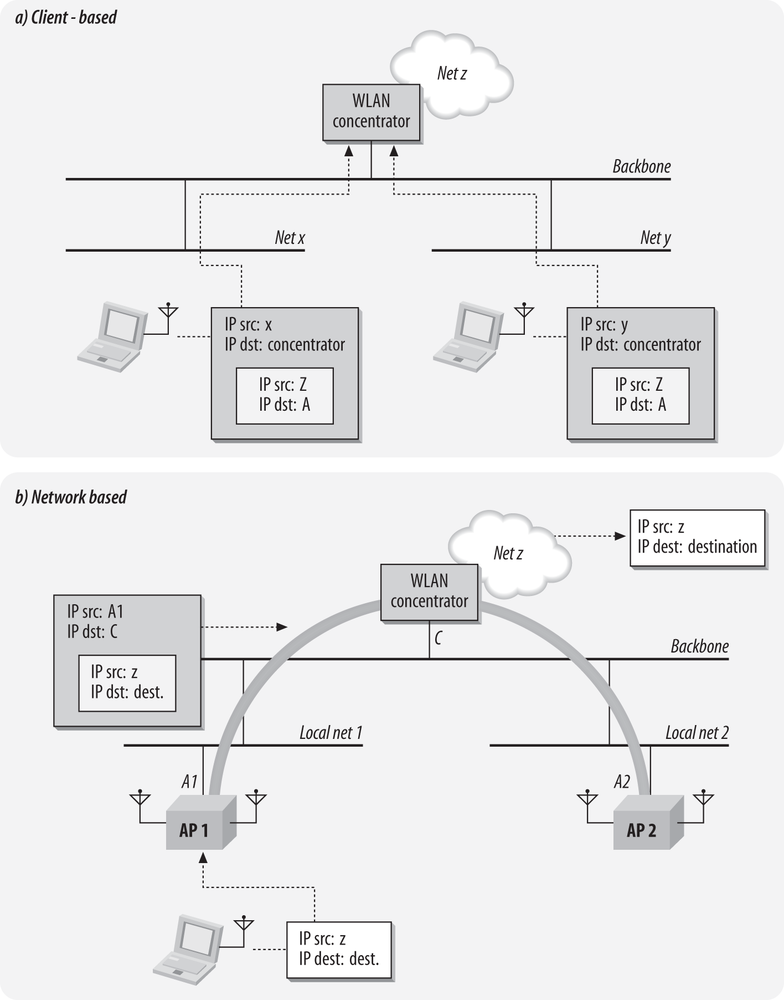
Figure 21-6 shows how mobility can be grafted on to a collection of scattered networks. In Figure 21-6 (a), clients are given a local IP address that is tied to location. The local networks are represented by Net X and Net Y. Upon connection, clients are issued addresses from the IP space assigned to the X and Y networks. However, the client also initiates a connection to a central concentration point. Clients logically attach to the concentrator, and receive an address from a network logically attached to the concentrator, which is denoted by Net Z in the diagram. Packets sent from the client use its central anchor point address, Z, as the source, but they are bundled into a tunnel for transmission. Replies are routed back to Z, but the concentrator maintains a mapping of addresses on network Z to location-based addresses. Note that Figure 21-6 (a) does not specify any particular tunneling method. Mobile IP works in essentially this way, and a few specialized IPsec clients work this way as well.
Although the approach of Figure 21-6 (a) is conceptually straightforward, it requires changing the software on all wireless devices. In addition to the administrative challenge of loading new software on any wireless device and the potential instability of changing the network stack, it is likely that vendors of this software would not be able to support every operating system platform. Even if the major operating systems were supported, many embedded devices could not be. Figure 21-6 (b) offers an alternative approach where the tunneling is moved into the network. In Figure 21-6 (b), access points do not connect to a backbone network for the purpose of delivering traffic. The backbone network is used only to connect APs to the traffic concentration point. Any frames or packets from the client are delivered through the tunnel to the concentrator device, where they are sent on to the rest of the network. It does not matter where clients attach to the network because traffic is always routed to the traffic concentration point.
In both of the cases in Figure 21-6, the key is that client IP addresses become location-independent. IP addresses on local networks are used for the purpose of connectivity, but the logical point of attachment to the network is through a defined anchor point, just as in the previous topology.
Tunneling approaches work to unite disjointed coverage areas. In the first topology, mobility was all-or-nothing. Figure 21-5’s disjointed coverage areas force network architects to design mobility around areas that are most important to users, subject to the constraints of the local network design. By using a tunneling approach, the network can be reunited into a single mobility cloud, but without the need to re-engineer the entire network backbone. There is, however, the difficulty of configuring any tunneling and working out the overlay topology.
Security
One of the advantages of this architecture is that it is easy to use it with IPsec. IPsec is a suite of strong, trusted encryption protocols that have been widely used in hostile network environments, and that trust has allowed IPsec to be used to protect a great deal of sensitive information traversing the Internet. Many organizations that have a need to protect private personal information make extensive use of IPsec.
One drawback to relying on network-layer security is that it gives malicious attackers a foothold on your network. If association to the network is not protected, then attackers may obtain a network address and start launching attacks against against other clients or the network infrastructure outside the firewall. Strong firewall protection is a must to contain any attacks originating on the untrusted network. Host security is also extremely important because devious attackers would also likely attempt to subvert host security on the clients to hijack VPN tunnels, so personal firewall software is a must.
IPsec was designed with a point-to-point architecture in mind. When used between major sites, traffic is inherently point-to-point. However, LANs are not meant to be point to point networks. (Just ask anybody who has experience with ATM LAN Emulation!) Applications that make use of multicast will probably not work with IPsec without modification or network reconfiguration.
Performance
Providing connectivity through isolated islands gives this topology a distinct advantage over the first topology. Rather than one gateway device that handles all traffic from the wireless LAN, each island gateway must be capable of fowarding only that island’s traffic. Multiple choke points between wireless and wired networks allow each choke point to be a smaller, and therefore less expensive, device.
This architecture is frequently used with IPsec, often with an existing VPN termination device. One problem that can occur is that VPN devices are often sized for remote user termination. If LAN users suddenly start using IPsec, the existing VPN termination device may prove inadequate. A centrally located VPN device must be able to provide encryption for the entire wireless LAN traffic load; each 802.11b access point may offer a traffic load of up to 6 Mbps each, while an 802.11a or 802.11g access point may serve up a load approaching 30 Mbps.
There are many different tunneling options available for this broad topology. Tunneling always imposes a network overhead because it requires encapsulation. An additional challenge that wireless LAN devices must face is the need for fragmentation in tunneling protocols. Many of the LAN backbones used to connect access points do not support jumbo frames, so any tunneling protocol that runs over Ethernet must incorporate fragmentation and reassembly. Beyond the fragmentation overhead, any tunneling protocol requires additional header information. Depending on the protocol selected, fragmentation overhead may be nontrivial.
Running user traffic across a network backbone may diminish the service quality. Large networks may not be able to provide consistent low-latency forwarding performance between the access points and the concentration device, especially if the tunneling mechanism is implemented over a best-effort protocol like IP. In the case of user data traffic, any service quality diminishment is likely to be negligible. If the wireless network must be used to support voice protocols, however, the impact of tunneling may be more substantial.
Backbone
Compared to the single-subnet architecture, this topology integrates much better with networks that cannot support a single VLAN everywhere. At worst, this architecture requires creating several miniature single-subnet backbones. If tunneling functions are moved into the network, though, it is possible to extend networks out to remote locations without any backbone work.
Client
VPN software is typically used with this approach, which requires configuring client software on any machine that will use the wireless network. In some organizations, this may not represent a large burden, especially if most of the users already have VPN software. However, many organizations limit the number of users given remote access privileges to limit the amount of client integration work necessary, or prevent remote access devices from being overwhelmed with the load. If you work for such an organization, there is a significant client software installation burden with a widespread wireless deployment. As mentioned previously, personal firewall software is mandatory to protect each client from link-layer attacks. Give preference to VPN clients that include personal firewall software, especially if the personal firewall policies can be centrally managed.
Topology 3: Dynamic VLAN Assignment
Both the single-subnet and island topologies are designed around the limitations of the first access points to hit the market. Early access points attached all users to the same network, and did very little to enforce different privileges on different groups of users. This topology was the first to embrace the wired world of VLANs and make them available to user groups. Instead of building a second parallel network, this topology extends the existing network, complete with any security systems and filters, into the wireless realm.
802.1X is the cornerstone of dynamic VLAN assignment. It plugs the wireless network neatly into an existing authentication infrastructure. Authentication servers have user profiles and privileges, and can map that privilege information on to the wireless LAN. For example, Figure 21-7 shows a RADIUS server handing out VLAN assignments to the access point. As part of the RADIUS access accept message, it includes an attribute that assigns an authenticated user to a particular VLAN. Based on that information, the access point tags any frames from the user on to the appropriate VLAN.
The advantage of doing authentication at the link layer, rather than a higher layer, is that users can be placed on a particular network with the privileges associated with that network from the start. When the access point receives the Access Accept message from the RADIUS server, it sends an 802.1X EAP Success message to the client. Network card drivers on the client interpret the EAP Success message as the equivalent event to a “link up” message, and send their DHCP request and begin initializing the network stack. By the time the network stack has begun to initialize, the network has already automatically configured itself to restrict the user to a particular set of access rights.

Mobility
At the highest level, mobility in this topology is identical to the first topology. Users are attached to a consistent VLAN throughout the network, and thus can maintain the same IP address regardless of location. With the same IP address, any transport-layer state or application state remains valid throughout the life of the connection.
However, the underlying implementation of mobility offers several advantages over the single-subnet architecture. The first set of advantages have to do with the use of authentication services. Attributes from the RADIUS server ensure that users are always attached to the same VLAN, and hence, they stay attached to the same logical point on the network.
In addition to aiding mobility, providing consistent VLAN attachment can make other services work better. Providing mobility at the link layer reduces the apparent mobility to higher-layer protocols, and hence, the amount of work required of them. IPsec tunnels stay up consistently because the IP address does not change. Likewise, Mobile IP location updates are not necessary because the IP address is maintained.
Security
Because the VLAN assignment is based on 802.1X and RADIUS, security in this topology is based on dynamically generated keys at the link layer, either through dynamic WEP, WPA, or CCMP. Dynamic key generation enables the second benefit of using authentication services. Once users have been identified, they can be separated into groups for different security treatment.
To separate traffic in the air between user groups, access points use multiple key sets. Upon authentication, every user is given a default (broadcast) key, and a key mapping (unicast) key. Broadcast domains are defined by the stations in possession of the same broadcast key. In Figure 21-8, the two users on the left are part of the same user group, and share the same broadcast key. When one sends, say, an ARP request, the other responds. Users who are part of a different broadcast domain are not able to decrypt and process the frame because they have a different broadcast key. Although user groups share the same radio capacity, they are not members of the same user group and remain separated over the radio network.

Furthermore, the separation of user groups by VLAN allows the application of differentiated services, as shown in Figure 21-9. One common use of user identification and differentiation is to offer guest services. Internal users are identified and authenticated against a user database, and then connected to the internal network. Guest users do not have accounts on the main user database and cannot authenticate to the network. After failing to do so, they are attached to a different logical network. Guest networks may have “splash pages” that require a click-through agreement to not abuse the network; some organizations may also wish to require payment for guest access.

An additional advantage to link-layer security is that multicast is well-integrated into the security protocol. LAN protocols often make heavy use of multicast or broadcast frames, and the use of multicast LAN frames can only increase. Wireless networks are attractive because of their flexibility and location-independence. Protocols that assist in the automatic discovery and configuration of new devices usually rely heavily on multicast frames.
One downside to this topology relates to bureaucratic requirements around security. At the time this book was written, link-layer security could not comply with FIPS-140, the U.S. federal government’s network security standard, because of a subtle flaw with the dynamic key derivation algorithms in 802.11i. Although the encryption mode used by CCMP is approved, a small change to the key derivation algorithm is likely to be required before 802.11i-based networks can meet the FIPS-140 bar.
Performance
This architecture does not necessarily require a choke point. Switching frames at the network edge eliminates the requirement for an oversized packet forwarding device. Wireless LANs are access networks, so by definition, a wireless LAN should not be able to overload a well-built network core. One of the downsides of this architecture, however, is that it is best deployed around a big, fast switched core.
Backbone
Redesigning a network to use VLAN information dynamically can often impose a substantial redesign of the the network backbone. What is required depends on how the wireless LAN connects to the network core. When a wireless LAN connects to the core to attach users to multiple networks, it typically uses an 802.1Q tagged link. Wireless LAN products vary in how widely tagging is used, and to what extent the tags must be pushed across the network. In broad terms, there are two major ways to push VLAN information out to access points.
- Direct core connection
When the connection to the network core is made directly, the access points must connect directly to the network core, usually through an 802.1Q-tagged link.
Note that the connection to the core is the logical connection from the access points. With some products, the access points must connect directly to the core, which means that every switch port used to connect to an access point must support any VLAN used by wireless users. Direct core connections for every access point imposes a huge backbone engineering requirement, and may even rule out the use of this topology. If the VLANs do not exist in every closet where APs connect, they must be extended everywhere before the wireless deployment can even begin.
Direct connections to the core may also pose a security risk. Most APs authenticate users, but the APs themselves do not authenticate. An attacker who replaces an AP with his own device may have a direct connection to the network core.
- Indirect (tunneled) core connection
Instead of requiring every access point to connect directly to the core, some products allow the use of tunneling protocols to avoid significant changes to the backbone. Users connect to an access point, but the AP tunnels the user’s frames to a remote location before they are placed on to the core network. Tunneling can be accomplished between access points, or between an access point and an aggregation device. The tunneling protocol may be proprietary, or it may be based on a simple encapsulation standard like the Generic Routing Encapsulation (GRE), IP in IP, or the Point-to-Point Protocol over Ethernet (PPPoE).
In Figure 21-10 (a), there are two APs on separate VLANs. After user authentication completes, the AP is responsible for connecting the user on to the appropriate VLAN. If the AP is directly attached, then the connection is easy. When the AP is not directly attached to the VLAN the user must be connected to, the tunnel is built between APs. AP2 locates the VLAN the user should be attached to, and sends user frames through the tunnel to AP1. AP1 then sends frames out on to the network normally. The user’s logical attachment remains AP1, no matter what the physical location is. Depending on the implementation, it may be necessary to prevent tunneling across long distances. If the two networks are separated by state lines, or even an ocean, tunneling traffic is likely to result in user dissatisfaction.
In Figure 21-10 (b), the attachment is centralized at the core of the network rather than being distributed at the edge. Frames received by the access points are shuttled up through the tunnel to the concentrator, where they are placed on the appropriate network. VLAN information is only relevant at the end of a frame’s journey through the wireless LAN system. Until the frames reach the concentrator, they do not carry VLAN tags. The advantage of a remote tunneling system is that users can be attached to VLANs that are not locally present. The VLANs need to be made available only to the concentrator.
Of the two methods, tunneled connections tend to impose less of a backbone engineering requirement because tags can be distributed on a more local basis. In the direct connect case, every port connected to an access point must carry the complete set of VLANs users may want to work with. The backbone impact is just as great as the first topology for each VLAN. In contrast, indirect connections can span wider areas by operating outside of a spanning tree domain, and configuration of individual switch ports may be easier.
Client
802.1X supplicants are now built-in to the most common client operating systems. Windows 2000, Windows XP, and Mac OS X 10.3 all have 802.1X supplicant software built into the operating system. Provided that you wish to use one of the authentication protocols supported by the operating system’s supplicant, there is no client installation to worry about. Furthermore, the built-in supplicant configuration can often be assisted by the use of large-scale system administration tools to distribute the required certificates or configuration information.
Topology 4: Virtual Access Points
A straightforward application of 802.1X and VLAN assignment leads directly to the previous topology. However, it works best when the network has only one class of user—and that is hardly realistic. Most networks are now built to connect employees to internal resources while simultaneously giving guests access to the Internet. Supporting multiple classes of user is becoming much more common, but it creates additional work for security architects. Different logical networks must be run in parallel, often with vastly different security models.

One method of building multiple logical networks is to build multiple physical networks, and manage each separately. Competition for network administrator time, access point locations, power and network connections, and radio resources makes building multiple physical networks unproductive. Instead, architects are turning to virtual access points, which enable multiple logical networks to be built on a single physical infrastructure. The physical network owner is responsible for maintaining the infrastructure as a common carrier, and serving as a transit network to other existing networks.
Several years ago, airports woke up to the possibility of using 802.11 as a network medium to connect business travelers (and their wallets) to the Internet. In the first wave, airports worked with specialist integrators to build a single wireless LAN that looked something like the first topology in this chapter. It could be used by business travelers, but was not at all suited to use by anybody else. Many applications of wireless networking went unheeded. Wireless networks are ideal for providing connections that may need to be moved and changed on a regular basis, such as retail kiosks or even the airline equipment at gates. It is easy to understand why a credit-card processing service or an airline would feel that a network designed for road warriors did not provide adequate security.
With a network designed around virtual APs, there is one set of physical infrastructure, owned by the building owner. The building owner is responsible for frequency coordination throughout the building.[92] From a monetary perspective, the single physical network is also the only game in town, and the building owner can charge for access to the network. In office buildings designed for multiple tenants, the owner may choose to use the wireless network as an amenity to make tenancy more attractive.
Virtual APs may also make a great deal of sense for the network users. With one organization handling physical installation, there is no overlapping installation effort, and it lessens turf wars over radio spectrum. A virtual AP can offer the same services as a dedicated AP, but a virtual AP is often cheaper to install because of the shared infrastructure. The most advanced virtual APs look exactly like multiple standalone APs. I expect that the management of virtual AP systems offer the ability to extend management infrastructure to the users, so that there is a low-level administration interface plus the ability to configure virtual networks for every customer subscribing to a multitenant network service.
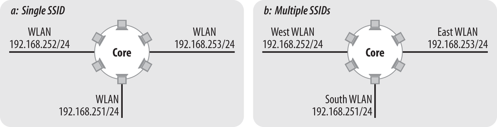
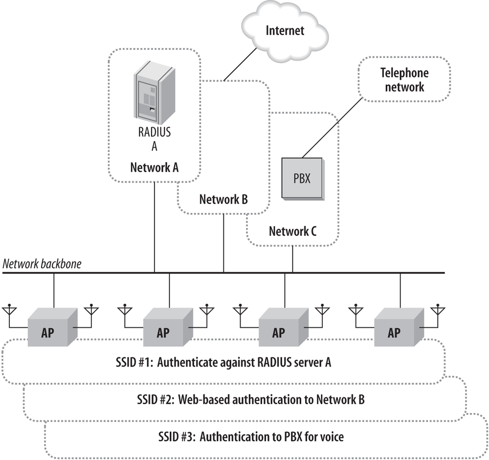
Figure 21-11 shows what a network built on virtual access points would look like. In essence, it allows the network administrator to create several copies of the dynamic VLAN topology on one set of physical infrastructure, with each virtual network administered. In the figure, there are three distinct networks to be extended by the wireless LAN. Network A is a typical corporate network. Users who wish to gain access to it must have accounts on the corporate RADIUS server. Network B is a hot-spot service provider. For device-independence, many service providers use web-based authentication systems that trap user requests until users have identified themselves and made appropriate arrangements to pay for network access. Finally, Network C is designed to support voice over IP, and has an IP PBX system. One set of access points is deployed to support all three networks. One SSID identifies Network A. That SSID has a security configuration that requires 802.1X authentication against the RADIUS server on Network A, and it may be that systems attaching to the network have appropriate client software installed, such as antiviral protection. SSID A may support several different VLANs on Network A, depending on how the RADIUS server is configured. Network A is also configured to support strong encryption. Network B is supported by a second SSID that is configured for web-based authentication. Once users authenticate through the web system, they are allowed Internet access. Network B has no encryption because the service provider does not want to restrict subscriber computing platforms or require special client software beyond a web browser. SSID C is deployed to support voice over IP. Traffic on SSID C is likely prioritized over the other two because of the tighter quality of service requirements for voice traffic. How devices authenticate against SSID C depends on the handsets in use. Many VoIP handsets do not yet support 802.1X, leaving network administrators to rely on MAC filtering and static WEP for security.
Mobility
This topology provides essentially the same mobility as the previous topology. VLANs can be dynamically instantiated at the edge to connect users, so client stations are dynamically attached to the correct point on the network. As in the previous case, additional protocols may be used to extend mobility across more than a single VLAN domain.
With virtual access points, limiting mobility may be important. This architecture is designed around providing service, and it may be that service should not be ubiquitous. If an office building were to provide connectivity for tenants, the owners may choose to limit where tenants can connect. Rather than connecting anywhere in the building, the service may be limited to a particular floor or wing. If an airport were to deploy a network using virtual access points, the public hot spot service providers would likely be restricted to the public areas, while the airport operational network was available through more of the facility. Different products provide alternate approaches to limiting mobility. As with many other network control functions, your preference should be for centrally-administered access controls.
Security
Due to the tie-in with the link layer, this topology is often used in conjunction with 802.1X and RADIUS. 802.1X should not be a requirement. Each of the virtual networks should have its own security configuration, which would allow every customer to enforce their own security policy. Different customers may have different requirements, and a network built on virtual access points should accommodate any reasonable security policy. For example, most hot spot providers are running web-based login systems. While a web-based login system may be good enough for some applications, legal requirements would impose much stricter handling on a system that accessed personally-identifiable information. Virtual AP-based networks need to accommodate both types of access simultaneously.
Performance
Performance is not constrained by a choke point anywhere. With the wireless network connecting directly into a larger network core, the only performance constraint is congestion on the core.
The biggest problem facing a multitenant network is that the network owner has to design a network with enough capacity for all the users. In the case of a private network owned and operated by one organization for its own purposes, it may be possible to estimate the network requirements. With a network service provided to others, the estimates obtained by consulting with users may be somewhat murky.
One additional item worthy of note is that analyzers may report overloaded channels because a single AP acts as multiple virtual APs. Provided that the network has been designed around the total throughput required by all users, it is acceptable to have multiple networks over the air.
Backbone
Like any other AP, a virtual AP connects a radio network to a wired network. In the case of a virtual AP, both the radio and fixed networks may be created over a shared physical infrastructure. Rather than one wired network, or a set of networks owned by one organization, there may be a need to connect to several customer networks on the back end. When all the networks belong to one organization, they probably have similar security requirements and can be connected easily to wireless networks. Mapping wireless networks on to the wired networks of several different (and possibly competing) customers may require additional measures to ensure security and traffic separation.
Client
As with the other topologies, the client software load depends a great deal on the security protocols. At the easy end of the spectrum, a network can be deployed using web-based authentication without requiring any client software. At the most difficult, the network can use several security protocols, each with its own client software requirement. One of the advantages to virtual AP-based networks is that the virtual APs may be used to create several networks, each with its own special security configuration.
Choosing Your Logical Architecture
When choosing a logical architecture, you must weigh several trade-offs. Some of these are security trade-offs are discussed in the next chapter. Many are, however, a matter of balancing performance, simplicity, or functionality.
Mobility is a baseline function that should be provided by any architecture you choose. 802.11 provides for mobility within an extended service set, and that ESS must be visible to the client as a single IP subnet. All of the architectures presented here attach clients to a single subnet, although the mechanics of how they do so differ radically.
For small-scale deployments using a handful of APs, any of the architectures work. The first two are easy to set up on a very small scale, and may have the advantage for cost-conscious deployments that will never grow beyond the initial handful of APs.
The IEEE’s inter-access point protocol provides link-layer mobility only. Crossing router boundaries into new broadcast domains requires network-layer coordination between wireless LAN access devices. At the time this book was written, subnet mobility generally required picking a single-vendor solution. Mobile IP is an open standard, but it is not widely implemented.
Clients must perceive that they are attached to a single IP subnet, no matter what the physical location of their attachment. This does not, however, require that all clients be attached to the same subnet. Multiple subnets may overlap “over the air.” Multiple subnets over the air offer the ability to more finely control user access privileges and differentiate between user groups, but require the use of 802.1X.
What limitations does the existing network impose? Baggage from past decisions may limit the choices that you can make.
A sprawling network with a large diameter may not be able to extend VLANs across the entire network due to spanning tree limitations. This may rule out the use of a single wireless VLAN, or a dynamic VLAN model where the access points must be connected to the core.
The dynamic VLAN topology may depend on widely distributing 802.1Q tags throughout your network. If VLAN information is not already available, network administrators must find a way to distribute it to all the locations that support a wireless network. Products that require direct connection into the core are incompatible with a routed core network.
Networks may have choke points in a variety of places. Pre-existing choke points may limit the number of wireless devices that can be attached in many locations. If your desired architecture intentionally introduces a choke point, it must be fast enough to not limit throughput.
The choice of network topology may be driven in part by the security protocols used on the network. Dynamic VLAN assignment is possible only with 802.1X, so the last two topologies work best for administrators who want to use link layer security mechanisms. The first two topologies are much more suited to use with network-layer security based on IPsec and personal firewall software. This chapter has not directly explored the trade-off between the different security approaches, but the next chapter does.
Static addressing is not necessary. It adds needless complexity with very little benefit in return. Network administrators must manage address allocation, and get directly involved in adding new systems to the wireless LAN.
Static addressing provides only a minimal direct security benefit. Source IP addresses are not authenticated by the sender, and attackers are likely to learn the IP addresses being used on the wireless network unless you employ strong link-layer protection.
Tracking users is better done through the user-based networking that 802.1X provides. With a username available to the network through the RADIUS server, there is no need to associate a user with an IP address. The user can be associated with the username instead.
Dynamic addressing minimizes the chance that two users may accidentally be assigned the same address. Only one DHCP server is needed for several VLANs with judicious use of DHCP helper; if a DHCP server already exists, there may not be any reason to use another one.
Table 21-4 summarizes the different factors discussed in this chapter. Security is too complex to be reduced to a simple table entry, so it receives the full attention of the next chapter. As you consider this table and a purchase decision, keep in mind that some products work with certain topologies better than others.
Single subnet | ET phone home | Dynamic VLAN | Virtual AP | |
Mobility | High if VLAN is large; limited by maximum 802.1D diameter | Depends on size of islands | High | High; but enforcing limitations may be important |
Performance | Depends on choke point capacity | Depends on concentrator capacity | High due to distributed encryption | Same as dynamic VLAN |
Backbone | High; though may depend on existing network | Varies with range of mobility[a] | Depends on type of connection to network core | Same as dynamic VLAN |
Client | Depends on client software[b] | Depends on client software[c] | Built-in to operating system | Same as dynamic VLAN; handles multiple client security models better |
IP addressing | High (new subnets and routing) | High (new subnets and routing) | Not required | Same as dynamic VLAN |
[a] Newer products may reduce the backbone impact by logically attaching access points to a control device in the network. [b] Both the single subnet and central concentrator architectures are typically used with VPN software for additional security. Obviously, if VPN software is used, the amount of client integration work is much larger. [c] Both the single subnet and central concentrator architectures are typically used with VPN software for additional security. Obviously, if VPN software is used, the amount of client integration work is much larger. | ||||
[88] Indeed, the early adopters of wireless LAN technology tended to be in organizations where the work was mobile—health care, logistics, and education.
[89] The effective throughput is actually much lower. Quantifying the exact impact of the protocol overhead is very difficult; for one straw-man calculation, see http://www.oreillynet.com/pub/a/wireless/2003/08/08/wireless_throughput.html.
[90] This is a bit of a simplification. ESSIDs are only network names for infrastructure networks. As always, this book generally assumes that you are running an infrastructure network, not an ad hoc network.
[91] Very large homes may require multiple APs. Generally speaking, an AP should be good for coverage over 3,000-5,000 square feet, which is sufficient for all but the largest homes.
[92] Newer leases for multitenant buildings are increasingly being written so that the owner retains control of the electromagnetic spectrum and can construct a building-wide network without working around tenant equipment, although the FCC takes a dim view of these provisions.