
Chapter 11. The Frequency-Hopping (FH) PHY
Of all the physical layers standardized in the first draft of 802.11 in 1997, the frequency-hopping spread spectrum (FH or FHSS) layer was the first layer to see widespread deployment. The electronics used to support FH modulation are relatively cheap and do not have high power requirements. Initially, the main advantage to using frequency-hopping networks was that a greater number of networks could coexist, and the aggregate throughput of all the networks in a given area was high. At this point, however, FH networks are largely a footnote in the history of 802.11. Although it is a standard, only one vendor still manufactures and sells frequency-hopping systems, and they are being phased out. Higher-throughput specifications have demolished the advantage of aggregate throughput, and newer chipsets are less power-hungry.
This chapter describes the basic concepts used by the frequency-hopping PHY and the modulation techniques used. It also shows how the physical layer convergence procedure prepares frames for transmission on the radio link and touches briefly on a few details of the physical medium itself. At this point, the FH PHY is largely a footnote in the history of 802.11, so you may want to skip this chapter and move ahead to the next section on the direct-sequence PHY. However, understanding how 802.11 technology developed will give you a better feeling for how all the pieces fit together.
Frequency-Hopping Transmission
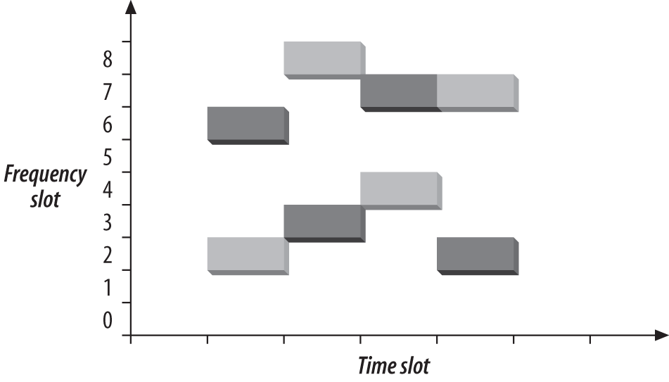
Frequency hopping depends on rapidly changing the transmission frequency in a predetermined, pseudorandom pattern, as illustrated in Figure 11-1. The vertical axis of the graph divides the available frequency into a number of slots. Likewise, time is divided into a series of slots. A hopping pattern controls how the slots are used. In the figure, the hopping pattern is {2,8,4,6}. Timing the hops accurately is the key to success; both the transmitter and receiver must be synchronized so the receiver is always listening on the transmitter’s frequency.

Frequency hopping is similar to frequency division multiple access (FDMA) but with an important twist. In FDMA systems, each device is allocated a fixed frequency. Multiple devices share the available radio spectrum by using different frequencies. In frequency-hopping systems, the frequency is time-dependent rather than fixed. Each frequency is used for a small amount of time, called the dwell time.
Among other things, frequency hopping allows devices to avoid interfering with primary users assigned to the same frequency band. It works because primary users are assigned narrow frequency bands and the right to transmit at a power high enough to override the wireless LAN. Any interference caused by the secondary user that affects the primary user is transient because the hopping sequence spreads the energy out over a wide band.[51] Likewise, the primary user only knocks out one of the spread-spectrum device’s slots and looks like transient noise. Figure 11-2 shows the result when frequency slot 7 is given to a primary user. Although the transmission in the fourth time slot is corrupted, the other three transmissions succeed.
If two frequency-hopping systems need to share the same band, they can be configured with different hopping sequences so they do not interfere with each other. During each time slot, the two hopping sequences must be on different frequency slots. As long as the systems stay on different frequency slots, they do not interfere with each other, as shown in Figure 11-3. The gray rectangles have a hopping sequence of {2,8,4,7}, as in the previous figures. A second system with a hopping sequence of {6,3,7,2} is added. Hopping sequences that do not overlap are called orthogonal. When multiple 802.11 networks are configured in a single area, orthogonal hopping sequences maximizes throughput.

802.11 FH Details
802.11 divides the microwave ISM band into a series of 1-MHz channels. Approximately 99% of the radio energy is confined to the channel. The modulation method used by 802.11 encodes data bits as shifts in the transmission frequency from the channel center. Channels are defined by their center frequencies, which begin at 2.400 GHz for channel 0. Successive channels are derived by adding 1-MHz steps: channel 1 has a center frequency of 2.401 GHz, channel 2 has a center frequency of 2.402 GHz, and so on up to channel 95 at 2.495 GHz. Different regulatory authorities allow use of different parts of the ISM band; the major regulatory domains and the available channels are shown in Table 11-1.
Regulatory domain | Allowed channels |
U.S. (FCC) | 2 to 79 (2.402-2.479 GHz) |
Canada (IC) | 2 to 79 (2.402-2.479 GHz) |
Europe (excluding France and Spain) (ETSI) | 2 to 79 (2.402-2.479 GHz) |
France | 48 to 82 (2.448-2.482 GHz) |
Spain | 47 to 73 (2.447-2.473 GHz) |
Japan (MKK) | 73 to 95 (2.473-2.495 GHz) |
The dwell time used by 802.11 FH systems is 390 time units, which is almost 0.4 seconds. When an 802.11 FH PHY hops between channels, the hopping process can take no longer than 224 microseconds. The frequency hops themselves are subject to extensive regulation, both in terms of the size of each hop and the rate at which hops must occur.
802.11 Hop Sequences
Mathematical functions for deriving hop sets are part of the FH PHY specification and are found in clause 14.6.8 of the 802.11 specification. As an example, hopping sequence 1 for North America and most of Europe begins with the sequence {3, 26, 65, 11, 46, 19, 74, 50, 22, ...}. 802.11 further divides hopping sequences into nonoverlapping sets, and any two members of a set are orthogonal hopping sequences. In Europe and North America, each set contains 26 members. Regulatory authorities in other areas have restricted the number of hopped channels, and therefore each set has a smaller number of members. Table 11-2 has details.
Joining an 802.11 Frequency-Hopping Network
Joining a frequency-hopping network is made possible by the standardization of hop sequences. Beacon frames on FH networks include a timestamp and the FH Parameter Set element. The FH Parameter Set element includes the hop pattern number and a hop index. By receiving a Beacon frame, a station knows everything it needs to synchronize its hopping pattern.
Based on the hop sequence number, the station knows the channel-hopping order. As an example, say that a station has received a Beacon frame that indicates that the BSS is using the North America/Europe hop sequence number 1 and is at hop index 2. By looking up the hop sequence, the station can determine that the next channel is 65. Hop times are also well-defined. Each Beacon frame includes a Timestamp field, and the hop occurs when the timestamp modulo dwell time included in the Beacon is 0.
ISM Emission Rules and Maximum Throughput
Spectrum allocation policies are the limiting factor of frequency-hopping 802.11 systems. As an example, consider the three major rules imposed by the FCC in the U.S.:[52]
There must be at least 75 hopping channels in the band, which is 83.5-MHz wide.
Hopping channels can be no wider than 1 MHz.
Devices must use all available channels equally. In a 30-second period, no more than 0.4 seconds may be spent using any one channel.
Of these rules, the most important is the second one. No matter what fancy encoding schemes are available, only 1 MHz of bandwidth is available at any time. The frequency at which it is available shifts continuously because of the other two rules, but the second rule limits the number of signal transitions that can be used to encode data.
With a straightforward, two-level encoding, each cycle can encode one bit. At 1 bit per cycle, 1 MHz yields a data rate of 1 Mbps. More sophisticated modulation and demodulation schemes can improve the data rate. Four-level coding can pack 2 bits into a cycle, and 2 Mbps can be squeezed from the 1-MHz bandwidth.
The European Telecommunications Standards Institute (ETSI) also has a set of rules for spread-spectrum devices in the ISM band, published in European Telecommunications Standard (ETS) 300-328. The ETSI rules allow far fewer hopping channels; only 20 are required. Radiated power, however, is controlled much more strictly. In practice, to meet both the FCC and ETSI requirements, devices use the high number of hopping channels required by the FCC with the low radiated power requirements of ETSI.
Effect of Interference
802.11 is a secondary use of the 2.4-GHz ISM band and must accept any interference from a higher-priority transmission. Catastrophic interference on a channel may prevent that channel from being used but leave other channels unaffected. With approximately 80 usable channels in the U.S. and Europe, interference on one channel reduces the raw bit rate of the medium by approximately 1.25%. (The cost at the IP layer will be somewhat higher because of the interframe gaps, 802.11 acknowledgments, and framing and physical-layer covergence headers.) As more channels are affected by interference, the throughput continues to drop. See Figure 11-4.

Gaussian Frequency Shift Keying (GFSK)
The FH PHY uses Gaussian frequency shift keying (GFSK).[53] Frequency shift keying encodes data as a series of frequency changes in a carrier. One advantage of using frequency to encode data is that noise usually changes the amplitude of a signal; modulation systems that ignore amplitude (broadcast FM radio, for example) tend to be relatively immune to noise. The Gaussian in GFSK refers to the shape of radio pulses; GFSK confines emissions to a relatively narrow spectral band and is thus appropriate for secondary uses. Signal processing techniques that prevent widespread leakage of RF energy are a good thing, particularly for secondary users of a frequency band. By reducing the potential for interference, GFSK makes it more likely that 802.11 wireless LANs can be built in an area where another user has priority.
2-Level GFSK
The most basic GFSK implementation is called 2-level GFSK (2GFSK). Two different frequencies are used, depending on whether the data that will be transmitted is a 1 or a 0. To transmit a 1, the carrier frequency is increased by a certain deviation. Zero is encoded by decreasing the frequency by the same deviation. Figure 11-5 illustrates the general procedure. In real-world systems, the frequency deviations from the carrier are much smaller; the figure is deliberately exaggerated to show how the encoding works.
The rate at which data is sent through the system is scalled the symbol rate. Because it takes several cycles to determine the frequency of the underlying carrier and whether 1 or 0 was transmitted, the symbol rate is a very small fraction of the carrier frequency. Although the carrier frequency is roughly 2.4 billion cycles per second, the symbol rate is only 1 or 2 million symbols per second.

Frequency changes with GFSK are not sharp changes. Instantaneous frequency changes require more expensive electronic components and higher power. Gradual frequency changes allow lower-cost equipment with lower RF leakage. Figure 11-6 shows how frequency varies as a result of encoding the letter M (1001101 binary) using 2GFSK. Note that the vertical axis is the frequency of the transmission. When a 1 is transmitted, the frequency rises to the center frequency plus an offset, and when a 0 is transmitted, the frequency drops by the same offset. The horizontal axis, which represents time, is divided into symbol periods. Around the middle of each period, the receiver measures the frequency of the transmission and translates that frequency into a symbol. (In 802.11 frequency-hopping systems, the higher-level data is scrambled before transmission, so the bit sequence transmitted to the peer station is not the same as the bit sequence over the air. The figure illustrates how the principles of 2GFSK work and doesn’t step through an actual encoding.)

4-Level GFSK
Using a scheme such as this, there are two ways to send more data: use a higher symbol rate or encode more bits of information into each symbol. 4-level GFSK (4GFSK) uses the same basic approach as 2GFSK but with four symbols instead of two. The four symbols (00, 01, 10, and 11) each correspond to a discrete frequency, and therefore 4GFSK transmits twice as much data at the same symbol rate. Obviously, this increase comes at a cost: 4GFSK requires more complex transmitters and receivers. Mapping of the four symbols onto bits is shown in Figure 11-7.

With its more sophisticated signal processing, 4GFSK packs multiple bits into a single symbol. Figure 11-8 shows how the letter M might be encoded. Once again, the vertical axis is frequency, and the horizontal axis is divided into symbol times. The frequency changes to transmit the symbols; the frequencies for each symbol are shown by the dashed lines. The figure also hints at the problem with extending GFSK-based methods to higher bit rates. Distinguishing between two levels is fairly easy. Four is harder. Each doubling of the bit rate requires that twice as many levels be present, and the RF components distinguish between ever-smaller frequency changes. These limitations practically limit the FH PHY to 2 Mbps.

FH PHY Convergence Procedure (PLCP)
Before any frames can be modulated onto the RF carrier, the frames from the MAC must be prepared by the Physical Layer Convergence Procedure (PLCP). Different underlying physical layers may have different requirements, so 802.11 allows each physical layer some latitude in preparing MAC frames for transmission over the air.
Framing and Whitening
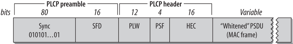
The PLCP for the FH PHY adds a five-field header to the frame it receives from the MAC. The PLCP is a relay between the MAC and the physical medium dependent (PMD) radio interface. In keeping with ISO reference model terminology, frames passed from the MAC are PLCP service data units (PSDUs). The PLCP framing is shown in Figure 11-9.
- Preamble
As in a wired Ethernet, the preamble synchronizes the transmitter and receiver and derives common timing relationships. In the 802.11 FH PHY, the Preamble is composed of the Sync field and the Start Frame Delimiter field.
- Sync
The sync field is 80 bits in length and is composed of an alternating zero-one sequence (010101...01). Stations search for the sync pattern to prepare to receive data. In addition to synchronizing the sender and receiver, the Sync field serves three purposes. First of all, the presence of a sync signal indicates that a frame is imminent. Second, stations that have multiple antennas to combat multipath fading or other environmental reception problems can select the antenna with the strongest signal. Finally, the receiver can measure the frequency of the incoming signal relative to its nominal values and perform any corrections needed to the received signal.
- Start Frame Delimiter (SFD)
As in Ethernet, the SFD signals the end of the preamble and marks the beginning of the frame. The FH PHY uses a 16-bit SFD: 0000 1100 1011 1101.
- Header
The PLCP header follows the preamble. The header has PHY-specific parameters used by the PLCP. Three fields comprise the header: a length field, a speed field, and a frame check sequence.
- PSDU Length Word (PLW)
The first field in the PLCP header is the PLW. The payload of the PLCP frame is a MAC frame that may be up to 4,095 bytes long. The 12-bit length field informs the receiver of the length of the MAC frame that follows the PLCP header.
- PLCP Signaling (PSF)
Bit 0, the first bit transmitted, is reserved and set to 0. Bits 1-3 encode the speed at which the payload MAC frame is transmitted. Several speeds are available, so this field allows the receiver to adjust to the appropriate demodulation scheme. Although the standard allows for data rates in increments of 500 kbps from 1.0 Mbps to 4.5 Mbps, the modulation scheme has been defined only for 1.0 Mbps and 2.0 Mbps.[54] See Table 11-3.
- Header Error Check (HEC)
To protect against errors in the PLCP header, a 16-bit CRC is calculated over the contents of the header and placed in this field. The header does not protect against errors in other parts of the frame.
No restrictions are placed on the content of the Data field. Arbitrary data may contain long strings of consecutive 0s or 1s, which makes the data much less random. To make the transmitted data more like random white noise, the FH PHYs apply a whitening algorithm to the MAC frame. This algorithm scrambles the data before radio transmission. Receivers invert the process to recover the data.
Frequency-Hopping PMD Sublayer
Although the PLCP header has a field for the speed at which the MAC frame is transmitted, only two of these rates have corresponding standardized PMD layers. Several features are shared between both PMDs: antenna diversity support, allowances for the ramp up and ramp down of the power amplifiers in the antennas, and the use of a Gaussian pulse shaper to keep as much RF power as possible in the narrow frequency-hopping band. Figure 11-10 shows the general design of the transceiver used in 802.11 frequency-hopping networks. It is required that the transceiver have a sensitivity of -80 dBm for both 1 Mbps and 2 Mbps transmission.

PMD for 1.0-Mbps FH PHY
The basic frequency-hopping PMD enables data transmission at 1.0 Mbps. Frames from the MAC have the PLCP header appended, and the resulting sequence of bits is transmitted out of the radio interface. In keeping with the common regulatory restriction of a 1-MHz bandwidth, 1 million symbols are transmitted per second. 2GFSK is used as the modulation scheme, so each symbol can be used to encode a single bit. 802.11 specifies a minimum power of 10 milliwatts (mW) and requires the use of a power control function to cap the radiated power at 100 mW, if necessary.
PMD for 2.0-Mbps FH PHY
A second, higher-speed PMD is available for the FH PHY. As with the 1.0-Mbps PMD, the PLCP header is appended and is transmitted at 1.0 Mbps using 2GFSK. In the PLCP header, the PSF field indicates the speed at which the frame body is transmitted. At the higher data rate, the frame body is transmitted using a different encoding method than the physical-layer header. Regulatory requirements restrict all PMDs to a symbol rate of 1 MHz, so 4GFSK must be used for the frame body. Two bits per symbol yields a rate of 2.0 Mbps at 1 million symbols per second. Firmware that supports the 2.0-Mbps PMD can fall back to the 1.0-Mbps PMD if signal quality is too poor to sustain the higher rate.
Carrier sense/clear channel assessment (CS/CCA)
To implement the CSMA/CA foundation of 802.11, the PLCP includes a function to determine whether the wireless medium is currently in use. The MAC uses both a virtual carrier-sense mechanism and a physical carrier-sense mechanism; the physical layer implements the physical carrier sense. 802.11 does not specify how to determine whether a signal is present; vendors are free to innovate within the required performance constraints of the standard. 802.11 requires that 802.11-compliant signals with certain power levels must be detected with a corresponding minimum probability.
Characteristics of the FH PHY
Table 11-4shows the values of a number of parameters in the FH PHY. In addition to the parameters in the table, which are standardized, the FH PHY has a number of parameters that can be adjusted to balance delays through various parts of an 802.11 frequency-hopping system. It includes variables for the latency through the MAC, the PLCP, and the transceiver, as well as variables to account for variations in the transceiver electronics. One other item of note is that the total aggregate throughput of all frequency-hopping networks in an area can be quite high. The total aggregate throughput is a function of the hop set size. All sequences in a hop set are orthogonal and noninterfering. In North America and most of Europe, 26 frequency-hopping networks can be deployed in an area at once. If each network is run at the optional 2 Mbps rate and half the airtime is able to carry user payload data, the area can have a total of 26 Mbps throughput provided that the ISM band is relatively free of interference.
Parameter | Value | Notes |
Slot time | 50μs | |
SIFS time | 28μs | The SIFS is used to derive the value of the other interframe spaces (DIFS, PIFS, and EIFS). |
Contention window size | 15-1,023 slots | |
Preamble duration | 96μs | Preamble symbols are transmitted at 1 MHz, so a symbol takes 1 μs to transmit; 96 bits require 96 symbol times. |
PLCP header duration | 32μs | The PLCP header is 32 bits, so it requires 32 symbol times. |
Maximum MAC frame | 4,095 bytes | 802.11 recommends a maximum of 400 symbols (400 bytes at 1 Mbps, 800 bytes at 2 Mbps) to retain performance across different types of environments. |
Minimum sensitivity | -80 dBm |
[51] If the primary user of a frequency band notices interference from secondary users, regulators can (and will) step in to shut down the secondary user, hence the low power used by spread-spectrum modulation techniques.
[52] These rules are in rule 247 of part 15 of the FCC rules (47 CFR 15.247).
[53] The term keying is a vestige of telegraphy. Transmission of data across telegraph lines required the use of a key. Sending data through a modern digital system employs modulation techniques instead, but the word keying persists.
[54] It is unlikely that significant further work will be done on high-rate, frequency-hopping systems. For high data rates, direct sequence is a more cost-effective choice.