
Chapter 12. The Direct Sequence PHYs: DSSS and HR/DSSS (802.11b)
The initial revision of the 802.11 specification in 1997 had a second physical layer based on direct sequence spread spectrum (DSSS) technology. The DSSS PHY in 802.11 had data rates of 1 Mbps and 2 Mbps. Although it operated at the same speed as the frequency hopping PHY, it quickly became clear that direct sequence technologies had the potential for higher speeds than frequency hopping technologies. As a result, even though the two had equivalent speeds, direct sequence became the PHY of choice. In 1999, a PHY with data rates of 5.5 Mbps and 11 Mbps was specified in 802.11b. The older 1 and 2 Mbps PHYs and the newer 5.5 and 11 Mbps PHYs are often combined into a single interface, even though they are described by different specifications. (It is usually referred to as “802.11b” support, even though the two lower rates are not part of 802.11b.) This chapter describes the basic concepts and modulation techniques used by the direct sequence physical layers. It also shows how the PLCP prepares frames for transmission on the radio link and touches briefly on a few details of the physical medium itself.
Direct Sequence Transmission
Direct sequence transmission is an alternative spread-spectrum technique that can be used to transmit a signal over a much wider frequency band. The basic approach of direct-sequence techniques is to smear the RF energy over a wide band in a carefully controlled way. Changes in the radio carrier are present across a wide band, and receivers can perform correlation processes to look for changes. The basic high-level approach is shown in Figure 12-1.
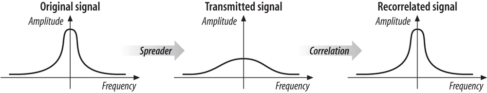
At the left is a traditional narrowband radio signal. It is processed by a spreader, which applies a mathematical transform to take a narrowband input and flatten the amplitude across a relatively wide frequency band. To a narrowband receiver, the transmitted gnal looks like low-level noise because its RF energy is spread across a very wide band. The key to direct-sequence transmission is that any modulation of the RF carrier is also spread across the frequency band. Receivers can monitor a wide frequency band and look for changes that occur across the entire band. The original signal can be recovered with a correlator, which inverts the spreading process.
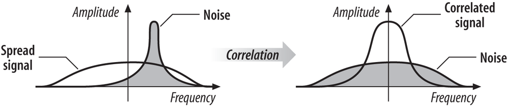
At a high level, a correlator simply looks for changes to the RF signal that occur across the entire frequency band. Correlation gives direct-sequence transmissions a great deal of protection against interference. Noise tends to take the form of relatively narrow pulses that, by definition, do not produce coherent effects across the entire frequency band. Therefore, the correlation function spreads out noise across the band, and the correlated signal shines through, as illustrated in Figure 12-2.
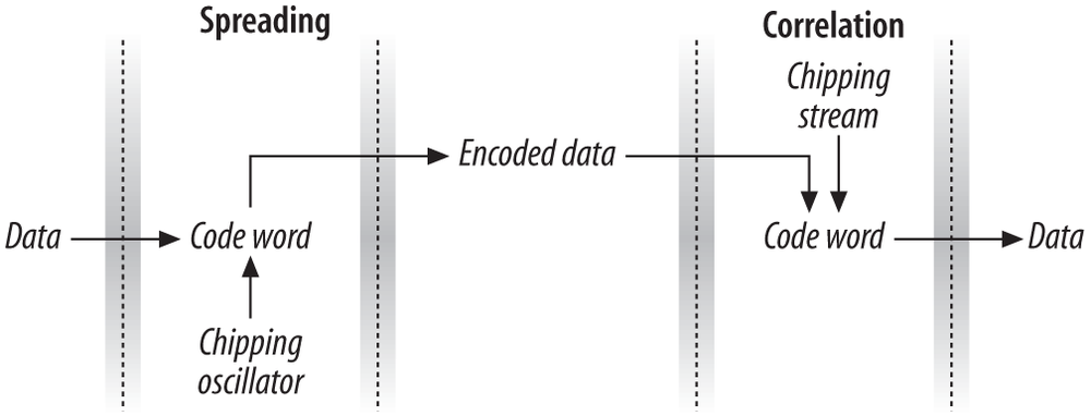
Direct-sequence modulation works by applying a chipping sequence to the data stream. A chip is a binary digit used by the spreading process. Bits are higher-level data, while chips are binary numbers used in the encoding process. There is no mathematical difference between a bit and a chip, but spread-spectrum developers have adopted this terminology to indicate that chips are only a part of the encoding and transmission process and do not carry any data. Chipping streams, which are also called pseudorandom noise codes (PN codes), must run at a much higher rate than the underlying data. (The requirement for high-speed oscillators to generate chip streams and recover data from chip streams is one of the major power drains in direct sequence PHYs.) Figure 12-3 illustrates how chipping sequences are used in the transmission of data using direct-sequence modulation. At the left-hand side is a single data bit, which is either a one or a zero. For each data bit, several chips are used. In the figure, the chip stream consists of an 11-bit code. It is combined with the single data bit, to produce 11 chips that carry the single data bit. The 11-chip/single-data-bit sequence is transmitted over the radio link and received at the other end. Every chunk of 11 chips is then compared to an identical chip stream. If it matches the spreading code, a single zero data bit is recovered; if not, a single one data bit is recovered.
The process of encoding a low bit-rate signal at a high chip rate has the side effect of spreading the signal’s power over a much wider bandwidth. One of the most important quantities in a direct-sequence system is its spreading ratio, which is the number of chips used to transmit a single bit.[55] Higher spreading ratios improve the ability to recover the transmitted signal but require a higher chipping rate and a larger frequency band. Doubling the spreading ratio requires doubling the chipping rate and doubles the required bandwidth as well. There are two costs to increased chipping ratios. One is the direct cost of more expensive RF components operating at the higher frequency, and the other is an indirect cost in the amount of bandwidth required. Therefore, in designing direct-sequence systems for the real world, the spreading ratio should be as low as possible to meet design requirements and to avoid wasting bandwidth.
Direct-sequence modulation trades bandwidth for throughput. Compared to traditional narrowband transmission, direct-sequence modulation requires significantly more radio spectrum and is much slower. However, it can often coexist with other interference sources because the receiver’s correlation function effectively ignores narrowband noise. It is easier to achieve high throughput using direct-sequence techniques than with frequency hopping. Regulatory authorities do not impose a limit on the amount of spectrum that can be used; they generally set a minimum lower bound on the processing gain. Higher rates can be achieved with a wider band, though wider bands require a higher chip rate.
Encoding in 802.11 Direct Sequence Networks
For the PN code, 802.11 adopted an 11-bit Barker word. Each bit is encoded using the entire Barker word as a chipping sequence. Detailed discussion of Barker words and their properties are well beyond the scope of this book. The key attribute for 802.11 networks is that Barker words have good autocorrelation properties, which means that the correlation function at the receiver operates as expected in a wide range of environments and is relatively tolerant to multipath delay spreads. 11 bits are in the word because regulatory authorities often require a 10-dB processing gain in direct sequence systems. Using an 11-bit spreading code for each bit allows 802.11 to meet the regulatory requirements with some margin of safety, but it is small enough to allow as many overlapping networks as possible. Longer spreading codes allow higher processing gains but require wider frequency channels.
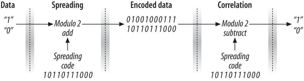
802.11 uses the Barker sequence {+1, -1, +1, +1, -1, +1, +1, +1, -1, -1, -1}. As used in 802.11, +1 becomes 1, and -1 becomes 0, so the Barker sequence becomes 10110111000. It is applied to each bit in the data stream by a modulo-2 adder.[56] When a 1 is encoded, all the bits in the spreading code change; for 0, they stay the same. Figure 12-4 shows the encoding process.
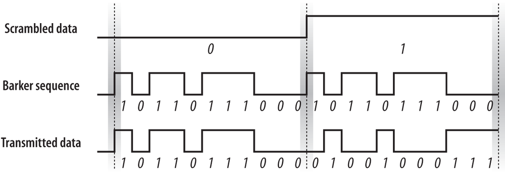
Receivers can look at the number of 1s in a received bit time. The Barker sequence has six 1s and five 0s. An 11-bit sequence with six 1s must therefore correspond to a transmitted 0, and an 11-bit sequence with six 0s must correspond to a transmitted 1. In addition to counting the numbers of 1s and 0s, the receiver can analyze the pattern of received bits to infer the value of the transmitted bit.
Radio Spectrum Usage in 802.11 Direct Sequence Networks
Channels for the DS PHY are much larger than the channels for the FH PHY. The DS PHY has 14 channels in the 2.4-GHz band, each 5 MHz wide. Channel 1 is placed at 2.412 GHz, channel 2 at 2.417 GHz, and so on up to channel 13 at 2.472 GHz. Channel 14 was defined especially for operation in Japan, and has a center frequency that is 12 MHz from the center frequency of channel 13. Table 12-1 shows which channels are allowed by each regulatory authority. Channel 10 is available throughout North America and Europe, which is why many products use channel 10 as the default operating channel.
Regulatory domain | Allowed channels |
U.S. (FCC)/Canada (IC) | 1 to 11 (2.412-2.462 GHz) |
Europe, excluding Spain (ETSI) | 1 to 13 (2.412-2.472 GHz) |
Spain | 10 to 11 (2.457-2.462 GHz) |
Japan (MIC) | 1 to 13 (2.412-2.462 GHz) and 14 (2.484 GHz) |
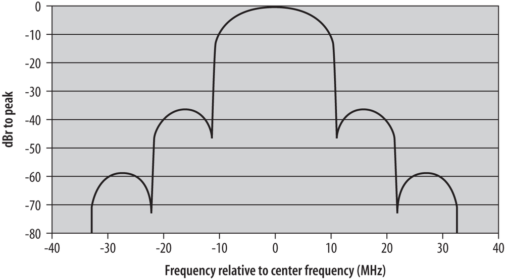
Channel energy spread
Within a channel, most of the energy is spread across a 22-MHz band. Because the DS PHY uses an 11-MHz chip clock, energy spreads out from the channel center in multiples of 11 MHz, as shown in Figure 12-5. To prevent interference to adjacent channels, the first side lobe is filtered to 30 dB below the power at the channel center frequency, and additional lobes are filtered to 50 dB below the power at the channel center. This corresponds to reducing the power by a factor of 1,000 and 100,000, respectively. These limits are noted in Figure 12-5 by the use of dBr, which means dB relative to the power at the channel center. Figure 12-5 uses a logarithmic scale: -30 dBr is only one thousandth, and -50 dBr is one hundred thousandth.
With the transmit filters in place, RF power is confined mostly to 22-MHz frequency bands. European regulators cap the maximum radiated power at 100 mW; the FCC in the U.S. allows a substantially higher transmission power of 1,000 mW. If directional antennas are used, the power can be concentrated into an even higher radiated power.
Adjacent channel rejection and channel separation
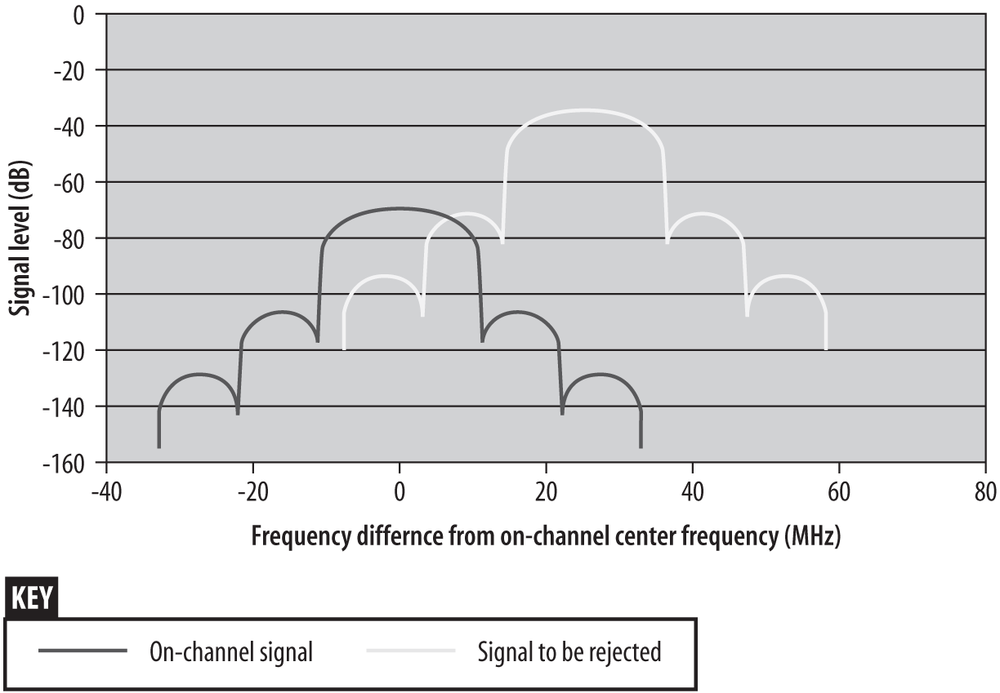
To avoid interference, 802.11 equipment must be separated in the frequency domain. The initial specification called for 35 dB rejection when two signals were 30 MHz apart, but the spectral separation was tightened up to 25 MHz in 802.11b. To measure adjacent channel rejection, input a maximum-speed signal at the center frequency of a channel, shown by the left curve in Figure 12-6. Its power is 6 dB above the specified minimum sensitivity; for an 802.11b receiver, that is -70 dBm. A second 802.11b signal at 11 Mbps is sent in, 35 dB stronger, but at least 25 MHz away. The right curve depicts the interference test signal. As long as the frame error rate is less than 8%, the receiver passes the test. Note that there is reasonably significant overlap between the first lobe of the interfering signal and the main center lobe of the on-channel signal.
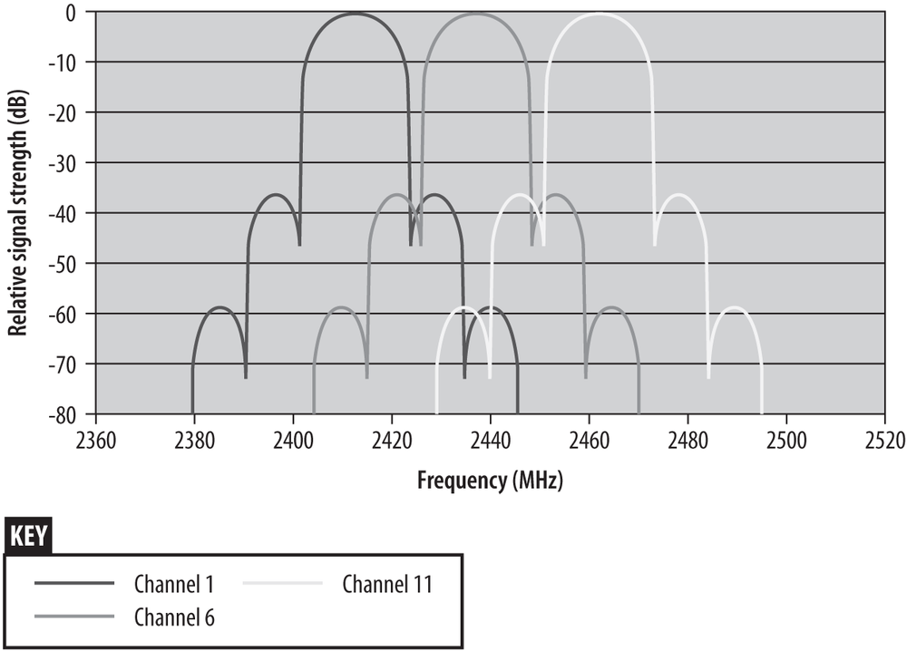
Adjacent channel rejection also influences the number of channels that can be used simultaneously. Although 802.11 networks operating in the ISM band have 14 defined channels, they are closely packed. Real signals must be spaced out to prevent interference. 802.11b specifies that a 25 MHz (5 channel number) spacing is sufficient. Figure 12-7 shows the spectral mask of transmissions on the so-called non-overlapping channels (1, 6, and 11). By comparing Figure 12-7 to the previous figure, it is easy to see that using the nonoverlapping channel set requires all components in the system to run at maximum effectiveness. Many real-world radios, however, are incapable of rejecting strong adjacent-channel transmissions near the limit.
Although it is possible to have channels overlap more closely by using a four-channel layout (say, 1, 4, 7, and 11), it is not a generally useful deployment strategy. Greater overlap of the channels will result in more interference between radios operating on adjacent frequencies. Greater interference may trigger the carrier sensing mechanisms to report that the medium is busy or cause frames to be mangled in flight. In either case, the peak throughput of each channel is less. It may be that trading some amount of peak throughput for total area capacity is a good trade, but that is not generally true.
Maximum theoretical throughput
If the signal processing techniques used by the DS PHY are used, then the maximum throughput would be a function of the frequency space used. Roughly speaking, the ISM band is 80-MHz wide. Using the same spreading factor of 11 would lead to a maximum bit rate of slightly more than 7 Mbps. However, only one channel would be available, and products would need to have an oscillator running at 77 MHz to generate the chipping sequence. High-frequency devices are a tremendous drain on batteries, and the hypothetical high-rate encoding that uses the entire band makes terrible use of the available spectrum. To achieve higher throughput, more sophisticated techniques must be used. 802.11b increases the symbol rate slightly, but it gets far more mileage from more sophisticated encoding techniques.
Interference response
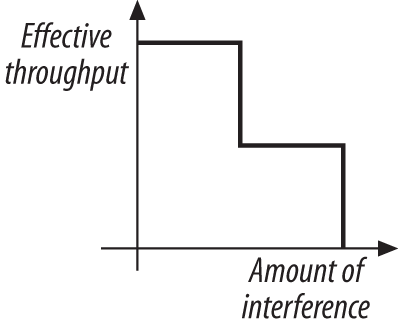
Direct-sequence-modulated signals are more resistant to interference than frequency-hopping signals. The correlation process enables direct-sequence systems to work around narrowband interference much more effectively. With 11 chips per bit, several chips can be lost or damaged before a single data bit is lost. The disadvantage is that the response of direct-sequence systems to noise is not incremental. Up to a certain level, the correlator can remove noise, but once interference obscures a certain amount of the frequency band, nothing can be recovered. Figure 12-8 shows how direct-sequence systems degrade in response to noise.
Direct-sequence systems also avoid interfering with a primary user more effectively than frequency-hopping systems. After direct-sequence processing, signals are much wider and have lower amplitudes, so they appear to be random background noise to traditional narrowband receivers. Two direct-sequence users in the same area can cause problems for each other quite easily if the two direct-sequence channels are not separated by an adequate amount. Generally speaking, interference between two direct-sequence devices is a problem long before a primary band user notices anything.
Differential Phase Shift Keying (DPSK)
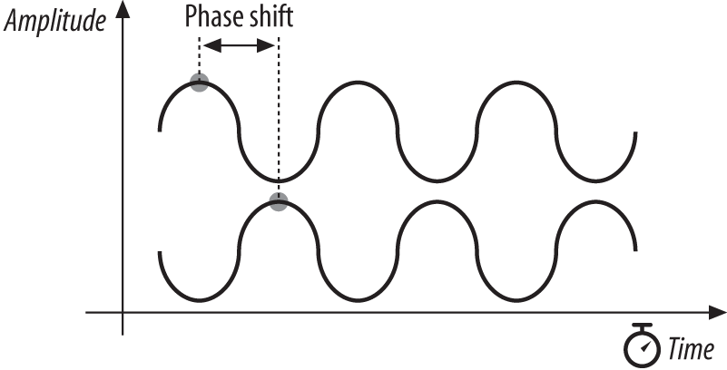
Differential phase shift keying (DPSK) is the basis for 802.11 direct-sequence systems. As the name implies, phase shift keying (PSK) encodes data in phase changes of the transmitted signal. The absolute phase of a waveform is not relevant in PSK; only changes in the phase encode data. Like frequency shift keying, PSK resists interference because most interference causes changes in amplitude. Figure 12-9 shows two identical sine waves shifted by a small amount along the time axis. The offset between the same point on two waves is the phase difference.
Differential Binary Phase Shift Keying (DBPSK)
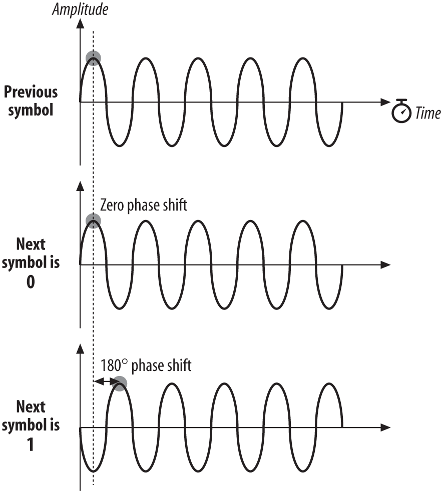
The simplest form of PSK uses two carrier waves, shifted by a half cycle relative to each other. One wave, the reference wave, is used to encode a 0; the half-cycle shifted wave is used to encode a 1. Table 12-2 summarizes the phase shifts.
Figure 12-10 illustrates the encoding as a phase difference from a preceding sine wave.
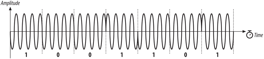
To stick with the same example, encoding the letter M (1001101 in binary) is a matter of dividing up the time into seven symbol times then transmitting the wave with appropriate phase shift at each symbol boundary. Figure 12-11 illustrates the encoding. Time is divided into a series of symbol periods, each of which is several times the period of the carrier wave. When the symbol is a 0, there is no change from the phase of the previous symbol, and when the symbol is a 1, there is a change of half a cycle. These changes result in “pinches” of the carrier when 1 is transmitted and a smooth transition across the symbol time boundary for 0.
Differential Quadrature Phase Shift Keying (DQPSK)
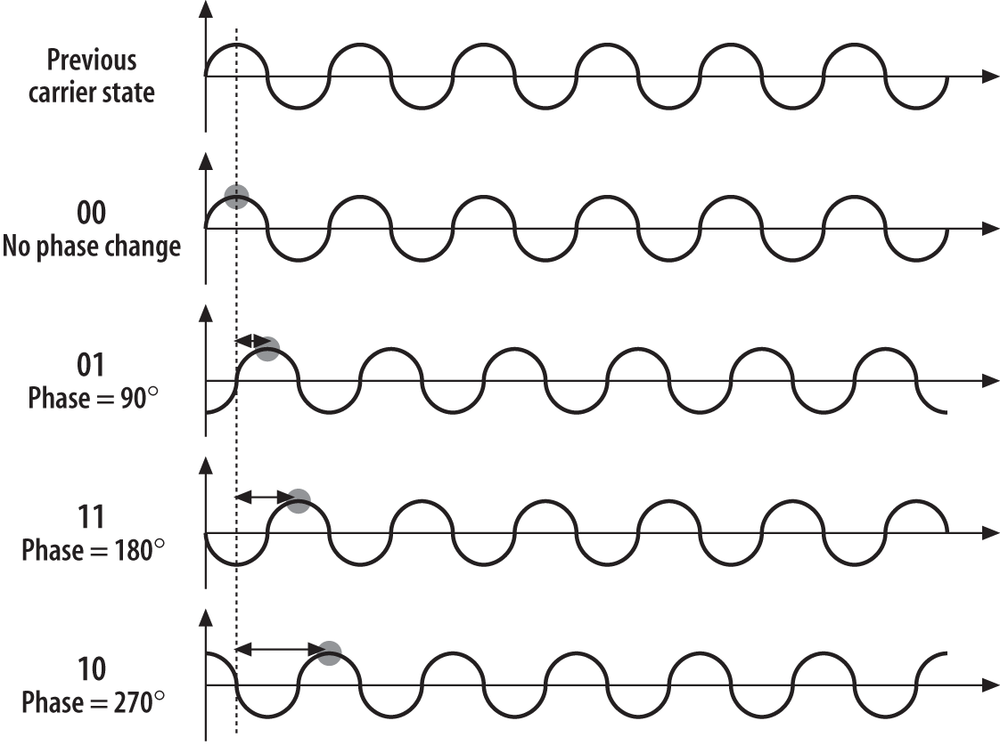
Like 2GFSK, DBPSK is limited to one bit per symbol. More advanced receivers and transmitters can encode multiple bits per symbol using a technique called differential quadrature phase shift keying (DQPSK). Rather than a fundamental wave and a half-cycle shifted wave, DQPSK uses a fundamental wave and three additional waves, each shifted by a quarter cycle, as shown in Figure 12-12. Table 12-3 summarizes the phase shifts.
Symbol | Phase shift |
00 | 0 |
01 | 90° (π/2 radians) |
11 | 180° (π radians) |
10 | 270° (3π/2 or -π/2 radians) |
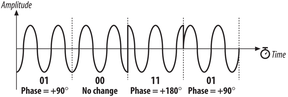
Now encode M in DQPSK (Figure 12-13). In the UTF-8 character set, M is represented by the binary string 01001101 or, as the sequence of four two-bit symbols, 01-00-11-01. In the first symbol period, there is a phase shift of 90 degrees; for clarity, the figure shows the phase shift from a pure sine wave. The second symbol results in no phase shift, so the wave continues without a change. The third symbol causes a phase shift of 180 degrees, as shown by the sharp change from the highest amplitude to the lowest amplitude. The final symbol causes a phase shift of 90 degrees.
The obvious advantage of DQPSK relative to DBPSK is that the four-level encoding mechanism can have a higher throughput. The cost of using DQPSK is that it cannot be used in some environments because of severe multipath interference. Multipath interference occurs when the signal takes several paths from the transmitter to the receiver. Each path has a different length; therefore, the received signal from each path has a different delay relative to the other paths. This delay is the enemy of an encoding scheme based on phase shifts. Wavefronts are not labeled or painted different colors, so a wavefront could arrive later than expected because of a long path or it could simply have been transmitted late and phase-shifted. In environments where multipath interference is severe, DQPSK will break down much quicker than DBPSK.
The “Original” Direct Sequence PHY
The physical layer itself consists of two components. The Physical Layer Convergence Procedure (PLCP) performs some additional PHY-dependent framing before transmission, while the Physical Medium Dependent (PMD) layer is responsible for the actual transmission of frames.
PLCP Framing and Processing
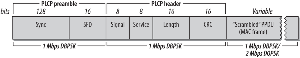
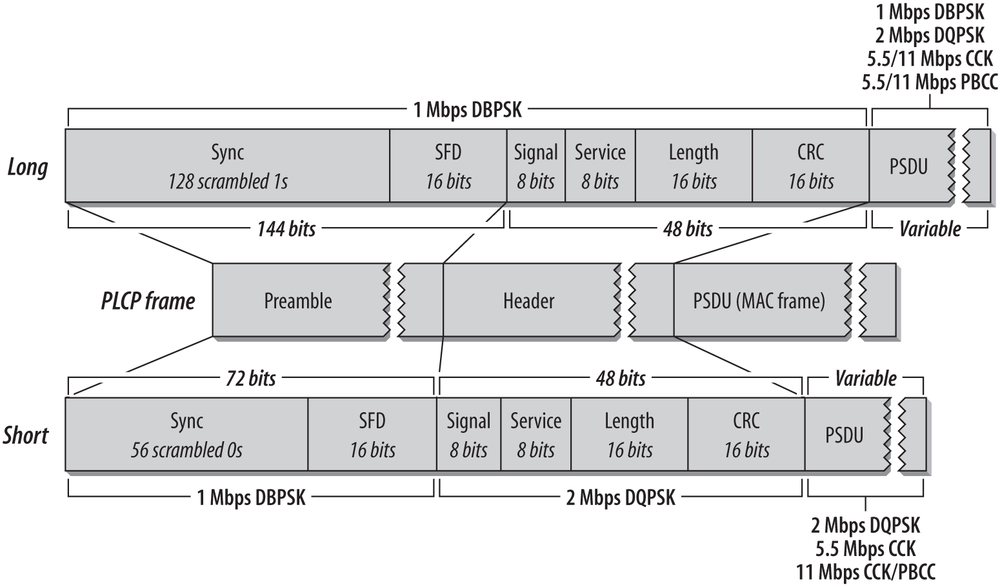
The PLCP for the DS PHY adds a six-field header to the frames it receives from the MAC. In keeping with ISO reference model terminology, frames passed from the MAC are PLCP service data units (PSDUs). The PLCP framing is shown in Figure 12-14.
The FH PHY uses a data whitener to randomize the data before transmission, but the data whitener applies only to the MAC frame trailing the PLCP header. The DS PHY has a similar function called the scrambler, but the scrambler is applied to the entirety of the direct-sequence frame, including the PLCP header and preamble.
- Preamble
The Preamble synchronizes the transmitter and receiver and allows them to derive common timing relationships. It is composed of the Sync field and the Start Frame Delimiter field. Before transmission, the preamble is scrambled using the direct-sequence scrambling function.
- Sync
The Sync field is a 128-bit field composed entirely of 1s. Unlike the FH PHY, the Sync field is scrambled before transmission.
- Start Frame Delimiter (SFD)
The SFD allows the receiver to find the start of the frame, even if some of the sync bits were lost in transit. This field is set to 0000 0101 1100 1111, which is different from the SFD used by the FH PHY.
- Header
The PLCP header follows the preamble. The header has PHY-specific parameters used by the PLCP. Four fields comprise the header: a signaling field, a service identification field, a Length field, a Signal field used to encode the speed, and a frame-check sequence.
- Signal
The Signal field is used by the receiver to identify the transmission rate of the encapsulated MAC frame. It is set to either 0000 1010 (0x0A) for 1-Mbps operation or 0001 0100 (0x14) for 2-Mbps operation.
- Service
This field is reserved for future use and must be set to all 0s.
- Length
This field is set to the number of microseconds required to transmit the frame as an unsigned 16-bit integer, transmitted least-significant bit to most-significant bit.
- CRC
To protect the header against corruption on the radio link, the sender calculates a 16-bit CRC over the contents of the four header fields. Receivers verify the CRC before further frame processing.
No restrictions are placed on the content of the Data field. Arbitrary data may contain long strings of consecutive 0s or 1s, which makes the data much less random. To make the data more like random background noise, the DS PHY uses a polynomial scrambling mechanism to remove long strings of 1s or 0s from the transmitted data stream.
DS Physical Medium Dependent Sublayer
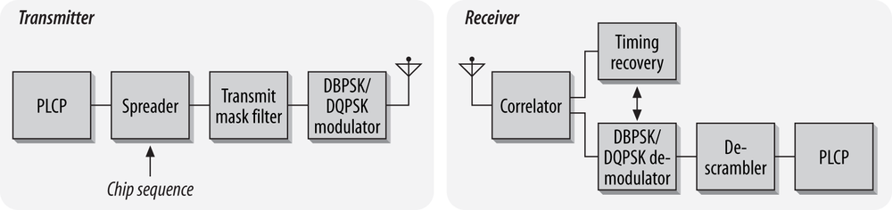
The PMD is a complex and lengthy specification that incorporates provisions for two data rates (1.0 and 2.0 Mbps). Figure 12-15 shows the general design of a transceiver for 802.11 direct-sequence networks.
Transmission at 1.0 Mbps
At the low data rate, the direct-sequence PMD enables data transmission at 1.0 Mbps. The PLCP header is appended to frames arriving from the MAC, and the entire unit is scrambled. The resulting sequence of bits is transmitted from the physical interface using DBPSK at a rate of 1 million symbols per second. The resulting throughput is 1.0 Mbps because one bit is encoded per symbol. Like the FH PMD, the DS PMD has a minimum power requirement and can cap the power at 100 mW if necessary to meet regulatory requirements.
Transmission at 2.0 Mbps
Like the FH PHY, transmission at 2.0 Mbps uses two encoding schemes. The PLCP preamble and header are transmitted at 1.0 Mbps using DBPSK. Although using a slower method for the header transmission reduces the effective throughput, DBPSK is far more tolerant of noise and multipath interference. After the preamble and header are finished, the PMD switches to DQPSK modulation to provide 2.0-Mbps service. As with the FH PHY, most products that implement the 2.0-Mbps rate can detect interference and fall back to lower-speed 1.0-Mbps service.
CS/CCA for the DS PHY
802.11 allows the carrier sense/clear channel assessment function to operate in one of three modes:
- Mode 1
When the energy exceeds the energy detection (ED) threshold, it reports that the medium is busy. The ED threshold depends on the transmit power.
- Mode 2
Implementations using Mode 2 must look for an actual DSSS signal and report the channel busy when one is detected, even if the signal is below the ED threshold.
- Mode 3
Mode 3 combines Mode 1 and Mode 2. A signal must be detected with sufficient energy before the channel is reported busy to higher layers.
Once a channel is reported busy, it stays busy for the duration of the intended transmission, even if the signal is lost. The transmission’s duration is taken from the time interval in the Length field. Busy medium reports must be very fast. When a signal is detected at the beginning of a contention window slot, the CCA mechanism must report a busy medium by the time the slot has ended. This relatively high performance requirement must be set because once a station has begun transmission at the end of its contention delay, it should seize the medium, and all other stations should defer access until its frame has concluded.
Characteristics of the DS PHY
Table 12-4 shows the values of a number of parameters in the DS PHY. In addition to the parameters in the table, which are standardized, the DS PHY has a number of parameters that can be adjusted to balance delays through various parts of an 802.11 direct-sequence system. It includes variables for the latency through the MAC, the PLCP, and the transceiver, as well as variables to account for variations in the transceiver electronics. One other item of note is that the total aggregate throughput of all direct-sequence networks in an area is much lower than the total aggregate throughput of all nonoverlapping frequency-hopping networks in an area. The total aggregate throughput is a function of the number of nonoverlapping channels. In North America and most of Europe, three direct-sequence networks can be deployed in an area at once. If each network is run at the optional 2 Mbps rate and the efficiency of the protocol allows 50% of the headline rate to become user data throughput, the total throughput is 3 Mbps, which is dramatically less than the frequency-hopping total aggregate throughput.
Parameter | Value | Notes |
Slot time | 20 μs | |
SIFS time | 10 μs | The SIFS is used to derive the value of the other interframe spaces (DIFS, PIFS, and EIFS). |
Contention window size | 31 to 1,023 slots | |
Preamble duration | 144 μs | Preamble symbols are transmitted at 1 MHz, so a symbol takes 1 μs to transmit; 144 bits require 144 symbol times. |
PLCP header duration | 48 μs | The PLCP header is 48 bits, so it requires 48 symbol times. |
Maximum MAC frame | 4-8,191 bytes | |
Minimum receiver sensitivity | -80 dBm | |
Adjacent channel rejection | 35 dB | See text for measurement details. |
Like the FH PHY, the DS PHY has a number of attributes that can be adjusted by a vendor to balance delays in various parts of the system. It includes variables for the latency through the MAC, the PLCP, and the transceiver, as well as variables to account for variations in the transceiver electronics.
Complementary Code Keying
802.11 direct-sequence systems use a rate of 11 million chips per second. The original DS PHYs divided the chip stream up into a series of 11-bit Barker words and transmitted 1 million Barker words per second. Each word encoded either one bit or two bits for a corresponding data rate of 1.0 Mbps or 2.0 Mbps, respectively. Achieving higher data rates and commercial utility requires that each code symbol carry more information than a bit or two.
Straight phase shift encoding cannot hope to carry more than a few bits per code word. DQPSK requires that receivers distinguish quarter-cycle phase differences. Further increasing the number of bits per symbol would require processing even finer phase shifts, such as an eighth-cycle or sixteenth-cycle shift. Detecting smaller phase shifts is more difficult in the presence of multipath interference and requires more sophisticated (and thus expensive) electronics.
Instead of continuing with straight phase-shift keying, the IEEE 802.11 working group turned to an alternate encoding method. Complementary code keying (CCK) divides the chip stream into a series of 8-bit code symbols, so the underlying transmission is based on a series of 1.375 million code symbols per second. CCK is based on sophisticated mathematical transforms that allow the use of a few 8-bit sequences to encode 4 or even 8 bits per code word, for a data throughput of 5.5 Mbps or 11 Mbps. In addition, the mathematics underlying CCK transforms allow receivers to distinguish between different codes easily, even in the presence of interference and multipath fading. Figure 12-16 illustrates the use of code symbols in CCK. It is quite similar to the chipping process used by the slower direct-sequence layers; the difference is that the code words are derived partially from the data. A static repeating code word such as the Barker word is not used.
Barker spreading, as used in the lower-rate, direct-sequence layers, uses a static code to spread the signal over the available frequency band. CCK uses the code word to carry information, as well as simply to spread the signal. Several phase angles are used to prepare a complex code word of eight bits.
High Rate Direct Sequence PHY
To distinguish it from the original direct sequence PHY, the high rate PHY that runs at 11 Mbps is abbreviated as HR/DSSS. Like its predecessor, it is split into a convergence procedure that prepares frames for radio transmission, and a medium-dependent layer that turns the bits into radio waves in the air.
PLCP Framing and Scrambling
The long headers required by the original PHY greatly reduce performance. The 802.11 MAC requires an acknowledgment for every data frame, and the 192 microsecond preamble is much, much longer than the MAC acknowledgment. At the 11 Mbps data rate, the preamble and PLCP framing header sucks up 25% of the time used to transmit a 1,500 byte frame and its corresponding MAC acknowledgment. As long as a new PHY was being developed, the designers of 802.11b came up with a new “short” framing format that improves protocol efficiency and, hence, throughput. Using the short headers cuts the preamble and PLCP framing overhead cuts the preamble and framing overhead to 14%. While still substantial, it is a dramatic improvement. Figure 12-17 shows the PLCP framing specified in 802.11b. When 802.11b was first released, short headers were not supported by all devices because of the large installed base of 2 Mbps direct sequence equipment. At this point, almost every card can safely support the short preamble, and most access point vendors use it by default.
Naturally, the optional short format may be used only if all stations support it. To prevent networks configured for the short format from disappearing, 802.11b requires that stations answering Probe Requests from an active scan return a response using the same PLCP header that was received. If a station that supports only the long PLCP header sends a Probe Response, an access point returns a response using the long header, even if the BSS is configured for the short header.
- Preamble
Frames begin with the preamble, which is composed of the Sync field and the SFD field. The preamble is transmitted at 1.0 Mbps using DBPSK.
- Long Sync
The Long Sync field is composed of 128 one bits. It is processed by the scrambler before transmission, though, so the data content varies. High-rate systems use a specified seed for the scrambling function but support backwards compatibility with older systems that do not specify a seed.
- Short Sync
The Short Sync field is composed of 56 zero bits. Like the Long Sync, it is also processed by the scrambler.
- Long SFD
To indicate the end of the Sync field, the long preamble concludes with a Start of Frame Delimiter (SFD). In the long PLCP, the SFD is the sequence 1111 0011 1010 0000. As with all IEEE specifications, the order of transmission from the physical interface is least-significant bit first, so the string is transmitted right to left.
- Short SFD
To avoid confusion with the Long SFD, the Short SFD is the reverse value, 0000 0101 1100 1111.
The PLCP header follows the preamble. It is composed of the Signal, Service, Length, and CRC fields. The long header is transmitted at 1.0 Mbps using DBPSK. However, the short header’s purpose is to reduce the time required for overhead transmission so it is transmitted at 2.0 Mbps using DQPSK.
- Long Signal
The Long Signal field indicates the speed and transmission method of the enclosed MAC frame. Four values for the 8-bit code are currently defined and are shown in Table 12-5.
- Short Signal
The Short Signal field indicates the speed and transmission method of the enclosed frame, but only three values are defined. Short preambles can be used only with 2 Mbps, 5.5 Mbps, and 11 Mbps networks.
- Service
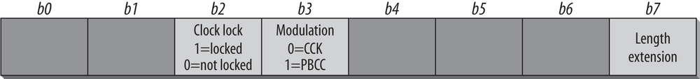
The Service field, which is shown in Figure 12-18, was reserved for future use by the first version of 802.11, and bits were promptly used for the high-rate extensions in 802.11b. First of all, the Length field describes the amount of time used for the enclosed frame in microseconds. Above 8 Mbps, the value becomes ambiguous. Therefore, the eighth bit of the service field is used to extend the Length field to 17 bits. The third bit indicates whether the 802.11b implementation uses locked clocks; clock locking means that transmit frequency and symbol clock use the same oscillator. The fourth bit indicates the type of coding used for the packet, which is either 0 for CCK or 1 for PBCC. All reserved bits must be set to 0. The Service field is transmitted from left to right (b0 to b7), which is the same in both the short and long PLCP frame formats. (Further changes are made by 802.11g, which will be discussed in Chapter 14.)
- Length
The Length field is the same in both the short and long PLCP frame formats and is the number of microseconds required to transmit the enclosed MAC frame. Approximately two pages of the 802.11b standard are devoted to calculating the value of the Length frame, but the details are beyond the scope of this book.
- CRC
The CRC field is the same in both the short and the long PLCP frames. Senders calculate a CRC checksum using the Signal, Service, and Length fields. Receivers can use the CRC value to ensure that the header was received intact and was not damaged during transmission. CRC calculations take place before data scrambling.
The data scrambling procedure for the HR/DSSS PHY is nearly identical to the data scrambling procedure used with the original DS PHY. The only difference is that the scrambling function is seeded to specified values in the HR/DSSS PHY. Different seeds are used for short and long PLCP frames.
HR/DSSS PMD
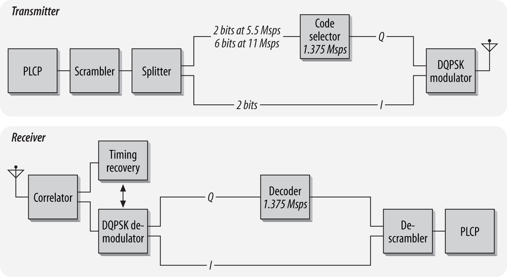
Like the DS PHY, the 802.11b PHY uses a single PMD specification. The general transceiver design is shown in Figure 12-19.
Transmission at 1.0 Mbps or 2.0 Mbps
To ensure backwards compatibility with the installed base of 802.11-based, direct-sequence hardware, the HR/DSSS PHY can transmit and receive at 1.0 Mbps or 2.0 Mbps. Slower transmissions are supported in the same manner as the lower-rate, direct-sequence layers described in previously in this chapter. Any transmissions at the slower rates must use long headers.
Transmission at 5.5 Mbps with CCK
Higher-rate transmission is accomplished by building on the DQPSK-based phase shift keying techniques. DQPSK transmits two bits per symbol period, encoded as one of four different phase shifts. By using CCK, the symbol words themselves carry additional information. 5.5-Mbps transmission encodes four data bits into a symbol. Two bits are carried using conventional DQPSK, and the other two are carried through the content of the code words. Figure 12-20 illustrates the overall process.
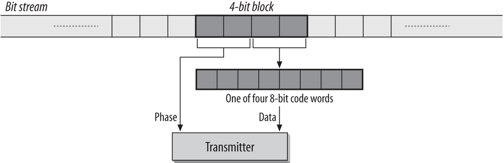
The MAC frame embedded in the PLCP frame is divided into a string of 4-bit blocks. Each 4-bit block is further divided into two 2-bit segments.
The first 2-bit segment is encoded by means of a DQPSK-type phase shift between the current symbol and the previous symbol (Table 12-6). Even and odd symbols use a different phase shift for technical reasons. Symbol numbering starts with 0 for the first 4- bit block.
The second 2-bit segment is used to select one of four code words for the current symbol (Table 12-7). The four code words can be derived using the mathematics laid out in clause 18.4.6.5 of the 802.11 standard.
Transmission at 11 Mbps with CCK
To move to a full 11 Mbps, 8 bits must be encoded with each symbol. As with other techniques, the first two bits are encoded by the phase shift of the transmitted symbol relative to the previous symbol. Six bits are encoded using CCK. Figure 12-21 illustrates the process.
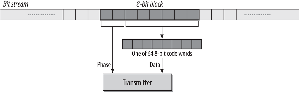
The MAC frame embedded in the PLCP frame is divided into a string of 8-bit blocks. Each 8-bit block is further divided into four 2-bit segments.
The first 2-bit segment is encoded by means of a DQPSK-type phase shift between the current symbol and the previous symbol. As with the 5.5-Mbps rate, even and odd symbols use a different phase shift for technical reasons. Symbol numbering starts with 0 for the first 8-bit block. The phase shifts are identical to the phase shifts used in 5.5-Mbps transmission.
The remaining six bits are grouped into three successive pairs. Each pair is associated with the phase angle in Table 12-8 and is used to derive a code word.
As an example, consider the conversion of the bit sequence 0100 1101 into a complex code for transmission on an 802.11b network. The first two bits, 01, encode a phase shift from the previous symbol. If the symbol is an even symbol in the MAC frame, the phase shift is π/2; otherwise, the shift is 3π/2. (Symbols in the MAC frame are numbered starting from 0, so the first symbol in a frame is even.) The last six bits are divided into three 2-bit groups: 00, 11, and 01. Each of these is used to encode an angle in the code word equation. The next step in transmission is to convert the phase angles into the complex code word for transmission.
Clear channel assessment
Like the original DS PHY, high-rate implementers have three choices for the CS/CCA operation mode. All the direct-sequence CCA modes are considered to be part of the same list. Mode 1 is identical to the DS PHY’s CCA Mode 1, and Modes 2 and 3 are used exclusively by the original DS PHY. Modes 4 and 5 are the HR/DSSS-specific CCA modes.
- Mode 1
When the energy exceeds the energy detection (ED) threshold, the medium is reported busy. The ED threshold depends on the transmit power used. This mode is also available for classic direct-sequence systems.
- Mode 4
Implementations using Mode 4 look for an actual signal. When triggered, a Mode 4 CCA implementation starts a 3.65 ms timer and begins counting down. If no valid HR/DSSS signal is received by the expiration of the timer, the medium is reported idle. 3.65 ms corresponds to the transmission time required for the largest possible frame at 5.5 Mbps.
- Mode 5
Mode 5 combines Mode 1 and Mode 4. A signal must be detected with sufficient energy before the channel is reported busy to higher layers.
Once a channel is reported busy, it stays busy for the duration of the intended transmission, even if the signal is lost. The channel is considered busy until the time interval in the Length field has elapsed. Implementations that look for a valid signal may override this requirement if a second PLCP header is detected.
Optional Features of the 802.11b PHY
802.11b includes two optional physical-layer features, neither of which is widely used. Packet Binary Convolutional Coding (PBCC) was proposed as a method of reaching the 11 Mbps data rate, but it was never widely implemented. Proposals for further revisions to wireless LAN technology in the ISM band specified PBCC, but those proposals were rejected in the summer of 2001.
A second optional feature, channel agility, was designed to assist networks in avoiding interference. Channel agility causes the center channel to shift periodically in the hope that interference can be avoided. Channel agility was never widely used because it was not particularly helpful. In the presence of interference, some throughput would be recovered as receivers hopped to another channel, but the additional spectrum required made it much more effective to hunt down and fix the interference, or remap channels around it.
Characteristics of the HR/DSSS PHY
Table 12-9shows the values of a number of parameters in the HR/DSSS PHY. Like the DS PHY, the HR/DSSS PHY has a number of parameters that can be adjusted to compensate for delays in any part of a real system.
Parameter | Value | Notes |
Maximum MAC frame length | 4,095 bytes | |
Slot time | 20 μs | |
SIFS time | 10 μs | The SIFS is used to derive the value of the other interframe spaces (DIFS, PIFS, and EIFS). |
Contention window size | 31 to 1,023 slots | |
Preamble duration | 144 μs | Preamble symbols are transmitted at 1 MHz, so a symbol takes 1 μs to transmit; 96 bits require 96 symbol times. |
PLCP header duration | 48 bits | The PLCP header transmission time depends on whether the short preamble is used. |
Minimum sensitivity | -76 dBm | |
Adjacent channel rejection | 35 dB | See text for measurement notes. |
One other item of note is that the total aggregate throughput of all HR/DSSS networks in an area is still lower than the total aggregate throughput of all nonoverlapping frequency-hopping networks in an area. The total aggregate throughput is a function of the number of nonoverlapping channels. In North America and most of Europe, three HR/DSSS networks can be deployed in an area at once. Running each network at the top speed of 11 Mbps, and assuming user payload data throughput of 50%, the total aggregate throughput will be 16.5 Mbps.
[55] The spreading ratio is related to a figure known as the processing gain. The two are sometimes used interchangeably, but the processing gain is slightly lower because it takes into account the effects of using real-world systems as opposed to perfect ideal systems with no losses.
[56] Encoding with the Barker sequence is similar to a number of other techniques. Some cellular systems, most notably in North America, use code division multiple access (CDMA) to allow several stations to access the radio medium. CDMA exploits some extremely complex mathematics to ensure that transmissions from each mobile phone look like random noise to every other mobile phone in the cell. The underlying mathematics are far more complicated than a simple, fixed pseudorandom noise code.