Chapter Two. Using the Drawing Tools
Before the introduction of Flash, most popular graphics programs were designed to create and edit bitmapped graphics. A bitmapped graphic (also known as a raster graphic or simply a bitmap) is made up of small squares called pixels.
Flash was one of the first popular programs to rely primarily on vector graphics instead of bitmaps. Vector graphics are essentially mathematical formulas that tell the computer what to draw. One of the innovations in Flash was a new set of tools that made creating vector graphics as simple and intuitive as creating bitmapped graphics.
Since then, other programs such as Adobe Illustrator have also simplified the process of making vector graphics, but the implementation of vector drawing in Flash is different from that in other programs. To work in Flash, you need to be familiar with the idiosyncratic way that Flash handles vector graphics.
Getting Familiar with Paths
The most basic element of a vector drawing is a path, a series of anchor points connected by either straight lines or curves. Think of the anchor points as a skeleton that gives a path its structure, and think of the connecting lines or curves as skin stretched over the skeleton.
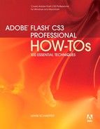
Paths can be open or closed. An open path has a beginning and end, marked by anchor points known as endpoints. A closed path completely encloses an area; it has no beginning and no end (Figure 7a). You create paths using drawing tools such as the Pen, the Pencil, and the Brush, all of which you’ll learn about later in this chapter.
Figure 7a. On the left is an open path; on the right is a closed path. Anchor points are represented in Flash by small squares.
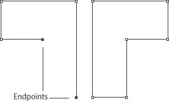
To do anything to an existing path—such as edit, move, or delete it—you must tell Flash which path or paths you want to work with by selecting it with a tool. The two most important such tools are the Selection tool (the black arrow), and the Subselection tool (the white arrow) (Figure 7b).
Figure 7b. The Selection and Subselection tools are probably the most frequently used items on the Flash toolbar.
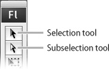
To use these tools, click the item you wish to select. The fundamental difference between them is that the Selection tool is used to select an entire path, while the Subselection tool is used for individual anchor points within a path. A selected anchor point is represented by a filled-in circle; an unselected anchor point is represented by a hollow circle (Figure 7c).
Figure 7c. When you use the Subselection tool to select one or more anchor points in a path, all the anchor points in the path—whether selected or not—become visible.
One of the innovations in Flash was allowing a user to work with vector paths without always having to pay attention to anchor points. For example, if you wanted to change a straight line into a curve in a traditional vector drawing program, you’d have to select the anchor points at each end of the curve and manipulate them. (You can still do this in Flash if you want to; you’ll see how when we look at the Pen tool in #14.) In Flash, however, you can turn a line into a curve simply by dragging a portion of the line outward with the Selection tool.
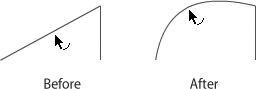
To do this, position the pointer anywhere between two anchor points. A small curve appears next to the pointer, alerting you that dragging from this point will reshape the line or curve (Figure 7d).
Figure 7d. When you see a small curve next to the black arrow, it means that you’re in position to reshape a line or curve.
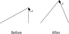
If you position the Selection tool over an anchor point, a small right angle appears next to the pointer (Figure 7e). This alerts you that dragging from this location will change the position of the anchor point itself, rather than reshaping the line or curve that connects two anchor points.
Figure 7e. When you see a small right angle next to the black arrow, it means that you’re in position to move an individual anchor point.
To use either of these techniques, make sure the path that you want to edit isn’t currently selected. (To deselect a selected path, click somewhere outside it with the Selection tool.)
Working with Strokes and Fills
Strictly speaking, a path is a mathematical abstraction: Anchor points have no size, and the lines or curves that connect them have no thickness. To make a path visible, we have to give it a stroke, a fill, or both.
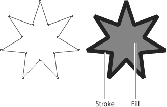
A stroke is an outline; a fill is what occupies the space enclosed by the stroke. A stroke has both weight (thickness) and color; a fill has only color (Figure 8a).
Figure 8a. A plain path is on the left; on the right, the same path has a stroke and fill added.
Drawing tools handle strokes and fills in different ways; for example, the Pencil and Line tools create only strokes, and the Brush tool creates only fills. Most drawing tools are designed to create a stroke and a fill simultaneously, however.
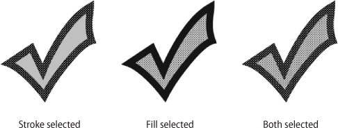
Even when a stroke and a fill are created at the same time with the same tool, Flash considers the stroke and the fill to be separate objects that can be selected and edited individually. To indicate that a stroke or fill has been selected, Flash covers it with a dot screen (Figure 8b).
Figure 8b. The selection dot screen appears black when it’s superimposed over a light-colored stroke or fill, but appears white when it’s superimposed on a dark-colored stroke or fill.
The Selection tool is used with various Flash-specific mouse-click combinations that let you select some or all of a stroke and/or fill:
• To select the portion of a stroke between the two nearest anchor points, single-click the portion of the stroke you want to select.
• To select an entire stroke, double-click anywhere on the stroke.
• To select a fill, single-click the fill.
• To select a path’s entire stroke and fill, double-click the fill.
• If a path has a stroke and you want to add a fill, click the Paint Bucket tool on the toolbar, then click anywhere in the area enclosed by the stroke.
• If a path has a fill and you want to add a stroke, click the Ink Bottle tool on the toolbar, then click the fill.
Another interface feature that’s unique to Flash is the way strokes and fills interact with each other. When you select a path, move it so it overlaps another path, and then deselect it, the following things happen:
• If two stroked paths overlap each other, a new anchor point forms at each place where the strokes intersect.
• If two filled paths overlap each other, the fills are the same color, and the top path has no stroke, the two paths merge into a single path.
• If two filled paths overlap each other and the top fill has a stroke, the top path deletes the portion of the bottom path that’s directly beneath it. This occurs regardless of the fill colors.
• If two filled paths overlap each other and the fills are different colors, the top path deletes the portion of the bottom path that’s directly beneath it. This occurs regardless of whether the top fill has a stroke.
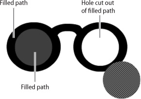
Once you get used to them, these interactions can be useful. For example, the ability of one fill to erase a differently colored fill beneath it makes it easy to cut a hole in a filled path, something that’s more difficult in a traditional vector drawing program such as Illustrator (Figure 8c).
Figure 8c. On the left, two fills of different colors overlap each other. On the right, the top fill is moved away, revealing the eaten-away area underneath.
There may be times, however, when you don’t want strokes or fills to interact in these ways. You can prevent these interactions by doing one of the following:
• Group each stroked or filled path individually before placing it on top of the other. (Grouping, a way of making several objects selectable as a single item, is covered in #17.) Although a group is designed to contain multiple objects, it’s perfectly okay for it to contain just one.
• Place each stroked or filled path on a separate layer. (Layers are covered in #21.)
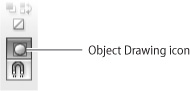
• Before creating each path, click the Object Drawing icon in the options area of the toolbar (Figure 8d). Doing so causes the drawing tool to create a special type of path called a Drawing Object. Like the paths found in traditional vector programs, a Drawing Object has a stroke and fill that are inseparable.
Figure 8d. When a drawing tool is selected, this icon appears in the options area at the bottom of the toolbar. Selecting it causes the drawing tool to create a Drawing Object rather than a standard path.
Choosing Colors
A stroke or fill must have a color. To choose the color for a stroke, click the Stroke Color control on the toolbar. To choose the color for a fill, click the Fill Color control (Figure 9a).
Figure 9a. The Stroke Color and Fill Color controls are in the bottom third of the toolbar. (An identical set of controls is in the upper-left corner of the Color panel.)

When you click the small rectangle on either color control, a pop-up window appears (Figure 9b). Within it, you can choose a color either by clicking a color swatch, or by replacing the contents of the Hex Edit box with a hexadecimal color number, or by clicking the System Color Picker icon, to bring up a color-selection window.
Figure 9b. The pop-up window for selecting colors. (The “No color” icon doesn’t create a colorless stroke or fill; rather it causes Flash to omit the stroke or fill entirely.)

Once you’ve selected a stroke or fill color, it will be applied to all subsequent paths you create until you choose another color. If any paths are selected when you choose a stroke or fill color, the new color is applied to them as well.
Another way to choose stroke and fill colors is to use the Color panel (Figure 9c). (If it’s not part of your workspace, choose Window > Color.) The upper-left corner of the Color panel has color controls identical to those on the toolbar, but the panel also offers two color-selection tools not found elsewhere.
Figure 9c. The Color panel allows you to specify colors by either of two systems: RGB and HSB. You can use the RGB controls either by typing a value into one of the fields, or by clicking the black triangle next to the field to access a slider.

The first tool is a set of RGB sliders for mixing varying amounts of red, green, and blue to get the color you want. (Red, green, and blue can be combined to form any color your computer is capable of displaying.)
The second tool is a set of hue, saturation, and brightness (HSB) controls. Choose a hue and saturation by clicking anywhere in the multicolored square. (Moving horizontally across the square changes the hue; moving up and down increases and decreases the saturation.) Choose a brightness for the selected color by clicking anywhere in the vertical rectangle to the right of the square.
A final way to choose colors is to use the Eyedropper tool. When you select the Eyedropper in the toolbar and click a stroke, the Stroke Color controls in the toolbar and Color Palette display the color of the stroke you clicked. When you click a fill, the Fill Color controls change similarly.
Creating Gradients
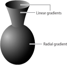
A gradient is a series of colors that blend smoothly into one another. They’re often used to give flat objects the illusion of depth (Figure 10a).
Figure 10a. This simple vase has two kinds of gradient fills.
To create a gradient, you need a starting color and a destination color. If you wish, you can add one or more intermediate colors.
Flash supports two kinds of gradient: linear and radial. A linear gradient proceeds in a straight line from the starting color to the destination color; a radial gradient proceeds outward in a circular pattern, with the starting color at the center of the circle and the destination color at the edge.
The simplest way to create a gradient stroke or fill is to choose one of the gradient swatches from a pop-up window in the Stroke Color or Fill Color control. (See Figure 9b in #9.)
In most cases, the simple black-and-white or primary-colored gradient that you choose from the window won’t suit your needs. You’ll want to modify the colors, or perhaps add some intermediates. You use the Color panel (Figure 10b) to do either.
Figure 10b. When Linear or Radial is selected on the Type menu, the Color panel displays these controls.
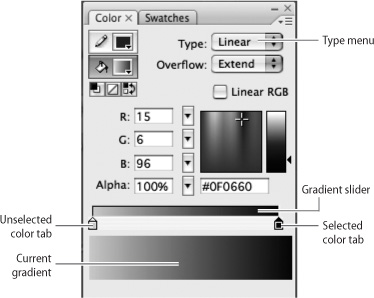
If a gradient fill or stroke is currently selected, or the Fill Color or Stroke Color control is set to a gradient, the Color panel displays that gradient. Otherwise, you can create a new gradient in the Color panel by choosing Linear or Radial from the Type menu.
Initially, the gradient slider has two color tabs, one at each end, representing the starting and destination colors. By default, the starting color is black and the destination color is white. To change either of those colors, click the square part of the appropriate color tab and use any of the controls on the Color panel to choose a color. Alternatively, you can double-click the color tab and choose a swatch from the pop-up menu.
To add a new color to a gradient, click the point in the gradient slider at which you want the new color to appear; an additional color tab will appear at that position. To delete a color from a gradient, drag its color tab away from the gradient slider. To change the position of any color, drag its color tab to the appropriate point along the gradient slider.
In many cases, you’ll not only want to customize your gradient; you’ll also want to change how the gradient is applied to a selected path. If so, choose the Gradient Transform tool from the toolbar and click the stroke or fill that you want to change. (If the Gradient Transform tool isn’t visible in the toolbar, hold down your mouse button over the Free Transform tool and choose Gradient Transform tool from the menu that appears.)
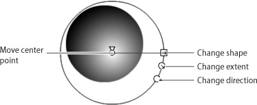
When you click a stroke or path with the Gradient Transform tool, a set of controls appears around the gradient. For linear gradients, the controls allow you to change the extent and direction of the gradient; for radial gradients, the controls also allow you to change the shape and the center point of the gradient (Figure 10c).
Figure 10c. When a radial gradient is selected with the Gradient Transform tool, these controls become available. You can drag the controls to change different characteristics of the gradient.
Setting Options for Drawing Tools
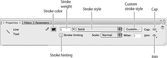
Option controls appear in the options area of the toolbar (the lower portion) and in the Property inspector (Figure 11a). If a tool is selected in the toolbar, these controls affect how the tool operates; if an existing path is selected, these controls change the characteristics of that path.
Figure 11a. This set of option controls appears in the Property inspector when the Line tool is selected in the toolbar. Using other drawing tools, or selecting existing fills or strokes, will cause the options to change.
Aside from the Stroke Color and Fill Color controls, these are the option controls you’re most likely to use regularly:
• Stroke weight. To adjust the lightness or heaviness of a stroke, use the Stroke Weight controls in the Property inspector. You can type a number directly into the field, or you can choose a weight interactively using the slider. (To access the slider, click the black triangle just to the right of the Stroke Weight field.) Note that Flash isn’t consistent in its terminology; stroke weight is also called height or thickness.
• Stroke style. A stroke can appear solid, dotted, or dashed; it can have a hand-drawn or painted look; it can be straight or wavy. To make basic adjustments to the style of a stroke, use the “Stroke style” menu in the Property inspector. To make more elaborate changes, click the Custom button to the right of the slider. A dialog box appears in which you can adjust the type, pattern, wave height, and wave length of a stroke. You can adjust the stroke weight—here called thickness—in the same dialog box.
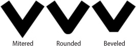
• Stroke caps and joins. The Cap and Join menus are to the right of the Custom button icon in the Property inspector. The Cap menu lets you decide whether the ends of a stroke will be rounded, squared off, or unmodified. The Join menu applies to the points where two segments of a stroke meet: You can decide whether the corners will be mitered, rounded, or beveled (Figure 11b).
Figure 11b. These three paths show the difference between a mitered corner, a rounded corner, and a beveled corner.
• Stroke hinting. Although the objects that you create with the drawing tools are vector objects, they are displayed as bitmaps. In some cases, a stroke may fall into gaps between pixels, making it appear faint or blurry on the screen. Selecting the “Stroke hinting” check box in the Property inspector prevents this from happening.
• Smoothing. This set of controls (a text field and a slider) appears for the tools that require freehand drawing, the Pencil and the Brush. Drawing smooth lines and curves is difficult with a graphics tablet, but it’s almost impossible with a mouse or trackball. Smoothing automatically makes a rough hand-drawn path more regular and gentle. The degree of smoothing can be set anywhere from 0 (no smoothing) to 100. Note that with the Brush tool, a high setting may distort the shape of the brushstroke, making it appear uneven.
• Snap to objects. This option is represented by a horseshoe magnet icon in the options area of the toolbar. If the icon is selected, it makes a path “magnetic,” meaning that the path will try to line up with other objects when you drag and drop it. Other kinds of snapping (to a grid, for example) can be selected from the menu at View > Snapping.
Using the Primitive Shape Tools
Flash offers a variety of shape tools such as ellipses and polygons. In most other programs, these simple shapes are called primitives, but Adobe reserves the term primitive objects for a feature new in Flash CS3: shapes with characteristics that can be changed dynamically by controls in the Property inspector.
Both the standard and primitive shape tools are listed in a single menu in the toolbar, which you can see by holding down your mouse button over the Rectangle tool. The standard shape tools available are the Rectangle, Oval, and Polystar, which can be used to create either polygons or stars. The primitive shape tools are Rectangle Primitive and Oval Primitive; there is as yet no Polystar Primitive tool.
To see the difference between these two types of tools, let’s look at the procedure for drawing a rectangle with rounded corners:
1. Select either the Rectangle or the Rectangle Primitive tool in the toolbar. A set of option controls appears in the Property inspector (Figure 12a).
Figure 12a. These controls appear in the Property inspector for both the Rectangle tool and the Rectangle Primitive tool.

2. Set a corner radius value, either by typing it into the appropriate field in the Property inspector or by using the adjacent slider. The higher the number, the more round the rectangle’s corners will be. The default is for all the corners to be equally round, in which case you enter one value. If you want the corners to have different degrees of roundness, click the Lock icon and then enter a value in each of the four fields.
3. Click and drag the mouse to draw the rectangle on the Stage. The corners are automatically rounded to the degree you specified.
These steps are the same, regardless of whether you use the Rectangle or the Rectangle Primitive tool; but the resulting rectangles have several significant differences:
• Editability. Let’s say you don’t like the setting you used for the corners—you want them to be more rounded. If you drew the rectangle with the Rectangle tool, you can’t change the roundness of the corners; you have to delete the rectangle and draw it again with a new corner radius value. If you drew the rectangle with the Rectangle Primitive tool, you can simply enter a new value in the Property inspector and see the corners change instantly.
• Flexibility. Let’s say you want to reshape the rectangle in some way, such as turning the straight sides into curves or cutting a hole in the middle of the fill. If you drew the rectangle with the Rectangle tool, you can do these kinds of things easily. If you drew the rectangle with the Rectangle Primitive tool, you can’t. The only characteristics of a primitive object that can be changed are those that are controlled from the Property inspector, such as the object’s width, height, and location on the Stage.
• Convertibility. You can convert a primitive object to a drawing object by double-clicking it with the Selection tool and then choosing OK. The reverse is not true: You can’t convert any type of object into a primitive object.
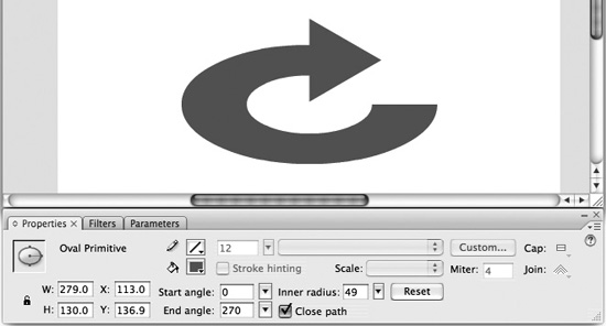
The Oval Primitive tool works like the Rectangle Primitive tool, except that it allows different characteristics to be set: The “Start angle” and “End angle” values allow you to create pie-shaped wedges (or pies with wedges cut out of them); and the “Inner radius” setting allows you to create donut-shaped objects (Figure 12b).
Figure 12b. The curved shaft of this arrow is an oval primitive object, with settings as shown on the Property inspector. The arrowhead is a three-sided polygon made with the Polystar tool.
To create a perfect square, hold down the Shift key while drawing a rectangle with the Rectangle tool or the Rectangle Primitive tool. Similarly, to create a perfect circle, hold down the Shift key while drawing an ellipse with the Oval tool or the Oval Primitive tool.
The shape tools, whether standard or primitive, can be handy for making things other than geometric shapes. In many cases, you’ll find that the easiest way to draw something is to start with a simple shape and modify it. For example, the vase in Figure 10a (see #10) is constructed from two ellipses and a modified rectangle.
Using the Pencil Tool
If you’re accustomed to drawing with pen or pencil on paper, you’ll find the Pencil tool to be intuitive. Simply select it in the toolbar and draw with your mouse (or other input device). Depressing the mouse button creates a new path; releasing the mouse button ends the path.
The line you’ve created is a standard vector path with a stroke applied. You can modify it in the same ways you’d modify any other path—for example, by changing the stroke’s weight or color, or by dragging anchor points with the Subselection tool.
When you select the Pencil tool in the toolbar, a Pencil Mode menu appears in the options area (Figure 13a). The menu gives you three choices:
Figure 13a. This menu appears in the options area of the toolbar when the Pencil tool is selected.

• Straighten. Select this option to convert a curved line into a series of straight line segments. It also activates a shape-recognition feature that allows you to draw smooth geometric shapes. For example, if you use the Pencil tool to draw a path that’s approximately oval-shaped, Flash will convert the path automatically to a perfect oval.
• Smooth. This setting leaves your path fundamentally as you drew it, but makes it smoother and more elegant. This is the option most people prefer: Instead of displaying the path you actually drew, it gives you the path you wanted to draw. The Smoothness control in the Property inspector (see #11) is available only when this option is selected.
• Ink. If you want the path to appear exactly the way you drew it, use this option. Since most input devices (with the possible exception of a stylus and pressure-sensitive tablet) are ill-suited for drawing, you’re not likely to use this setting very often (Figure 13b).
Figure 13b. The same path has been drawn with three different options.

The Pencil tool creates strokes without fills. (The Fill Color control has no effect when the Pencil tool is selected.) If you create a closed path with the Pencil tool and then want to fill it, you can select the Paint Bucket tool and click in the enclosed area of the path.
The Brush tool is similar to the Pencil tool, except that the “brushstrokes” it creates are fills rather than strokes. To add a stroke to a path created by the Brush tool, select the Ink Bottle tool and click the path.
Using the Pen Tool
The Pen may be the most unintuitive tool you’ll ever encounter. If you’re willing to master it, however, you’ll come to appreciate the degree of control that it provides. No other drawing tool can create lines and curves as precisely.
The Pen tool has been upgraded and standardized in Flash CS3. It now works like the Pen tools in Illustrator and Photoshop.
To draw with the Pen tool, there’s one basic rule you must remember: You can’t draw with the Pen tool. More specifically, you can’t use it in the way you’d expect, by dragging your mouse around the Stage.
The Pen tool simply lets you create anchor points. As you create each new anchor point, Flash automatically connects it to the previous one with a line or curve. You can create three kinds of anchor points with this tool (Figure 14a):
Figure 14a. This path contains anchor points of all three types.
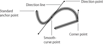
• Anchor point. To create an anchor point with the Pen tool, place the mouse pointer where you want the anchor point to be, and click—that is, press and release the mouse button. If you then create another anchor point (by moving the pointer and clicking again), Flash connects it to the previous one with a straight line. By making several anchor points sequentially, you can create a path consisting of a series of line segments. (We’ll refer to this type as a standard anchor point when necessary to distinguish it from the other two types.)
To end a path, click the Pen tool icon in the toolbar after creating the last anchor point. When you make a new anchor point, Flash won’t connect it to the previous one.
• Smooth-curve point. To create this kind of anchor point, press the mouse button, but don’t release it—instead, drag it outward. As you do so, you’ll see a pair of thin lines, called direction lines, extend outward from the anchor point. These direction lines distinguish a smooth-curve point from a standard anchor point. Each direction line is capped with a diamond-shaped handle called a direction point. When you create a second smooth-curve point, Flash automatically connects it to the previous one with a curve. Read on to learn how to use direction points to control the shape and size of the curve.
• Corner point. A corner point is the place where two curves—or a line and a curve—meet. It’s essentially two anchor points in one; that is, it presents one face to the anchor point before it and another to the anchor point after it. A corner point may be half standard anchor point and half smooth-curve anchor point, or it may be a hybrid of two smooth-curve anchor points. You can recognize a corner point easily because it has only one direction line, or because it has two direction lines that point in different directions.
You can make a corner point by modifying a smooth-curve point. To do so, choose the Subselection tool from the toolbar. Then, while holding down the Alt key (Windows) or Option key (Mac), drag either of the two direction points that are attached to an existing smooth-curve point. In doing so, you convert the smooth-curve point (with two direction lines moving in tandem) to a corner point (with direction lines moving independently of one another). If you want one “face” of the corner point to be a standard anchor point, use the Subselection tool to drag its direction point into the corner point.
To change the size or shape of a curve—regardless of whether it passes through a smooth-curve point or ends at a corner point—simply drag its direction points. (Make sure to do this with the Subselection tool, not the Pen tool.) Each direction point acts like a magnet: When you move it away from the curve, the curve bends to follow it; when you move it toward the curve, the curve moves away from it (Figure 14b).
Figure 14b. You can change the size or shape of a curve by dragging its direction points.

If you hold down the mouse button over the Pen tool icon in the toolbar, you’ll see a menu showing several related tools:
• Add Anchor Point. This tool allows you to add a new anchor point between any pair of existing anchor points.
• Delete Anchor Point. This tool allows you to delete any anchor point from a path.
• Convert Anchor Point. This tool allows you to convert a smooth-curve point into a standard anchor point by clicking it. You can also convert a standard anchor point into a smooth-curve point by dragging outward from the point.
Using the Selection Tools
You already know that the Selection tool (the black arrow) is used to select an entire path, and the Subselection tool (the white arrow) is used to select individual anchor points within a path. Here are other ways in which you might use selection tools:
• Selecting more than one path. Drag the Selection tool to outline a rectangular area on the Stage. When you release the mouse button, any paths within that area are selected. If a path is partly inside and partly outside the rectangular area, only the inside portion is selected.
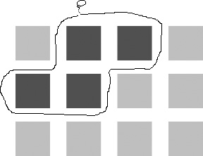
• Selecting more than one path on a crowded Stage. You can use the Lasso tool to outline an irregularly shaped area surrounding the paths you want to select. When you release the mouse button, any paths within that irregular area are selected (Figure 15a). If a path is partly inside and partly outside the area, only the inside portion is selected.
Figure 15a. Outlining an area with the Lasso tool selects any paths (or portions of paths) within that area. The Lasso tool can’t select individual anchor points.
• Selecting more than one anchor point. Drag the Subselection tool to outline a rectangular area on the Stage. When you release the mouse button, any anchor points that are within that rectangular area are selected, regardless of whether they belong to one path or several.
To select only one anchor point, draw a rectangle around it with the Subselection tool, which is often easier than trying to click the point itself.
• Adding to an existing selection. If one or more paths or anchor points are already selected, hold down the Shift key while clicking additional paths with the Selection tool, or anchor points with the Subselection tool. Those paths or anchor points are added to the selection.
• Subtracting from an existing selection. If multiple paths are already selected, hold down the Shift key while you use the Selection tool to click each path that you want to subtract.
• Selecting everything. Use the Selection tool to draw a rectangle around the entire Stage, or choose Edit > Select All.
• Deselecting everything. Use any of the selection tools to click an empty area of the Stage, or choose Edit > Deselect All.
Using the Free Transform Tool
Transforming an object means changing its position, orientation, or proportions. Paths, groups (see #17), and symbol instances (see #23) can be transformed by means of the Free Transform tool.
You can use any of the methods described in #15 to select the objects that you want to transform. Alternatively, you can select objects directly with the Free Transform tool, either by clicking them or stretching a rectangle around them.
When you click the Free Transform tool in the toolbar, any currently selected objects become framed by a black rectangle. The rectangle has eight black squares (handles) around its perimeter—four at the corners, and four midway between each of them—that you can use to perform the transformations (Figure 16a).
Figure 16a. The object inside this black rectangle is ready to be transformed. The pointer looks like a curved arrow, which means that dragging the mouse will rotate the object.

You can transform the selected object or objects in several ways:
• Scaling. Position your pointer directly on any of the eight handles. The pointer becomes a vertical, horizontal, or diagonal double-headed arrow. Depending on the orientation of the arrow, you can drag a handle vertically, horizontally, or both. (The top and bottom center handles adjust height, while the left and right center handles adjust width; the corner handles adjust both dimensions at once.) To scale the object without changing its ratio of width to height, hold down the Shift key while dragging a corner handle.
• Rotation. The white circle in the center of the rectangle is called the transformation point; it’s the point around which the rotation will occur. (Think of it as a pushpin in the middle of a sheet of paper.) If you want to rotate the object around some point other than the center, move the transformation point to the desired spot. Place your pointer a few pixels outward from any of the corner handles. The pointer becomes a curved, double-headed arrow, indicating that you can now rotate the object clockwise or counterclockwise.
• Skewing. Skewing an object means changing the angles at the corners of the selection rectangle, making one pair of angles narrower and one pair wider, while keeping the sides of the rectangle parallel to each other. Place your pointer on the perimeter of the selection rectangle, midway between any two handles. The pointer turns into two overlapping half-arrows, indicating that you can now skew the object by dragging along the axis indicated by the arrows.
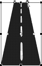
• Distortion. Distorting an object means moving each of its corner handles independently of the others. You can do this by holding down the Control key (Windows) or Command key (Mac) while dragging each corner handle individually. For a perspective distortion effect, do the same thing while holding down the Shift and Control keys (Windows) or Shift and Command keys (Mac) (Figure 16b).
Figure 16b. Tapering an object, otherwise known as distorting it in perspective, causes two sides of the selection rectangle to converge while the other two remain parallel.
Grouping Objects
In #8 you found out how two identically colored fills can merge if they’re allowed to overlap. Combining multiple objects into a single object is often desirable, but the problem with that method of merging paths is that it isn’t reversible. When two or more paths are turned into one, they lose their identities as separate objects.
There are many occasions when you want to treat several objects as a single unit—for convenience in selecting them, for example—but want to retain the option to separate them again. In those situations, grouping is the answer.
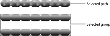
To combine any number of objects into a single group, select them all and choose Modify > Group. This allows them to be selected with a single click (Figure 17a).
Figure 17a. Unlike a path, which displays a dot-screen overlay when it’s selected, a selected group is indicated by a blue rectangle.
A group doesn’t behave like a path. Selecting a group and trying to change its fill color or stroke weight doesn’t work. But if keeping the objects grouped becomes inconvenient, you can easily reverse the process by choosing Modify > Ungroup. All of the formerly grouped objects regain their independent identities, and they can once again be edited or transformed individually.
Often, you’ll want to modify an object within a group, but you won’t want to go through the trouble of ungrouping, making the modifications, and then grouping again. In such cases, you can edit objects within a group without ungrouping them.
To do this, choose the Selection tool and double-click the group on the Stage. Some odd things occur: The paths within the group now sport dot screens to indicate that they’re selected and editable, and everything else on the Stage suddenly becomes dim. What’s happened is that Flash has entered group-editing mode. Think of it as an alternate universe where the group is the only thing that exists.
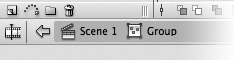
To confirm that Flash is in group-editing mode, look at the narrow divider between the Timeline and the Stage. You’ll see the phrase “Scene 1” on the left, and the word Group just to the right (Figure 17b). These words represent a type of navigation known as a breadcrumb trail. Each time you move from a wider environment to a narrower environment—for example, from the main Stage to the interior of a group or perhaps a symbol inside the group—your progress is charted from left to right on the breadcrumb trail.
Figure 17b. You know that you’re in group-editing mode because the word Group appears at the end of the breadcrumb trail.
While you’re in group-editing mode, you can make whatever changes you want to the objects in the group. Then, to find your way back to where you came from, follow the trail in reverse—that is, from right to left. In this case, if you want to exit group-editing mode, you can click “Scene 1”, which represents the movie as a whole. The word Group disappears from the end of the breadcrumb trail; the group once again acts like a group; and all of the other objects on the Stage become accessible again.
Knowing how to follow the breadcrumb trail will become even more important when we get to #24, “Editing Symbols.”
Simplifying Objects
Keeping the size of the Flash file as small as possible is crucial, because the effectiveness of a SWF file depends partly on how quickly it can be downloaded from the Web.
The fewer the anchor points, the smaller the file is a good rule of thumb in working with vector graphics. If you can get rid of unnecessary anchor points, your animation will look better and play more snappily.
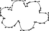
When you work with shape tools and primitive objects, extraneous anchor points are not a problem. But when you use tools such as the Pencil or Brush, you’re likely to have many more anchor points than you need (Figure 18a). Every time your hand-drawn path jiggles or changes direction slightly, Flash creates another anchor point. Even if you use the Pen tool, you’re often tempted to put in extra anchor points because it’s easier than making smooth curves.
Figure 18a. This path, drawn with the Pencil tool, has many more anchor points than it needs.
There are several ways to reduce the number of anchor points in a path:
• Delete the anchor points manually. If you’re comfortable working with smooth-curve points, corner points, and direction lines, you can look for unnecessary anchor points in your path and use the Delete Anchor Point tool to remove them. This is time-consuming, but it gives you full control over the appearance of your paths.
• Smooth your path. You saw in #11 and #13 that the Smoothing controls in the Property inspector can make hand-drawn paths look much cleaner. In most cases, Flash removes unnecessary anchor points as part of the smoothing process. A smoothed path not only looks better; it also yields a smaller file size.
If you didn’t use the Smoothing option when you created your path, you still can. Select the path with the Selection tool, then click the Smooth icon in the options area of the toolbar (Figure 18b). You can click this icon repeatedly; each time you do, the path gets a little smoother. Another way to do the same thing is to select Modify > Shape > Smooth; you can do that repeatedly as well.
Figure 18b. Each time you click this icon, your selected path gets smoother.

• Optimize your path. The automated way to simplify a path is to select the path and then choose Modify > Shape > Optimize. The resulting dialog box allows you to choose a degree of smoothing from None to Maximum. When you do so and click OK, Flash does the optimization and shows you the result, including a count of how many curves—essentially anchor points—were eliminated.
You’ll almost always want to select “Use multiple passes (slower)” in the Optimize Curves dialog box. This option does slow down the process, but not drastically so, and it usually yields better results.
Unlike the Simplify command in Illustrator, the Optimize command in Flash offers no preview. The only way to find the best setting for a particular path is by trial and error. A good strategy is to start with the maximum and see what that does to your path. If the path is too distorted, you can undo the optimization and try it again with a slightly lower degree of optimization.
Working with Text
Most of your Flash movies will contain text of one kind or another. If you’ve ever used a word processor, you should be comfortable with the way Flash handles text.
To add text to the Stage, select the Text tool from the toolbar. The Property inspector fills up with options, the most important of which is the “Text type” menu on the left side. Make sure the menu says Static Text. (The other options—Dynamic Text and Input Text—are for specialized ActionScript applications.)
Use the Text tool to drag a rectangle across the Stage. Make the rectangle as wide as you want your text block to be, but remember that you can adjust the width at any time by dragging the white square at the upper-right corner of the rectangle (Figure 19a). A blinking cursor appears inside the rectangle, indicating that Flash is ready to accept your text entry.
Figure 19a. As you type, the text wraps to a new line when it reaches the right side of the rectangle.

Options such as font, size, color, alignment, and so forth should be self-explanatory. It’s worth pointing out, however, that Flash allows the text size to be set dynamically by means of a slider. You can select a block of text and move the slider up and down until the size looks right.
When you include text in a movie, it’s important to understand how Flash handles fonts. You can use a particular font only if that font is installed on the computer you’re using. When you test or publish your movie, a subset of the font is embedded in the SWF file, so anyone who watches the movie will see the text in the correct font and size. However, no font information is embedded in a FLA file. If you give your FLA file to colleagues or clients, be sure their computers have the necessary fonts installed. Otherwise, they’ll be prompted to choose replacement fonts when they open the FLA file.
Anti-aliasing is the process used by Flash and other programs to make text and images look smoother onscreen. The Property inspector in Flash CS3 includes a Font Rendering Method menu that lets you set anti-aliasing options for each text field you create. If the text you’re creating will be put into motion, you’ll generally want to choose “Anti-alias for animation.” If the text will be static, you’ll get better results with “Anti-alias for readability.” If you use extremely small text, it will probably be most readable with no smoothing at all. In that case, you’d choose “Bitmap text (no anti-alias).”
Breaking Apart Text
A block of text in Flash is known as a text object, which is a self-contained unit. If you move, resize, or delete a text object, all of its text is affected.
Sometimes you may not want your text to behave as a single object, though. For example, you may want to animate an explosion, scattering all the text onscreen randomly. To do this, you have to convert your text from a single object to many; in fact, every character needs to be a separate object.
The Break Apart command on the Modify menu is ideal for situations like this. Break Apart does different things in different situations. When applied to a text object that contains two or more characters, Break Apart turns each into a separately selectable object (Figure 20a).
Figure 20a. From left to right: a selected text object, the same text with Break Apart applied once; the same text with Break Apart applied twice.

You can apply the Break Apart command a second time to the same text. Applying it once breaks the text object into individual characters; applying it a second time converts each character into an editable vector path. Using Break Apart in this way has advantages and drawbacks:
• Advantages. When text characters have been converted to vector shapes, the computer no longer needs a specific font installed to display the text. You can save your FLA file and pass it on knowing that the text will display correctly. Also, converted text characters can be edited like any other vector path, allowing you to experiment with interesting typographical effects (Figure 20b).
Figure 20b. After being broken apart twice, text characters can be edited like ordinary vector paths.

• Drawbacks. Breaking text apart is irreversible: Individual characters can’t be turned back into an editable text block. If you need to change the content, spelling, typeface, anti-aliasing, or any other characteristic of the text, you’ll have to input it all over again. Also, converting each individual character to a vector path may add an excessive number of anchor points, bloating the file size.
Using Multiple Layers
Every new FLA file begins with a single layer. You can see it in the left column of the Timeline, labeled Layer 1.
Practically speaking, you need only one layer to create a vector drawing. That’s because every time you create a new object, Flash stacks it on top of the previous ones in the same layer. The position of an object in relation to the others in the stack is known as its depth level.
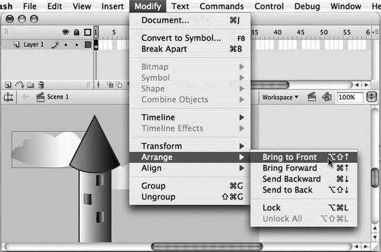
To change the depth level of a particular object, use the commands under Modify > Arrange. For example, let’s say a cloud is behind a building, and you want it to be in front. You could accomplish this by selecting the cloud and choosing Modify > Arrange > Bring to Front (Figure 21a).
Figure 21a. The Bring to Front command lets you bring an object up to the highest depth level.
The other commands on the Arrange submenu are Bring Forward, which moves a selected item up one depth level at a time; Send Backward, which moves the item down one depth level at a time; and Send to Back, which moves the item to the lowest possible depth level.
Using the Modify > Arrange commands can be tedious, especially if you have objects with different depth levels on one layer, so you may choose to distribute your objects among different layers.
Unlike Photoshop and Illustrator, each of which has a dedicated Layers palette, Flash displays all of its layers in the Timeline. To create a new layer in the Timeline, click the Insert Layer icon (Figure 21b). Each new layer is numbered by default, but you can change a layer’s name by double-clicking the current name and typing a new one.
Figure 21b. Layer names are displayed in the leftmost column of the Timeline.

Once you have multiple layers in the Timeline, you have to keep track of which layer is active at any given time. The active layer is highlighted in blue. Any object that you create is automatically placed on the active layer. If you want a new object to be on a different layer, first select your preferred layer in the Timeline to make it active.
If an object is on one layer and you want to move it to another, select the object and choose Edit > Cut. Then select the layer to which you want the object moved and choose Edit > Paste in Place (if you want the object to have the same position on the Stage as it did before) or Edit > Paste in Center (if you want the object to appear in the middle of the Stage).
Layers that are higher up in the Timeline appear in front of layers that are lower down. You can drag any layer up or down.
There are three columns in the Timeline to the right of the layer names, and they affect the way the objects in each layer are displayed. Each has an “on” and an “off” setting; you can toggle between settings by clicking in the appropriate column and row.
The first column, with the Eye icon at the top, controls the visibility of each layer. A dot in column means the corresponding layer is visible; a red X means the layer is hidden.
The second column, with the Padlock icon at the top, controls the security of each layer. A dot in that column means the corresponding layer is unlocked; a padlock symbol means the layer is locked. No objects can be copied from, pasted to, or edited on a locked layer.
The third column, with the empty square at the top, controls the display mode of each layer. A filled square in that column means the layer is set to display strokes and fills; an empty square means the layer is set to display only unadorned paths. If you have a slow computer, turning off the display of strokes and fills may make the screen refresh faster and speed up your work.
Clicking the icon at the top of each column turns the corresponding setting on or off for all the layers.