
PROJECT 2: LIGHT DIMMER
IN THIS PROJECT, YOU’LL CREATE A DIMMER SWITCH BY ADDING A POTENTIOMETER TO CONTROL THE BRIGHTNESS OF AN LED.

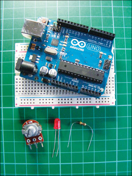
PARTS REQUIRED
• Arduino board
• Breadboard
• Jumper wires
• LED
• 50k-ohm potentiometer
• 470-ohm resistor
A potentiometer is a variable resistor with a knob that allows you to alter the resistance of the potentiometer as you turn it. It is commonly used in electrical devices such as volume controls on audio equipment. This project uses a 50k-ohm potentiometer.
HOW IT WORKS
The potentiometer manipulates a continuous analog signal, which represents physical measurements. Humans perceive the world in analog; everything we see and hear is a continuous transmission of information to our senses. This continuous stream is what defines analog data. Digital information, on the other hand, estimates analog data using only numbers. To approximate the continuous analog data from the potentiometer, the Arduino must represent the signal as a series of discrete numbers—in this case, voltages. The center pin of the potentiometer sends the signal to an Arduino analog IN—any pin from A0 to A5—to read the value.
The LED is actually being switched on and off, but it happens so quickly that our eyes compensate and we see a continuously lit LED at varying light levels. This is known as persistence of vision.
To create persistence of vision, the Arduino uses a technique called pulse width modulation (PWM). The Arduino creates a pulse by switching the power on and off very quickly. The duration that the power is on or off (known as the pulse width) in the cycle determines the average output, and by varying this pulse width the pattern can simulate voltages between full on (5 volts) and off (0 volts). If the signal from the Arduino is on for half the time and off for half, the average output will be 2.5 volts, halfway between 0 and 5. If the signal is on for 80 percent and off for 20 percent, then the average voltage is 4 volts, and so on. You can vary the signal, which in turn varies the pulse width, by turning the potentiometer left or right, increasing or decreasing the resistance.
Using this technique, you can change the voltage sent to the LED and make it dimmer or brighter to match the analog signal from the potentiometer. Only pins 3, 5, 6, 9, 10, or 11 on the Arduino can use PWM. Figure 2-1 gives examples of how PWM would look as a waveform.
FIGURE 2-1:
Pulse width modulation as a waveform

THE BUILD
Insert the potentiometer into your breadboard and connect the center pin to the Arduino’s A0 pin. Connect one of the outer pins to the +5V rail of the breadboard and the other outer pin to GND on the breadboard (it doesn’t actually matter which way around the outer potentiometer pins are connected; these instructions just reflect the diagrams in this project), as shown in Figure 2-2.
FIGURE 2-2:
Connecting the potentiometer to the Arduino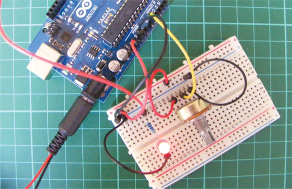
POTENTIOMETER
ARDUINO
Left pin
+5V
Center pin
A0
Right pin
GND
Insert the LED into the breadboard. Attach the positive leg (the longer leg) to pin 9 of the Arduino via the 470-ohm resistor, and the negative leg to GND, as shown in Figure 2-3.
LED
ARDUINO
Positive leg
Pin 9
Negative leg
GND via 470-ohm resistor
FIGURE 2-3:
Circuit diagram for the light dimmer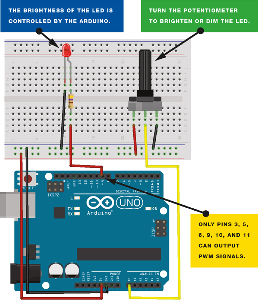
Upload the code in “The Sketch” below.
Turn the potentiometer to control the brightness of the LED.
This project has many potential uses: you can cluster a number of LEDs together to create an adjustable flashlight, a night-light, a display case light, or anything else that uses dimming lights.
THE SKETCH
This sketch works by setting pin A0 as your potentiometer and pin 9 as an OUTPUT to power the LED. You then run a loop that continually reads the value from the potentiometer and sends that value as voltage to the LED. The voltage value is between 0–5 volts, and the brightness of the LED will vary accordingly.
/* http://arduino.cc/en/Reference/AnalogWrite by Tom Igoe
from http:itp.nyu.edu/physcomp/Labs/AnalogIn */
int potPin = A0; // Analog input pin connected to the potentiometer
int potValue = 0; // Value that will be read from the potentiometer
int led = 9; // Pin 9 (connected to the LED) is capable of PWM
// Runs once at beginning of the program
void setup() {
pinMode(led, OUTPUT); // Set pin 9 to output
}
// Loops continuously
void loop() {
potValue = analogRead(potPin); // Read potentiometer value
// from A0 pin
analogWrite(led, potValue/4); // Send potentiometer value to LED
// to control brightness with PWM
delay(10); // Wait for 10 ms
}