
PROJECT 23: WIRELESS ID CARD ENTRY SYSTEM
IN THIS PROJECT, WE’LL USE A RADIO FREQUENCY IDENTIFICATION (RFID) READER TO BUILD A WIRELESS ID CARD ENTRY SYSTEM.


PARTS REQUIRED
• Arduino board
• Breadboard
• Jumper wires
• Mifare RFID-RC522 module
• Tower Pro SG90 9g servomotor
• Piezo buzzer
• Red LED
• Green LED
• 2 220-ohm resistors
LIBRARIES REQUIRED
• RFID
• SPI
• Wire
• Servo
• Pitches
HOW IT WORKS
An RFID reader uses wireless technology to identify a card, tag, or key fob without contact. The reader will respond when the card is placed near it. First, we need the reader to read the unique number of our RFID card, and then we’ll add a servo that will move depending on whether the RFID reader recognizes the card. We could use this ID system for something like a door or box lock, as with the secret knock code lock in Project 9.
You may have seen a sticker like the one in Figure 23-1 on an item you have purchased. These stickers use RFID to allow the store to track items for security purposes. If you pass through the RFID field at the exit without paying, the stickers will set off the alarm. RFID readers and cards are also often used as identification to allow access into restricted areas, like top-secret labs or gated communities.

There are two types of RFID: passive and active. Each RFID system uses a radio frequency to exchange a signal between the reader and the tag or card. This signal contains the tag or card’s unique code, and if the RFID reader recognizes that code, it reacts appropriately—for example, by allowing the item to pass through the detectors in a store or by unlocking a door.
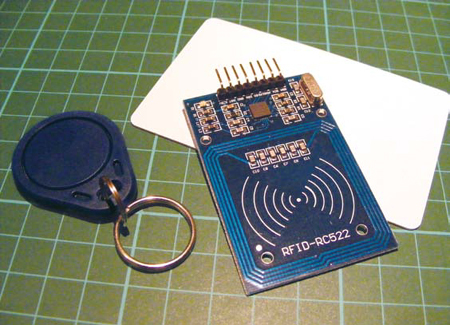
In a passive system, when the two are passed close to each other, the reader’s radio signal powers the circuit in the tag or card just enough for them to exchange data. Active systems have a powered reader and a powered tag and can read tags accurately from much farther away. Active systems are very expensive and used for more sophisticated applications, so we’ll be using a passive RFID system: the Mifare RFID-RC522 reader, which comes with a blank card and key fob, like those shown in Figure 23-2. The reader operates at 13.56 MHz, which means it can identify the card or fob, each of which is powered by the reader, only if it is less than a few inches away. It’s important to keep this in mind when positioning your reader.
FIGURE 23-2:
RFID reader with card and key fob
We’ll create an RFID-controlled servo. When you pass your card in front of the RFID reader, it reads the card. If the module recognizes the card and the card has access rights, the green LED lights up, a tune plays, and the servomotor moves 180 degrees. If the module does not recognize the card, the red LED lights up, a different tune plays, and the servo does not move.
Table 23-1 describes the various functions of the RFID reader.
TABLE 23-1:
Functions of the RFID reader pins
RFID |
DETAIL |
NOTES |
3.3V |
3.3 volts |
The module can use only this amount of voltage. |
RST |
Reset |
Will clear the module to initial state. |
GND |
Ground |
Connects to the Arduino GND pin. |
IRQ |
Interrupt Request |
Not used in this project. |
MISO |
Master In Slave Out |
Sometimes referred to as “data in.” |
MOSI |
Master Out Slave In |
Sometimes referred to as “data out.” |
SCK |
Serial Clock |
Output from master. This creates a pulse that synchronizes data, usually set by the master. |
SDA/SS |
Serial Data/Slave Select |
Modules will have either SDA or SS, although they are the same. This is how the Arduino and module share data and communicate. |
Pin 16 |
VCC |
Positive power. |
THE BUILD
You may need to set up the module by soldering the header pins to it first. Snap off a strip of eight header pins. Solder one header pin to each point. Make sure to hold the solder iron in place for only a few seconds so you don’t damage the circuits. See the “Quick Soldering Guide” on page 18 for a primer on soldering.
Place your RFID module into a breadboard as shown in Figure 23-3, and then connect the RFID pins to the Arduino pins as indicated in the following table. Remember to connect the RFID board to 3.3V power on the Arduino (not +5V), or you will damage the module.
FIGURE 23-3:
Placing the RFID module into the breadboard
RFID
ARDUINO
3.3V
3.3V
RST
Pin 5
GND
GND
IRQ
Not used
MISO
Pin 12
MOSI
Pin 11
SCK
Pin 13
SDA
Pin 10
Now we need to check that the RFID module is working. Download the RFID library from http://www.nostarch.com/arduinohandbook/ and save it in your libraries directory (see “Libraries” on page 7 for details on downloading libraries). Upload the following test sketch for the RFID reader. Keep the USB cable from your PC connected to the Arduino.
// RFID Library Created by Miguel Balboa (circuitito.com)
#include <SPI.h>
#include <RFID.h>
#define SS_PIN 10
#define RST_PIN 9
RFID rfid(SS_PIN, RST_PIN);
// Setup variables
int serNum0;
int serNum1;
int serNum2;
int serNum3;
int serNum4;
void setup() {
Serial.begin(9600);
SPI.begin();
rfid.init();
}
void loop() { // This loop looks for a card(s) to read
if (rfid.isCard()) {
if (rfid.readCardSerial()) {
if (rfid.serNum[0] != serNum0
&& rfid.serNum[1] != serNum1
&& rfid.serNum[2] != serNum2
&& rfid.serNum[3] != serNum3
&& rfid.serNum[4] != serNum4
) {
// When a card is found, the following code will run
Serial.println(" ");
Serial.println("Card found");
serNum0 = rfid.serNum[0];
serNum1 = rfid.serNum[1];
serNum2 = rfid.serNum[2];
serNum3 = rfid.serNum[3];
serNum4 = rfid.serNum[4];
// Print the card ID to the Serial Monitor of the IDE
Serial.println("Cardnumber:");
Serial.print("Dec: ");
Serial.print(rfid.serNum[0], DEC);
Serial.print(", ");
Serial.print(rfid.serNum[1], DEC);
Serial.print(", ");
Serial.print(rfid.serNum[2], DEC);
Serial.print(", ");
Serial.print(rfid.serNum[3], DEC);
Serial.print(", ");
Serial.print(rfid.serNum[4], DEC);
Serial.println(" ");
Serial.print("Hex: ");
Serial.print(rfid.serNum[0], HEX);
Serial.print(", ");
Serial.print(rfid.serNum[1], HEX);
Serial.print(", ");
Serial.print(rfid.serNum[2], HEX);
Serial.print(", ");
Serial.print(rfid.serNum[3], HEX);
Serial.print(", ");
Serial.print(rfid.serNum[4], HEX);
Serial.println(" ");
} else {
// If the ID matches, write a dot to the Serial Monitor
Serial.print(".");
}
}
}
rfid.halt();
}Open the Arduino Serial Monitor in your IDE.
Pass either your card or key fob in front of the RFID module. The unique number should appear on the Serial Monitor, as shown in Figure 23-4. Write down this number, because you’ll need it later. In this case, my card number is 4D 55 AD D3 66.
FIGURE 23-4:
The RFID number represented in hexadecimal on the screen
Insert the two LEDs into the breadboard, with the shorter, negative wires connected to the GND rail. Connect the longer, positive wire on the red LED to Arduino pin 3 via a 220-ohm resistor. Connect the positive leg of the green LED to pin 2 via another 220-ohm resistor.
LEDS
ARDUINO
Negative legs
GND
Positive leg (red)
Pin 3 via 220-ohm resistor
Positive leg (green)
Pin 2 via 220-ohm resistor
Connect the servo to the Arduino by attaching the red wire to +5V, the brown (or black) wire to GND, and the yellow wire to Arduino pin 9.
SERVO
ARDUINO
Red wire
+5V
Black wire
GND
Yellow wire
Pin 9
Connect the piezo buzzer to the Arduino by attaching the red wire to Arduino pin 8 and the black wire to GND. Your build should now look something like Figure 23-5.
PIEZO
ARDUINO
Red wire
Pin 8
Black wire
GND
FIGURE 23-5:
Completed RFID project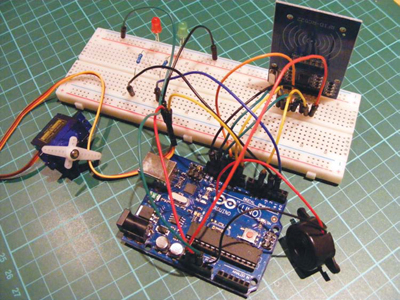
Open the project code in your Arduino IDE and change the following line to match the hex number you found for your card or key fob in step 5 using the RFID reader. Leave the 0x as it appears, but fill in the rest with your number.
byte card[5] = {0x4D,0x55,0xAD,0xD3,0x66};
Confirm that your setup matches the circuit diagram in Figure 23-6, and then upload the code from “The Sketch” on page 203 to your Arduino.
FIGURE 23-6:
Circuit diagram for the wireless ID card entry system
THE SKETCH
The sketch begins by calling on the SPI, RFID, Servo, Pitches, and Wire libraries to control communication between the Arduino, RFID module, and servo. Two melodies are defined, one for a positive reading on your card and the other for a negative reading. The green LED is set to Arduino pin 2, the red LED to pin 3, the piezo buzzer to pin 8, and the servo to pin 9.
The following line is where you add your card’s hex value:
byte card[5] = {0x4D,0x55,0xAD,0xD3,0x66};
Pass your card in front of the reader. If the hex code on the card matches that in your sketch, the green LED lights up, a tune plays, and the servo moves. The reader rejects all other cards unless you add their number to the code at ➊. If a card is rejected, the red LED lights up and a different tune plays, but the servo does not move.
#include <SPI.h>
#include <RFID.h>
#include <Servo.h>
#include "pitches.h"
#include <Wire.h>
RFID rfid(10, 5); // Define the RFID
// Replace this with the code from your card in hex form
➊ byte card[5] = {0x4D,0x55,0xAD,0xD3,0x66};
// List any other codes for cards with access here
byte serNum[5];
byte data[5];
// Define the melodies for successful access and denied access
int access_melody[] = {NOTE_G4, 0, NOTE_A4, 0, NOTE_B4, 0, NOTE_A4,
0, NOTE_B4, 0, NOTE_C5, 0};
int access_noteDurations[] = {8, 8, 8, 8, 8, 4, 8, 8, 8, 8, 8, 4};
int fail_melody[] = {NOTE_G2, 0, NOTE_F2, 0, NOTE_D2, 0};
int fail_noteDurations[] = {8, 8, 8, 8, 8, 4};
int LED_access = 2; // Pin connected to green LED
int LED_intruder = 3; // Pin connected to red LED
int speaker_pin = 8; // Pin connected to piezo buzzer
int servoPin = 9; // Pin connected to servo
Servo doorLock; // Define the servomotor
void setup() {
doorLock.attach(servoPin); // Set servo as a pin
Serial.begin(9600); // Start serial communication
SPI.begin(); // Start serial communication between the RFID and PC
rfid.init(); // Initialize the RFID
Serial.println("Arduino card reader");
delay(1000);
pinMode(LED_access, OUTPUT);
pinMode(LED_intruder, OUTPUT);
pinMode(speaker_pin, OUTPUT);
pinMode(servoPin, OUTPUT);
}
void loop() { // Create a variable for each user
boolean card_card = true; // Define your card
if (rfid.isCard()) {
if (rfid.readCardSerial()) {
delay(1000);
data[0] = rfid.serNum[0];
data[1] = rfid.serNum[1];
data[2] = rfid.serNum[2];
data[3] = rfid.serNum[3];
data[4] = rfid.serNum[4];
}
Serial.print("Card found - code:");
for (int i = 0; i < 5; i++) {
// If it is not your card, the card is considered false
if (data[i] != card[i]) card_card = false;
}
Serial.println();
if (card_card) { // A card with access permission is found
Serial.println("Hello!"); // Print to Serial Monitor
for (int i = 0; i < 12; i++) { // Play welcome music
int access_noteDuration = 1000 / access_noteDurations[i];
tone(speaker_pin, access_melody[i], access_noteDuration);
int access_pauseBetweenNotes = access_noteDuration * 1.30;
delay(access_pauseBetweenNotes);
noTone(speaker_pin);
}
}
else { // If the card is not recognized
// Print message to Serial Monitor
Serial.println("Card not recognized! Contact administrator!");
digitalWrite(LED_intruder, HIGH); // Turn on red LED
for (int i = 0; i < 6; i++) { // Play intruder melody
int fail_noteDuration = 1000 / fail_noteDurations[i];
tone(speaker_pin, fail_melody[i], fail_noteDuration);
int fail_pauseBetweenNotes = fail_noteDuration * 1.30;
delay(fail_pauseBetweenNotes);
noTone(speaker_pin);
}
delay(1000);
digitalWrite(LED_intruder, LOW); // Turn off red LED
}
if (card_card) { // Add other users with access here
Serial.println("Access granted.......Welcome!");
digitalWrite(LED_access, HIGH); // Turn on green LED
doorLock.write(180); // Turn servo 180 degrees
delay(5000); // Wait for 5 seconds
doorLock.write(0); // Turn servo back to 0 degrees
digitalWrite(LED_access, LOW); // Turn off green LED
}
Serial.println();
delay(500);
rfid.halt();
}
}