PROJECT 13: WEATHER STATION
IN THIS PROJECT YOU’LL SET UP A WEATHER STATION TO MEASURE TEMPERATURE AND HUMIDITY, AND DISPLAY THE VALUES ON AN LCD SCREEN.


PARTS REQUIRED
• Arduino board
• Breadboard
• Jumper wires
• 50k-ohm potentiometer
• 16x2 LCD screen (Hitachi HD44780 compatible)
• DHT11 humidity sensor
LIBRARIES REQUIRED
• LiquidCrystal
• DHT
HOW IT WORKS
The humidity sensor used in this project is the relatively cheap DHT11, shown in Figure 13-1, which measures both humidity and temperature. It uses a capacitive humidity sensor and resistive-type temperature sensor to take a reading from its environment. It sends this reading to the Arduino as voltage, and the Arduino converts this to readable values displayed on the screen. For best results, you should mount your sensor on an outside wall with a decent amount of open space. You’ll want to mount your LCD screen indoors or seal it carefully in a clear, waterproof bag or casing to keep it protected from the elements.
FIGURE 13-1:
The DHT11 measures both temperature and humidity.
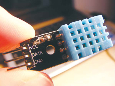
The DHT11 comes with either four pins or three pins. The sensor shown in Figure 13-1 has four pins, but you can use either version for this project, because you won’t be using pin 3. Check the retailers at the beginning of the book for ideas on where to buy a DHT11.
THE BUILD
First, prepare the LCD screen as per the soldering instructions in “Preparing the LCD Screen” on page 104. Insert the DHT11 sensor into your breadboard. The DHT11 pins are numbered 1 to 4 (or 3) from the left, when the front is facing you. Connect pin 1 to the +5V rail, connect pin 2 directly to Arduino pin 8, and connect pin 4 (or 3) to GND.
DHT11
ARDUINO
Pin 1
+5V
Pin 2
Pin 8
Pin 3
Not used
Pin 4
GND
Insert the LCD screen into the breadboard and connect the pins to the Arduino as shown in the following table and in Figure 13-2. The GND and +5V rails will have multiple connections.
LCD SCREEN
ARDUINO
1 VSS
GND
2 VDD
+5V
3 VO contrast
Potentiometer center pin
4 RS
Pin 12
5 R/W
GND
6 Enable
Pin 11
7 D0
Not used
8 D1
Not used
9 D2
Not used
10 D3
Not used
11 D4
Pin 5
12 D5
Pin 4
13 D6
Pin 3
14 D7
Pin 2
15 A BcL +
+5V
16 K BcL –
GND
FIGURE 13-2:
Inserting the LCD screen into the breadboard
Insert a potentiometer into the breadboard as shown in Figure 13-3 and connect the center pin to LCD pin 3. Connect one outer pin to the +5V rail and the other to the GND rail.
FIGURE 13-3:
Inserting the potentiometer into the breadboard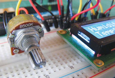
Remember to connect the power rails of the breadboard to Arduino GND and +5V. Confirm that your setup matches the circuit diagram in Figure 13-4, and upload the code in “The Sketch” on page 116.
FIGURE 13-4:
The circuit diagram for the weather station
THE SKETCH
This sketch uses the LiquidCrystal library, which comes with the Arduino IDE, and the DHT library, which you will need to download and install from http://nostarch.com/arduinohandbook/ (see “Libraries” on page 7). The DHT library controls the function of the sensor, and the LCD library displays the readings on the screen.
/* Example testing sketch for various DHT humidity/temperature
sensors. Written by ladyada, public domain. */
#include <LiquidCrystal.h>
#include "DHT.h" // Call the DHT library
#define DHTPIN 8 // Pin connected to DHT
LiquidCrystal lcd(12, 11, 5, 4, 3, 2);
#define DHTTYPE DHT11 // Define the type of DHT module
DHT dht(DHTPIN, DHTTYPE); // Command to the DHT.h library
void setup() {
dht.begin(); // Start the sensor
lcd.begin(16, 2); // LCD screen is 16 characters by 2 lines
}
void loop() {
float h = dht.readHumidity(); // Value for humidity
float t = dht.readTemperature(); // Value for temperature
t = t * 9 / 5 + 32; // Change reading from Celsius to Fahrenheit
if (isnan(t) || isnan(h)) { // Check that DHT sensor is working
lcd.setCursor(0, 0);
lcd.print("Failed to read from DHT"); // If DHT is not working,
// display this
} else { // Otherwise show the readings on the screen
lcd.clear();
lcd.setCursor(0, 0);
lcd.print("Humidity: ");
lcd.print(h);
lcd.print("%");
lcd.setCursor(0, 1);
lcd.print("Temp: ");
lcd.print(t);
lcd.print("f");
}
}