
PROJECT 22: KEYPAD ENTRY SYSTEM
IT’S TIME TO INTRODUCE A KEYPAD TO YOUR ARDUINO BY BUILDING A KEYPAD ENTRY SYSTEM.


PARTS REQUIRED
• Arduino board
• Breadboard
• Jumper wires
• Tower Pro SG90 9g servomotor
• Green LED
• Red LED
• 4×4 membrane keypad
• 2 220-ohm resistors
LIBRARIES REQUIRED
• Keypad
• Servo
• Password
This project uses a 4×4 membrane keypad with a ribbon of eight wires running from the bottom, connected to a servo that sweeps to open a lock.
HOW IT WORKS
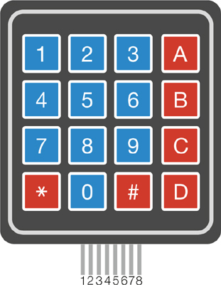
A keypad is basically a series of buttons that output a number or character depending on which button is pressed. With the keypad face up, the wires are numbered 1–8 from left to right. The first four wires correspond to the rows, and the latter four to the columns.
You’ll need to download the library for the keypad from the http://nostarch.com/arduinohandbook/ and save it in your IDE’s Arduino libraries folder.
We’ll connect this keypad to a servo and some LEDs to create a lock system like the secret knock lock in Project 9. To use the lock, enter your code and press the asterisk (*) to confirm. If the code matches the password defined in the sketch, the green LED will flash and the servo will move 90 degrees. If the code is incorrect, the red LED will flash. Use the hash key (#) to reset between code inputs. You could swap this servo for a more substantial one capable of unlocking a heavier deadbolt on a door, or locking and unlocking a box from the inside with the keypad and LEDs mounted externally.
TESTING THE KEYPAD
First we’ll test the keypad with the following code:
#include <Keypad.h>
const byte ROWS = 4;
const byte COLS = 4;
char keys[ROWS][COLS] = {
{'1','2','3','A'},
{'4','5','6','B'},
{'7','8','9','C'},
{'*','0','#','D'}
};
byte rowPins[ROWS] = {2,3,4,5};
byte colPins[COLS] = {6,7,8,9};
Keypad keypad = Keypad(makeKeymap(keys), rowPins, colPins,
ROWS, COLS);
void setup() {
Serial.begin(9600);
}
void loop() {
char key = keypad.getKey();
if (key != NO_KEY){
Serial.println(key);
}
}
Upload this code and then open the Serial Monitor in your IDE (Figure 22-1).
FIGURE 22-1:
Testing the keypad
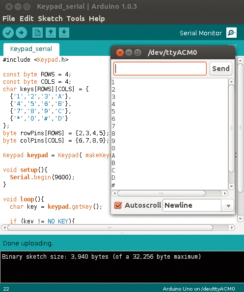
With the keypad face up, connect the wires in sequence from left to right to Arduino digital pins 9–2. Once you have uploaded the code, press a few keys. As each key is pressed, the corresponding character should appear on a separate line in the Arduino IDE’s serial console.
THE BUILD
Connect the pins of the keypad directly to the Arduino pins as follows. The keypad pins are numbered as shown in Figure 22-2.
KEYPAD
ARDUINO
Pin 1
Pin 9
Pin 2
Pin 8
Pin 3
Pin 7
Pin 4
Pin 6
Pin 5
Pin 5
Pin 6
Pin 4
Pin 7
Pin 3
Pin 8
Pin 2
Place a green LED and a red LED into the breadboard with the shorter, negative legs connected to the Arduino GND rail. Add a 220-ohm resistor to each longer, positive leg. Connect the resistor that’s attached to the green LED to Arduino pin 11, and the resistor that’s attached to the red LED to Arduino pin 12.
LEDS
ARDUINO
Positive legs
Pins 11 and 12 via 220-ohm resistors
Negative legs
GND
Now attach the servo (see Figure 22-3). Connect the brown wire to the GND rail, the red wire to the +5V rail, and the yellow/white wire directly to pin 13 on the Arduino.
SERVO
ARDUINO
Brown wire
GND
Red wire
+5V
Yellow wire
Pin 13
FIGURE 22-3:
Attaching the servo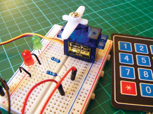
Make sure your setup matches that of Figure 22-4, and upload the code in “The Sketch” on page 192.
FIGURE 22-4:
Circuit diagram for the keypad entry system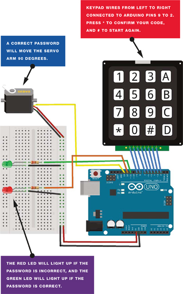
THE SKETCH
First, the sketch calls on the Keypad, Servo, and Password libraries. The Servo library is included in the IDE, but you’ll have to download the Keypad and Password libraries (http://nostarch.com/arduinohandbook/). We then set the eight pins that will determine the input from the keypad, and set Arduino pins 11 and 12 to control the LEDs and pin 13 to control the servomotor. The Arduino waits for your code input from the keypad and for you to confirm your input with *. Once you’ve pressed the asterisk key, the sketch will check the entry against the password in the code. If the entry doesn’t match the password, the red LED will be set to HIGH and light; if the entry does match the password, the green LED will be set to HIGH and light, and the servomotor will turn. Pressing # will reset the sketch so it’s ready for another entry.
To alter the password, change the number in quotation marks in the following line.
Password password = Password("2468");
The default password in the sketch is 2468.
/* Keypad Library for Arduino
Authors: Mark Stanley, Alexander Brevig
http://playground.arduino.cc/Main/KeypadTutorial
*/
#include <Password.h>
#include <Keypad.h>
#include <Servo.h>
Servo myservo;
Password password = Password("2468"); // Set password
const byte ROWS = 4; // Set four rows
const byte COLS = 4; // Set four columns
char keys[ROWS][COLS] = { // Define the keymap
{'1','2','3','A'},
{'4','5','6','B'},
{'7','8','9','C'},
{'*','0','#','D'}
};
byte rowPins[ROWS] = { 9,8,7,6 }; // Pins connected to keypad
// ROW0, ROW1, ROW2 and ROW3
byte colPins[COLS] = { 5,4,3,2, }; // Pins connected to keypad
// COL0, COL1 and COL2
// Create the keypad
Keypad keypad = Keypad(makeKeymap(keys), rowPins, colPins,
ROWS, COLS);
void setup() {
Serial.begin(9600);
delay(200);
pinMode(11, OUTPUT); // Set green LED as output
pinMode(12, OUTPUT); // Set red LED as output
myservo.attach(13); // Pin connected to servo
keypad.addEventListener(keypadEvent); // Add an event listener to
// detect keypresses
}
void loop() {
keypad.getKey();
myservo.write(0);
}
void keypadEvent(KeypadEvent eKey) {
switch (keypad.getState()) {
case PRESSED:
Serial.print("Pressed: ");
Serial.println(eKey);
switch (eKey) {
case '*': checkPassword(); break;
case '#': password.reset(); break;
default: password.append(eKey);
}
}
}
void checkPassword() {
if (password.evaluate() ){
Serial.println("Success"); // If the password is correct...
myservo.write(90); // Move servo arm 90 degrees
digitalWrite(11, HIGH); // Turn on green LED
delay(500); // Wait 5 seconds
digitalWrite(11, LOW); // Turn off green LED
} else {
Serial.println("Wrong"); // If the password is incorrect...
myservo.write(0);
digitalWrite(12, HIGH); // Turn on red LED
delay(500); // Wait 5 seconds
digitalWrite(12, LOW); // Turn off red LED
}
}