PROJECT 16: ELECTRONIC DIE
BOARD GAMES ARE PERILOUS ENOUGH WITHOUT ARGUMENTS OVER NUMBER READINGS FROM FALLEN OR LOST DICE. THE PERFECT SOLUTION: AN ELECTRONIC DIE.


PARTS REQUIRED
• Arduino board
• Breadboard
• Jumper wires
• 8 220-ohm resistors
• Seven-segment LED display
• 74HC595 shift register
• Momentary tactile four-pin pushbutton
HOW IT WORKS
In this project we’ll create a die using a seven-segment LED display. When the pushbutton is pressed, a pulse is sent to the Arduino, and the LED “shakes” and displays a random digit between 1 and 6.
This project uses a 74HC595 shift register, a small integrated circuit (IC) and sequential logic counter that allows the Arduino to make more connections than it usually can with the pins it has, by “shifting” and storing data. The shift register has 16 pins; at one end you’ll find a dot or semicircle, which marks pin 1 on the left. The pins are then numbered counterclockwise from here. Figure 16-1 shows the pinout, and Table 16-1 describes the function of each pin.
FIGURE 16-1:
Pinout of the 74HC595 shift register

TABLE 16-1:
74HC595 shift register pins
SHIFT REGISTER PINS |
CONNECTIONS |
PIN FUNCTION |
Pins 1–7, 15 |
Q0–Q7 |
Output pins |
Pin 8 |
GND |
Ground, VSS |
Pin 9 |
Q7 |
Serial out |
Pin 10 |
MR |
Master Reclear, active low |
Pin 11 |
SH_CP |
Shift register clock pin (CLOCK pin) |
Pin 12 |
ST_CP |
Storage register clock pin (LATCH pin) |
Pin 13 |
OE |
Output Enable, active low |
Pin 14 |
DS |
Serial data input (DATA pin) |
Pin 16 |
VCC |
Positive power |
The wire attached to Arduino pin 2 is connected to our pushbutton and, when pressed, will create a pulse. To use the die, push the button to make the digit on the die shake and display a random digit.
THE BUILD
Insert the seven-segment LED into your breadboard, making sure it straddles the center break; otherwise, the pins opposite each other will connect and short-circuit. Connect pin 3 to the GND rail, and connect 220-ohm resistors to the remaining pins except pin 8, which is not used. The resistors are needed to prevent the segment LEDs from burning out. See Figure 16-2 for this setup.
FIGURE 16-2:
Connecting the seven-segment LED
Insert the 74HC595 shift register into the breadboard with the semicircle marker of the IC on the left side. The bottom left-hand pin should be pin 1. Your IC needs to straddle the center break, as shown in Figure 16-3.
FIGURE 16-3:
The 74HC595 shift register should straddle the breadboard center break.
Carefully make the connections shown in the following table between the seven-segment LED display and the 74HC595 shift register.
SEVEN-SEGMENT LED DISPLAY
SHIFT REGISTER
ARDUINO
Pin 1 (E)*
Pin 4
Pin 2 (D)*
Pin 3
Pin 3
GND
Pin 4 (C)*
Pin 2
Pin 5 (DP)*
Pin 7
Pin 6 (B)*
Pin 1
Pin 7 (A)*
Pin 15
Pin 8
Not used
Pin 9 (F)*
Pin 5
Pin 10 (G)*
Pin 6
* These pins require a 220-ohm resistor between the seven-segment LED display and the 74HC595 shift register.
Now connect the remaining shift register pins to the Arduino as shown in the following table.
SHIFT REGISTER
ARDUINO
Pin 9
Not used
Pin 10
+5V
Pin 11
Pin 12
Pin 12
Pin 8
Pin 13
GND
Pin 14
Pin 11
Pin 16
+5V
Pulse
Pin 2
Insert the pushbutton into the breadboard with the pins straddling the center break, as shown in Figure 16-4. Connect one side to pin 2 on the Arduino and the other side to GND.
FIGURE 16-4:
The pushbutton should also straddle the breadboard center break.
Confirm that your setup matches the circuit diagram in Figure 16-5, and upload the code in “The Sketch” on page 140.
FIGURE 16-5:
The circuit diagram for the electronic die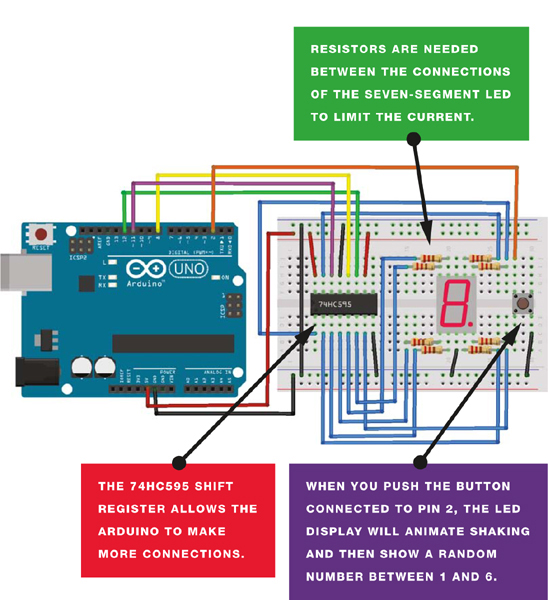
THE SKETCH
The sketch first sets the pins to control the 74HC595 chip that drives the seven-segment LED. When the seven-segment LED display is powered up, the dot is lit. When you press the pushbutton, the LEDs light in a short, rotating animation to signify that the die is shaking. After a moment a random number between 1 and 6 will be displayed. Press the button again to generate your next roll of the die.
// Code by Warrick A. Smith and reproduced with kind permission
// http://startingelectronics.com
const int latchPin = 8; // Pins connected to shift register
const int clockPin = 12;
const int dataPin = 11;
const int buttonPin = 2; // Pin connected to switch wire
// 1 to 6 and DP (decimal point) on 7-segment display
unsigned char lookup_7seg[] = {0x06, 0x5B, 0x4F, 0x66, 0x6D, 0x7D, 0x80};
// Shaking die pattern on 7-segment display
unsigned char shake_dice[] = {0x63, 0x5C};
// Rolling die on 7-segment display
unsigned char roll_dice[] = {0x1C, 0x58, 0x54, 0x4C};
// Vary duration of time before die number is received
int rand_seed;
int rand_num = 0; // Generate random number
unsigned char shake_toggle = 0; // For shaking dice animation
int index = 0; // For rolling dice animation
int shake_speed; // Accelerates dice shake speed
void setup() {
pinMode(latchPin, OUTPUT); // Output pins for controlling the
// shift register
pinMode(clockPin, OUTPUT);
pinMode(dataPin, OUTPUT);
pinMode(buttonPin, INPUT); // Read switch wire state
digitalWrite(latchPin, LOW); // Display DP on 7-segment display
// at startup
shiftOut(dataPin, clockPin, MSBFIRST, lookup_7seg[6]);
digitalWrite(latchPin, HIGH);
randomSeed(analogRead(0)); // Generate random seed
}
void loop() {
if (digitalRead(buttonPin)) {
shake_speed = 150; // Reset die shaking speed
delay(30);
// Generate number for random speed and show shaking animation
while (digitalRead(buttonPin)) {
rand_seed++; // Generate random number
// Animate shaking die
if (shake_toggle) {
AnimateDice(0, shake_dice);
shake_toggle = 0;
}
else {
AnimateDice(1, shake_dice);
shake_toggle = 1;
}
delay(80 + shake_speed); // Accelerate animation speed
if (shake_speed > 0) {
shake_speed -= 10;
}
}
// Animate rolling die
for (int rolls = 0; rolls < (rand_seed % 10 + 14); rolls++) {
AnimateDice(index, roll_dice);
delay((1 + rolls) * 20);
index++;
if (index > 3) {
index = 0;
}
}
rand_num = random(0, 6); // Generate number thrown on die
DiceNumber(rand_num);
}
}
// Display the die number on 7-segment display
void DiceNumber(unsigned char num) {
digitalWrite(latchPin, LOW);
shiftOut(dataPin, clockPin, MSBFIRST, lookup_7seg[num]);
digitalWrite(latchPin, HIGH);
}
// Display one frame of the shaking or rolling dice
void AnimateDice(int seg, unsigned char *table) {
digitalWrite(latchPin, LOW);
shiftOut(dataPin, clockPin, MSBFIRST, table[seg]);
digitalWrite(latchPin, HIGH);
}