
PROJECT 21: MOTION SENSOR ALARM
IN THIS PROJECT, WE’LL BUILD A MOTION-SENSING ALARM USING A PASSIVE INFRARED (PIR) SENSOR.
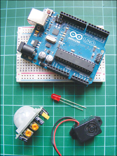
PARTS REQUIRED
• Arduino board
• Breadboard
• HC SR501 PIR sensor
• LED
• Piezo buzzer
You can use this alarm to trigger a variety of outputs, such as lights, motors, or even a “welcome home” message when you approach your front door.
HOW IT WORKS
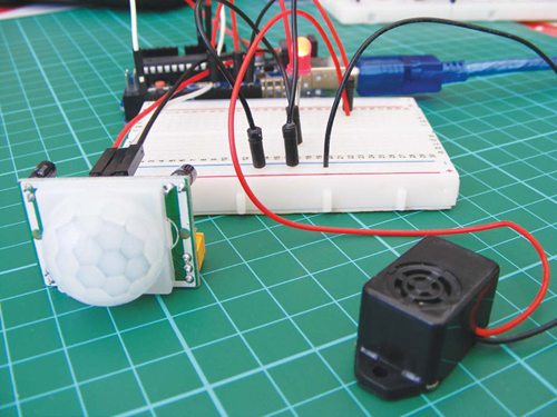
This project is based on the HC SR501 PIR sensor, which is widely available online for a few dollars. We’re going to set it up so that when someone passes in front of the PIR sensor, the LED will light up and the piezo buzzer will sound (see Figure 21-1), but you can adapt it for various other output.
FIGURE 21-1:
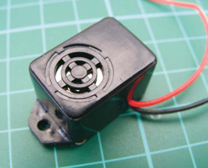
Any piezo buzzer will work for this project, but remember that most have polarity, so the red wire must be connected to +5V and the black wire to GND.
Other similar PIR sensors will work with this code, but it’s important to check the pin layout of your sensor on the data sheet, as this can vary. All sensors should have +5V, GND, and output pins. On this model, the pins are not clearly marked, but if you simply remove the outer lens (it’s clipped in place and can be unclipped easily), you can identify the pins underneath, as shown in Figure 21-2.
FIGURE 21-2:
A PIR sensor with the lens removed

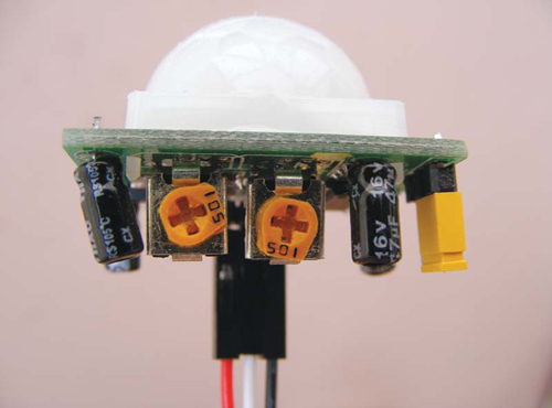
The two orange potentiometers on the sensor indicate that there are two adjustable settings. With the sensor upright, as shown in Figure 21-3, the left potentiometer controls how long the output is set to HIGH when something is detected, and can be set between 5 and 200 seconds. When we attach an LED to the output, the LED will be lit for between 5 and 200 seconds depending on the setting. The right potentiometer adjusts the detection range from 0 to 7 meters.
FIGURE 21-3:
PIR sensor potentiometers. The left controls how long the output is set to HIGH (5–200 seconds), while the right controls the range (0–7 meters).
The sensor works by detecting infrared radiation, which is emitted from objects that generate heat. Crystalline material within the sensor detects the infrared radiation, and when it detects a set level, it triggers the output signal of the sensor. The Arduino reads this output as voltage, so we can use this as a simple switch to turn something on—in this instance, an LED.
We are setting up the sensor so that an alarm sounds when the sensor is triggered, but there are other ways that you can customize the project. For example, you could scare your friends by attaching a servo and setting it up to release a rubber band when they walk by.
THE BUILD
Connect the PIR sensor’s +5V and GND wires to the +5V and GND rails on the breadboard, and connect these rails to the Arduino. Connect the PIR sensor’s output wire to Arduino pin 2. (See Figure 21-4.)
PIR SENSOR
ARDUINO
+5V
+5V
GND
GND
Output
Pin 2
FIGURE 21-4:
PIR sensor connected to wires
Insert an LED into the breadboard and connect the long, positive leg to Arduino pin 13, and the short, negative leg to GND. You don’t need a resistor for the LED in this project.
LED
ARDUINO
Positive leg
Pin 13
Negative leg
GND
Connect the piezo buzzer by attaching the red wire to Arduino pin 10 and the black wire to GND.
PIEZO
ARDUINO
Red wire
Pin 10
Black wire
GND
Confirm that your setup matches the circuit diagram in Figure 21-5, and then upload the code in “The Sketch” on page 183.
FIGURE 21-5:
The circuit diagram for the motion sensor alarm
THE SKETCH
The sketch works by setting Arduino pin 13 as output for the LED, pin 2 as input for the PIR sensor, and pin 10 as output for the piezo buzzer. When the PIR sensor is triggered, a HIGH signal is sent to the Arduino, which will in turn light the LED and play a tone on the piezo buzzer.
int ledPin = 13; // Pin connected to LED
int inputPin = 2; // Pin connected to PIR sensor
int pirState = LOW; // Start PIR state LOW with no motion
int val = 0; // Variable for reading the pin status
int pinSpeaker = 10; // Pin connected to piezo
void setup() {
pinMode(ledPin, OUTPUT); // Set LED as output
pinMode(inputPin, INPUT); // Set sensor as input
pinMode(pinSpeaker, OUTPUT);
Serial.begin(9600);
}
void loop() {
val = digitalRead(inputPin); // Read PIR input value
if (val == HIGH) { // Check if input is HIGH
digitalWrite(ledPin, HIGH); // If it is, turn ON LED
playTone(300, 160);
delay(150);
if (pirState == LOW) {
// Print to the Serial Monitor if motion detected
Serial.println("Motion detected!");
pirState = HIGH;
}
} else {
digitalWrite(ledPin, LOW); // If input is not HIGH,
// turn OFF LED
playTone(0, 0);
delay(300);
if (pirState == HIGH) {
Serial.println("Motion ended!");
pirState = LOW;
}
}
}
void playTone(long duration, int freq) { // Duration in ms,
// frequency in Hz
duration *= 1000;
int period = (1.0 / freq) * 1000000;
long elapsed_time = 0;
while (elapsed_time < duration) {
digitalWrite(pinSpeaker, HIGH);
delayMicroseconds(period / 2);
digitalWrite(pinSpeaker, LOW);
delayMicroseconds(period / 2);
elapsed_time += (period);
}
}