
PROJECT 10: JOYSTICK-CONTROLLED LASER
IN THIS PROJECT WE CREATE A JOYSTICK-CONTROLLED LASER BY CONNECTING TWO SERVOS TO A JOYSTICK AND USING THIS SETUP AS A PAN-AND-TILT CONTROLLER FOR A LASER POINTER.


PARTS REQUIRED
• Arduino
• Breadboard
• Jumper wires
• 2 Tower Pro SG90 9g servomotors
• Analog five-pin, two-axis joystick module
• Pan-and-tilt housing module
LIBRARIES REQUIRED
• Servo
HOW IT WORKS
Servos are small motors that can precisely angle their arms to positions between 0 and 180 degrees. In this project we’ll place the servos into a tilt-and-pan mount. The tilt-and-pan mount is a worthy investment, as it makes it much easier to attach the laser to the servo. Here we’re controlling a laser, but you could easily replace the laser with a webcam or another small device. We use two servos: one for left and right movement, and the other for up and down movement. As you might remember, servomotors have three wires, shown in Figure 10-1: positive power (red), negative power or ground (black or brown), and signal (typically yellow, orange, or white).
FIGURE 10-1:
Servos have three wires.

Before we begin building, you need to know a little about how a joystick works. The joystick shown in Figure 10-2 is basically two potentiometers and a button that allow us to measure the movement of the stick in two dimensions.
FIGURE 10-2:
This joystick has two potentiometers and a button for measuring movement.

Potentiometers are variable resistors and act as sensors that provide us with a voltage that varies depending on the rotation of the device around its shaft. So as you move the joystick around its center, its resistance—and therefore its output—varies. The outputs from the potentiometers are analog, so they can have a value only between 0 and 1,023 when read by the analog pin of the Arduino. This number sends a pulse to the Arduino, which in turn tells the servos how far to move. (See Project 2 for more on potentiometers.)
A joystick typically has five pins: VRx (the x-axis signal), VRy (the y-axis signal), SW (a pushbutton we won’t be using in this project), and GND and +5V for power.
When the x-axis of the joystick is moved to the left or right, the corresponding servo will move in that direction; when the y-axis of the joystick is moved up or down, the other servo will move up or down.
THE BUILD
Connect both servos’ red wires to the + 5V rail, and their brown wires to GND on the breadboard.
Connect one of the servo’s yellow signal wires directly to Arduino pin 9, and the other servo’s signal wire directly to Arduino pin 10, as shown in the circuit diagram in Figure 10-4.
SERVOS
ARDUINO
Red wires
+5V
Brown wires
GND
Yellow wire 1
Pin 9
Yellow wire 2
Pin 10
Connect the GND from the joystick module to the Arduino GND rail, and +5V to the Arduino +5V rail. Connect the VRx pin directly to Arduino A0, and the VRy pin directly to Arduino A1. Again, the SW switch connection is not used in this project.
JOYSTICK
ARDUINO
+5V
+5V
GND
GND
VRx
A0
VRy
A1
SW
Not used
Connect the breadboard rails to Arduino GND and +5V, and then check that your setup matches that of Figure 10-3.
FIGURE 10-3:
The circuit diagram for the joystick-controlled laser. Note that the joystick in this diagram is a different brand than the one used in the project, but the connections are the same, so the instructions in the project will work fine.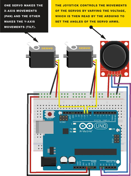
MOUNTING THE LASER
For this project, I’ve attached the servos to a pan-and-tilt housing module; you should be able to find this housing or a similar one for a relatively reasonable price on eBay by searching for “Arduino pan-and-tilt servo kit.” You may have to assemble it yourself, but this is simple to do with the included instructions.
Attach a laser diode to the top of the module; I recommend using a glue gun for a permanent fixture, but you can use tape if you want something more temporary. Now you can control the laser using the joystick. The servos will clip into the tilt-and-pan module as shown in Figure 10-5.
FIGURE 10-4:
Clipping the servos into the pan-and-tilt module

Moving the joystick left and right will move the x-axis servo, and moving the joystick up and down will move the y-axis servo. The complete assembly is shown in Figure 10-6.
FIGURE 10-5:
The complete assembly

THE SKETCH
The sketch first calls on the Servo library and then defines the two servos as tilt and pan. The joystick x-axis is attached to Arduino pin A0 and the y-axis to Arduino A1, and these are our INPUT. The x- and y-axes are then set as variables for movement. The tilt servo is attached to Arduino pin 9 and pan is attached to Arduino pin 10, and these are our OUTPUT. The Arduino then reads the INPUT from the joystick and changes this voltage to OUTPUT, moving the servos according to which direction is chosen.
// Used with kind permission from http://learn.explorelabs.com/
// Creative Commons 4.0 Share Alike (CC by SA 4.0) license
#include <Servo.h>
Servo tilt, pan; // Create servo object
int joyX = A0; // Analog pin connected to x-axis servo
int joyY = A1; // Analog pin connected to y-axis servo
int x, y; // Variables to read values
void setup() {
tilt.attach(9); // Attach tilt servo on pin 9 to the servo object
pan.attach(10); // Attach pan servo on pin 10 to the servo object
}
void loop() {
x = joyX; // Read value of x-axis (between 0 and 1023)
y = joyY; // Read value of y-axis (between 0 and 1023)
x = map(analogRead(joyX), 0, 1023, 900, 2100); // Scale it to use
// with servo between
// 900 to 2100
// microseconds
y = map(analogRead(joyY), 0, 1023, 900, 2100);
tilt.write(x); // Set servo position according to scaled value
pan.write(y);
delay(15); // Wait for servos to get to new position
}