PROJECT 5: PLANT MONITOR
IN THIS PROJECT I’LL INTRODUCE A NEW TYPE OF ANALOG SENSOR THAT DETECTS MOISTURE LEVELS. YOU’LL SET UP A LIGHT AND SOUND ALARM SYSTEM TO TELL YOU WHEN YOUR PLANT NEEDS WATERING.


PARTS REQUIRED
• Arduino board
• Jumper wires
• LED
• HL-69 hygrometer soil moisture sensor
• Piezo buzzer
HOW IT WORKS
You’ll use an HL-69 moisture sensor, readily available online for a few dollars or from some of the retailers listed in Appendix A. The prongs of the sensor detect the moisture level in the surrounding soil by passing current through the soil and measuring the resistance. Damp soil conducts electricity easily, so it provides lower resistance, while dry soil conducts poorly and has a higher resistance.
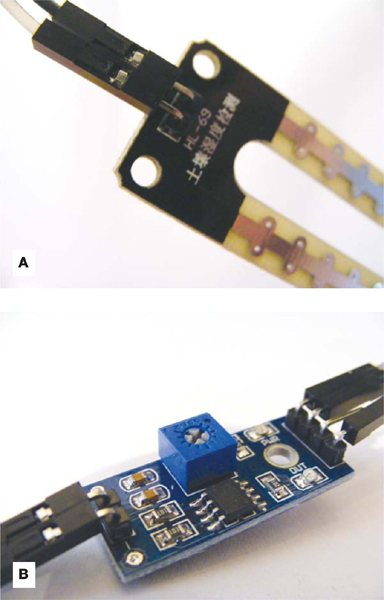
The sensor consists of two parts, as shown in Figure 5-1: the actual prong sensor (a) and the controller (b). The two pins on the sensor need to connect to the two separate pins on the controller (connecting wires are usually supplied). The other side of the controller has four pins, three of which connect to the Arduino.
FIGURE 5-1:
The HL-69 moisture sensor prong (a) and controller (b)
The four pins are, from left to right, AO (analog out), DO (digital out), GND, and VCC (see Figure 5-2). You can read the values from the controller through the IDE when it’s connected to your computer. This project doesn’t use a breadboard, so the connections are all made directly to the Arduino.
FIGURE 5-2:
The pins are labeled on the underside of the module

Lower readings indicate that more moisture is being detected, and higher readings indicate dryness. If your reading is above 900, your plant is seriously thirsty. If your plant gets too thirsty, the LED will light and the piezo buzzer will sound. Piezos are inexpensive buzzers and are explained more in Project 7.
THE BUILD
Connect the sensor’s two pins to the + and – pins on the controller using the provided connecting wires, as shown in Figure 5-3.
FIGURE 5-3:
Connecting the sensor to the controller
Connect the three prongs from the controller to +5V, GND, and Arduino A0 directly on the Arduino, as shown in the following table. The DO pin is not used.
SENSOR CONTROLLER
ARDUINO
VCC
+5V
GND
GND
A0
A0
DO
Not used
Connect an LED directly to the Arduino with the shorter, negative leg in GND and the longer, positive leg in Arduino pin 13, as shown in Figure 5-4.
FIGURE 5-4:
Connecting the LED to the Arduino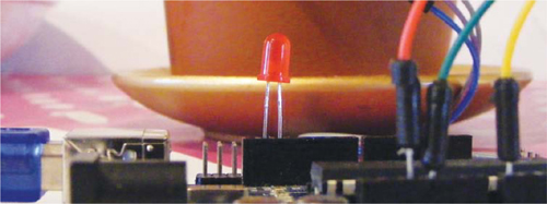
LED
ARDUINO
Positive leg
Pin 13
Negative leg
GND
Connect the piezo buzzer’s black wire to GND and its red wire to Arduino pin 11.
PIEZO
ARDUINO
Red wire
Pin 11
Black wire
GND
Check that your setup matches that of Figure 5-5, and then upload the code in “The Sketch” on page 51.
FIGURE 5-5:
Circuit diagram for the plant monitor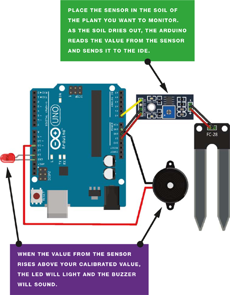
Connect the Arduino to your computer using the USB cable. Open the Serial Monitor in your IDE to see the values from the sensor—this will also help you to calibrate your plant monitor. The IDE will display the value of the sensor’s reading. My value was 1000 with the sensor dry and not inserted in the soil, so I know this is the highest, and driest, value. To calibrate this value, turn the potentiometer on the controller clockwise to increase the resistance and counterclockwise to decrease it (see Figure 5-5).
When the sensor is inserted into moist soil, the value will drop to about 400. As the soil dries out, the sensor value rises; when it reaches 900, the LED will light and the buzzer will sound.
FIGURE 5-6:
Turn the potentiometer to calibrate your plant monitor.
THE SKETCH
The sketch first defines Arduino pin A0 so that it reads the moisture sensor value. It then defines Arduino pin 11 as output for the buzzer, and pin 13 as output for the LED. Use the Serial.Println() function to send the reading from the sensor to the IDE, in order to see the value on the screen.
Change the value in the line
if(analogRead(0) > 900){
depending on the reading from the sensor when it is dry (here it’s 900). When the soil is moist, this value will be below 900, so the LED and buzzer will remain off. When the value rises above 900, it means the soil is drying out, and the buzzer and LED will alert you to water your plant.
const int moistureAO = 0;
int AO = 0; // Pin connected to A0 on the controller
int tmp = 0; // Value of the analog pin
int buzzPin = 11; // Pin connected to the piezo buzzer
int LED = 13; // Pin connected to the LED
void setup () {
Serial.begin(9600); // Send Arduino reading to IDE
Serial.println("Soil moisture sensor");
pinMode(moistureAO, INPUT);
pinMode(buzzPin, OUTPUT); // Set pin as output
pinMode(LED, OUTPUT); // Set pin as output
}
void loop () {
tmp = analogRead( moistureAO );
if ( tmp != AO ) {
AO = tmp;
Serial.print("A = "); // Show the resistance value of the sensor
// in the IDE
Serial.println(AO);
}
delay (1000);
if (analogRead(0) > 900) { // If the reading is higher than 900,
digitalWrite(buzzPin, HIGH); // the buzzer will sound
digitalWrite(LED, HIGH); // and the LED will light
delay(1000); // Wait for 1 second
digitalWrite(buzzPin, LOW);
digitalWrite(LED, HIGH);
}
else {
digitalWrite(buzzPin, LOW); // If the reading is below 900,
// the buzzer and LED stay off
digitalWrite(LED, LOW);
}
}