
It's now the time to assemble the hardware for the project. We'll first connect the Adafruit FONA shield and then the other components. Before assembling the hardware, make sure that you have inserted the SIM card into the FONA shield.
The following is a schematic to help you out:
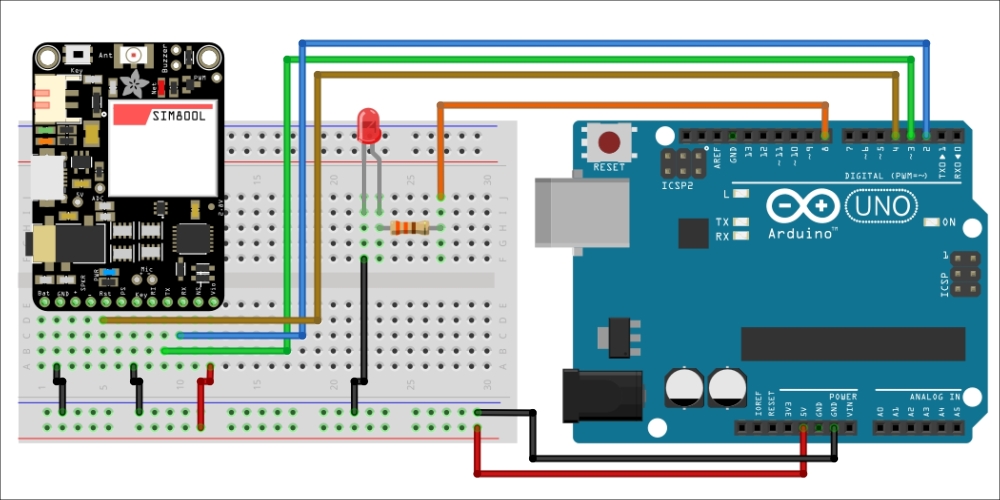
Note that the location of the pins can be different on your FONA shield, as there are many versions available. Also, note that the relay is not represented on this schematic. Here are the steps that you need to take in order to assemble the hardware:
- First, connect the power supply to the breadboard. Connect the 5V pin from the Arduino board to the red power line on the breadboard and the GND pin to the blue power line.
- Then, place the FONA shield on the breadboard. Connect the VIO pin to the red power line and the GND and key pins to the blue power line.
- After that, connect the RST pin to Arduino pin 4, TX to Arduino pin 3, and RX to Arduino pin 2. Also, connect the 3.7V LiPo battery and antenna to the FONA shield.
- Finally, connect the relay and the LED to the Arduino board. Connect the relay VCC and GND pin to the power supply on the breadboard and the EN pin to pin 7 of the Arduino board.
- For the LED, place it in series with a 330 Ohm resistor on the breadboard, with the longest side of the LED connected to the resistor. Then, connect the other pin of the resistor to pin 8 of the Arduino board. Also, connect the other pin of the LED to the ground.
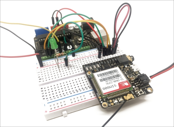
The following is an image of the completed project, with a zoom around the FONA shield and Arduino board:
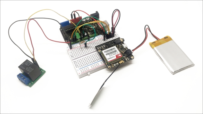
The following is an overview of the completely assembled project:
..................Content has been hidden....................
You can't read the all page of ebook, please click here login for view all page.