
Now let's assemble the different components of this project. This is a schematic to help you out:
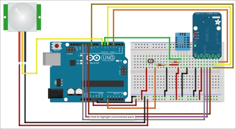
First, connect the power. Connect the Arduino Uno 5V to the red power rail on the breadboard, and the GND pin to the blue power rail. Also, place all the main components on the breadboard.
After that, for the DHT11 sensor, follow the instructions given by the schematic to connect the sensor to the Arduino board. Make sure you don't forget the 4.7k Ohm resistor between the VCC and signal pins.
We are now going to connect the photocell. Start by placing the photocell on the breadboard in series with the 10k Ohm resistor. After that, connect the other end of the photocell to the red power rail, and the other pin of the resistor to the blue power rail. Finally, connect the pin between the photocell and the resistor to Arduino Uno pin A0.
Finally, for the motion sensor, connect the VCC pin to the red power rail, the GND pin to the blue power rail, and finally the output pin of the sensor to Arduino pin 7.
Now, we are going to connect the CC3000 breakout board. Connect the pins as indicated on the schematic: IRQ to pin number 3 of the Arduino board, VBAT to pin 5, and CS to pin 10. After that, connect these pins to the Arduino board: MOSI, MISO, and CLK go to pins 11, 12, and 13, respectively. Finally, connect the power to the CC3000 breakout: connect 5V to the Vin pin of the breakout board, and GND to GND.
This is a picture of the completely assembled project:
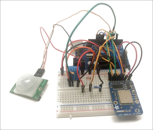
Congratulations, your project is now fully assembled! You can move on to the next part: sending data to the cloud.