
CHAPTER 14
Using Layouts to Set Up a Print
A design is only as good as your ability to communicate that design with the people building it. Printing, or plotting as it's called in Autodesk® AutoCAD® software, is considered by many to be the final phase of that communication process. Preparing a document set can be just as challenging as plotting it.
In this chapter, you will set up sheet files in a way that maximizes the potential of layers and external references. You will learn to further automate the management of your drawing sheets by using Sheet Set Manager.
As you work through this and the next chapter, you'll quickly discover the incredible control you have over nearly every aspect of how a drawing plots. This versatility means you can probably get AutoCAD to plot exactly the way you want it to. However, remembering each of those settings can prove challenging. Consequently, the key to getting consistent plots is to find a way to capture all of those settings in a way that will allow you to reuse them for new drawings in the future.
This chapter strives to employ the most widely accepted practices with a specific focus on capturing settings so that they can be reused later. To get to a point where you can begin plotting, you will apply the knowledge you've gained from numerous chapters throughout this book, including Chapter 6 (“Using Layers to Organize Your Drawing”), Chapter 9 (“Using Dynamic Blocks and Tables”), and Chapter 13 (“Managing External References”).
In this chapter, you will learn to
- Put a title block in a layout
- Set up viewports in a layout
- Lock the display of viewports
- Control visibility in viewports
- Add text in a layout
Getting Ready
So far, all of your work has been done in model space. There you drew your cabin by using real-world units, meaning that if a wall was 6″, you drew the wall at 6′. It's certainly not possible to print the cabin using real-world units. Instead, you need to somehow reduce its size. This is where a list of standard scales used by architects and engineers, such as ![]() or
or ![]() (or 1 = 50), comes into play.
(or 1 = 50), comes into play.
The standard way of accomplishing this is with layout tabs, sometimes referred to by their former name of paper space. Each layout is assigned a printer and paper size, and you adjust the positioning of the drawing and the scale of the print. The part that is difficult to understand is the way that two scales are juxtaposed in the same file: the scale of the drawing on the printed paper (usually a standard scale used by architects, such as ![]() or
or ![]() or 1 = 50), and the scale of the layout, which is almost always 1:1, or the actual size of the paper. Other professionals, such as mechanical or civil engineers, set up their drawings the same way. They may use a different set of standard scales such as 1″ = 30′ for the drawing, but the layout almost always remains 1:1.
or 1 = 50), and the scale of the layout, which is almost always 1:1, or the actual size of the paper. Other professionals, such as mechanical or civil engineers, set up their drawings the same way. They may use a different set of standard scales such as 1″ = 30′ for the drawing, but the layout almost always remains 1:1.
One way to visualize how layouts—and more specifically, viewports—work is to think about looking through a pair of binoculars. By turning one knob, you can adjust how big or small objects appear, by changing the magnification or scale of the current view. Turning a second knob allows you to adjust how the view is focused—or, in the context of AutoCAD, which layers and drawings are viewable and which ones are not. Finally, moving (panning) to the left or right completely changes everything in the current view.
Another way to visualize how a layout works is to think of it as a second drawing, or a specialized layer, that has been laid over the top of your current drawing. Each layout that you create will have one or more viewports—special windows through which you will view your project at a scale to be printed. The layouts are usually at a scale of 1:1 (actual size), and they contain some of the information that you originally included with the building lines, such as the border and title block, notes, scale, North arrow, and so on.
Think for a moment about drawing the floor plan of a building on a traditional drafting table. You draw the building to a scale such as ![]() (1 = 50). Then, on the same sheet of paper, you print a note using letters that are, say,
(1 = 50). Then, on the same sheet of paper, you print a note using letters that are, say, ![]() (3.5 mm) high. If you looked at those letters as being on the same scale as the building, they would measure 6″ (175 mm) high, and that's what we've been doing on the cabin drawing so far. But in traditional drafting, you don't think that way. Instead, you work with two scales in the drawing without thinking about it. So a letter is
(3.5 mm) high. If you looked at those letters as being on the same scale as the building, they would measure 6″ (175 mm) high, and that's what we've been doing on the cabin drawing so far. But in traditional drafting, you don't think that way. Instead, you work with two scales in the drawing without thinking about it. So a letter is ![]() (3.5 mm) high (actual size), and a part of the building that measures
(3.5 mm) high (actual size), and a part of the building that measures ![]() (3.5 mm) on the paper is thought of as being 6″ (175 mm) long at a scale of
(3.5 mm) on the paper is thought of as being 6″ (175 mm) long at a scale of ![]() (1 = 50). Layouts are designed to let you juggle two or more scales in a drawing in the same way in order to set up the drawing to be printed.
(1 = 50). Layouts are designed to let you juggle two or more scales in a drawing in the same way in order to set up the drawing to be printed.
Preparing the Title Block
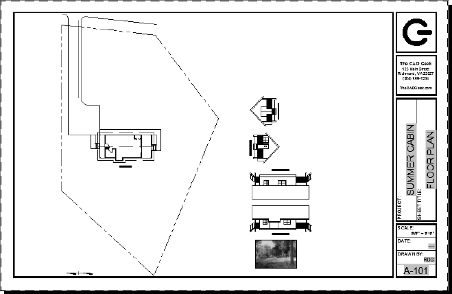
In Chapter 8, “Controlling Text in a Drawing,” you created the title block or border for your cabin. As you may recall, you had to draw the title block much larger than the intended plot size of ![]() to fit the entire cabin on the sheet. Since layout tabs always have a standard paper size such as
to fit the entire cabin on the sheet. Since layout tabs always have a standard paper size such as ![]() (A4210 mm×297 mm) assigned, you will need to make a 1:1 version of the title block. Doing this will give you a single reference drawing that will be used as the foundation for each of your plan sheets.
(A4210 mm×297 mm) assigned, you will need to make a 1:1 version of the title block. Doing this will give you a single reference drawing that will be used as the foundation for each of your plan sheets.
Creating the Title Block Reference
You certainly don't want to waste the time you invested in creating the title block for your cabin in Chapter 8. Therefore, while the primary focus of this section is to create a usable title block reference, the secondary focus is to preserve as much of the work you've already done as possible. This will be accomplished by using some commands with which you're already familiar.
To define your title block reference, take the following steps:
- Open the I13A-FPLAYO.dwg (M13A-FPLAYO.dwg) file you created in the previous chapter, or from this chapter's download site found at www.sybex.com/go/autocad2013ner or www.thecadgeek.com.
- Turn on the title block layers A-ANNO-TTLB and A-ANNO-TTLB-TEXT by using the LAYER command.
- Close or collapse the Layer Properties Manager palette when you're finished.
- Start the BLOCK command by using the Create Block tool on the Block Definition panel of the Insert tab.
- From the Block Definition dialog box, enter TTLB-1117 (TTLB-A3) for the block's name.
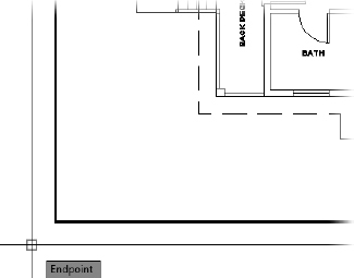
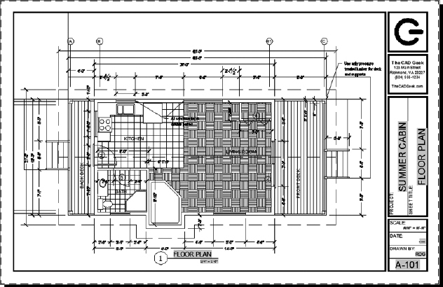
 Click the Pick Insertion Base Point button, and pick the endpoint in the lower-left corner of the outer boundary shown in Figure 14.1.
FIGURE 14.1 Choosing the base point for the title block
You have already used the BLOCK command to select objects manually in your drawing. Another way of selecting objects is to use the Quick Select option to select objects based on a common property.
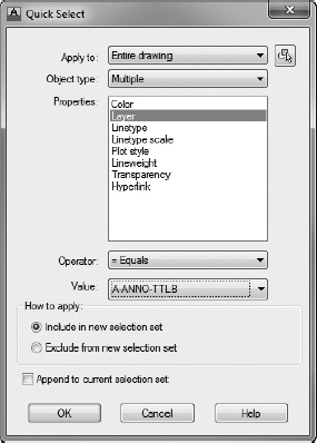
 Click the Quick Select button, found in the Objects group of the Block Definition dialog box, to open the Quick Select dialog box shown in Figure 14.2.
FIGURE 14.2 Filtering title block layers by using the Quick Select dialog box
The Quick Select dialog box can be used to select any number of objects based on a common property. This property can be anything from the type of object to all of the circles with a certain linetype. You will use the Quick Select dialog box to find all objects on the A-ANNO-TTLB layers.
- Using Figure 14.2 as your guide, verify that Apply To is set to Entire Drawing and that Object Type is set to Multiple.
The Properties combo box updates to list all of the available properties.
The options found in the Properties combo box will depend on the Object Type setting you have selected.
- Select the Layer property and then do the following:
- Verify that Operator is set to Equals.
- Use the Value drop-down list to select the A-ANNO-TTLB layer.
- Click OK to return to the Block Definition dialog box.
You'll see that the number of objects selected has also updated to reflect the number of objects on the A-ANNO-TTLB layer.
- Repeat steps 7 to 10, but this time do this:
- Select A-ANNO-TTLB-TEXT from the Value drop-down list.
- Make sure Append To Current Selection Set is checked in the Quick Select dialog box.
The number of selected objects is updated once again. This time, the value is a combination of the number of objects on both the A-ANNO-TTLB and A-ANNO-TTLB-TEXT layers.
- Pick the Delete option under the Objects heading, and then check the Open In Block Editor option in the lower-left corner before clicking the OK button.
The Block Editor opens with the newly created TTLB-1117 (TTLB-A3) block, which you will scale down to its actual 11″×17″ (297 mm×420 mm) size.
- Start the SCALE command and then do this:
- Select the entire title block.
- Pick the lower-right corner of the interior boundary as the base point.
- Instead of entering a scale factor, do this:
- Press R
 to choose the Reference option.
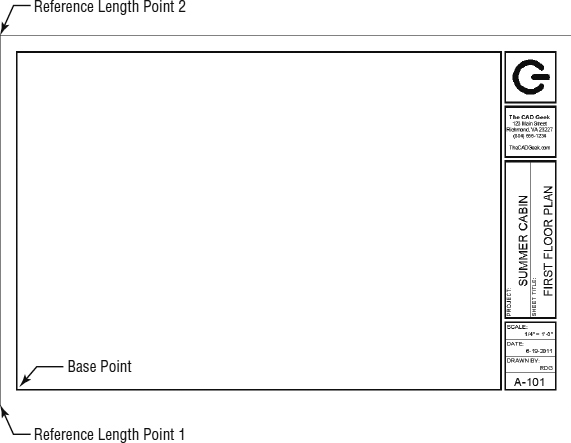
 - Pick the lower-left corner of the outer boundary and then the upper-left corner of the outer boundary (see Figure 14.3).
FIGURE 14.3 Specifying a reference length by using the SCALE command
- Press R
- After choosing the points to define the reference length, enter 11 (297) to scale your title block to the exact height of 11″ (297 mm).
You may need to perform a Zoom Extents to bring the title block back into view.
- Click the Save Block button on the Open/Save panel of the Block Editor tab.
- Exit the Block Editor by clicking the Close Block Editor button on the Close panel.
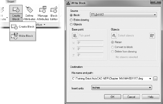
- Start the Write Block (WBLOCK) command by expanding the Create Block tool on the Insert tab
 Block Definition panel (see the left image in Figure 14.4).
The Write Block dialog box, shown on the right in Figure 14.4, opens.
FIGURE 14.4 Starting the Write Block command (left) and the Write Block dialog box (right)
- Within the Write Block dialog box, choose Block as the Source setting and select the TTLB-1117 (TTLB-A3) block from the drop-down list.
- Finally, click the ellipsis button at the end of the File Name And Path text box to create a file named I14-01-A-BD1117.dwg (M14-01-A-BDA3.dwg) in your Chapter 14 Training Data directory.
- Verify that your Write Block dialog box looks like the right side of Figure 14.4, and click OK to finish the command.
- Save the drawing I13A-FPLAYO.dwg (M13A-FPLAYO.dwg) as I14A-FPLAYO.dwg (M14A-FPLAYO.dwg), and close it.
You have now extracted the title block out of your floor plan layout drawing and created a new drawing with nothing but the title block. The construction document, sometimes called the CD set, will use the common 11″×17″ (297 mm×420 mm), or A3, sheet size, corresponding to the title block you drew in Chapter 8. To make your title block usable for any drawing sheet, you'll continue refining your title block reference by adding block attributes in the next exercise.
Defining the Attributes
Instead of starting from scratch, you'll use the title block reference you already have as the foundation for your sheet information block. The following exercise will guide you through the process of creating attributes from the existing text in the title block drawing:
- Open I14-01-A-BD1117.dwg (M14-01-A-BDA3.dwg) from the Training Data directory if it isn't already open.
- From the Insert tab Block Definition panel, select the Define Attributes button to open the Attribute Definition dialog box.
You will create attribute definitions as you did in Chapter 9, except this time you'll focus more on text justification than text style. After all of the attributes are defined, you'll learn how to use the existing text as a template for style by using the MATCHPROP (Match Properties) command.
- For the first attribute, enter PROJECT for the Tag and Enter Project Name for the Prompt.
Sheet Set Manager is an extensive feature set that helps you manage the drawings that make up your project. It is discussed a little later in this chapter, but for now you'll simply set up your sheet information block so that it can use some of these advanced features.
 Click the Insert Field button found next to the Default text box in the Attribute Definition dialog box.
- Select the Field Category drop-down list, and then pick the SheetSet option.
This filters the list of available Field Names to include only those pertaining to Sheet Set Manager.
- Choose CurrentSheetSetProjectName from the list of available Field Names, and then pick Uppercase from the Format list on the right.
The Field dialog box should look like Figure 14.5.
- Click OK to exit the Field dialog box.
 NOTE Design drawings typically use uppercase letters, especially when prominent items such as titles are designated.
Back in the Attribute Definition dialog box, the Default field now contains #### and has a gray background, as shown in Figure 14.6.
- Under the Text Settings group, enter the following settings:
- Set the Justification to Bottom Center.
- Set Text Style to Standard, and set Rotation to 90°
- Enter an arbitrary text height, such as
 (3.5 mm).
With your settings matching those illustrated in Figure 14.6, click OK.
- Use the Insertion osnap to place the PROJECT attribute on top of the existing SUMMER CABIN text string.
FIGURE 14.5 Selecting the Sheet Set Manager project name from the Field dialog box
FIGURE 14.6 The Attribute Definition with a field set as the Default value
 Select the Match Properties button on the Clipboard panel on the Home tab, or enter MP to start the MATCHPROP command.
- With Match Properties running, select the SUMMER CABIN text string as the source object (see the top image of Figure 14.7), and then select the PROJECT attribute definition as the destination object (see the bottom image of Figure 14.7).
FIGURE 14.7 Matching the properties of the SUMMER CABIN text string with the PROJECT attribute definition
- Erase the SUMMER CABIN text string to leave the PROJECT attribute definition in its place.
- Repeat steps 2 to 12 to create attribute definitions for the SHEET_TITLE, SCALE, DATE, DRAWN BY, and SHEET NUMBER blocks. Replace the parameters for the PROJECT attribute definition with the following:
- SHEET TITLE
Tag: SHEET_TITLE
Prompt: Enter Sheet Title
Default: Select the Uppercase CurrentSheetTitle Field under the SheetSet Field Category.
Justification: Bottom Center
Rotation: 90°
- SCALE
Tag: DRAWING_SCALE
Prompt: Enter Drawing Scale
Default: #″ = #′-#″ (# : ##)
Justification: Bottom Right
- DATE
Tag: DATE
Prompt: Enter Date Drawn
Default: Select the CurrentSheetRevisionDate under the SheetSet Field Category.
Justification: Bottom Right
- DRAWN BY
Tag: DRAWN_BY
Prompt: Enter Drafter's Initials
Default: Select the Uppercase Author Field under the Document Field Category.
Justification: Bottom Right
- SHEET NUMBER
Tag: SHEET_NO
Prompt: Enter Sheet Number
Default: Select the Uppercase CurrentSheetNumber Field under the SheetSet Field Category.
Justification: Middle Center
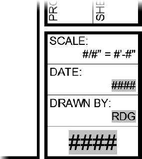
Adjust the position of the DRAWN_BY and DATE attributes as needed. The title block should look like Figure 14.8.
- SHEET TITLE
- Save your drawing as I14-02-A-BD1117.dwg (M14-02-A-BDA3.dwg).
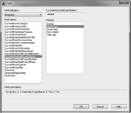
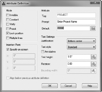
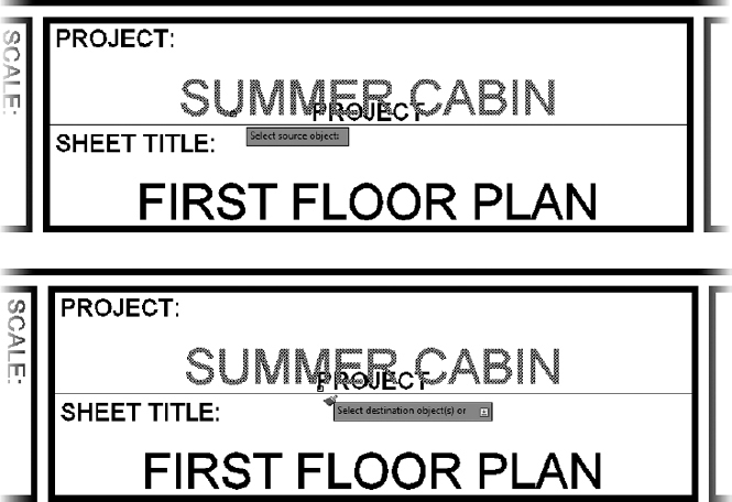

FIGURE 14.8 Text strings replaced with attribute definitions
Instead of static text strings, the title block now has a series of attributes that will make changing—and more important, managing—the variable data within your title block easier. Later in this chapter, you will create plan sheets by using the XREF command to insert the title block into each plan sheet.
Making the Sheet Information Block
Although blocks and xrefs share some properties and behaviors, xrefs cannot be used to manage attributes. Consequently, in addition to the I14-02-A-BD1117.dwg (M14-02-A-BDA3.dwg) file that you have already created, you will also need to create a sheet information block containing your attribute definitions, which will then be inserted into each drawing in your plan set. Use the WBLOCK command to extract the attributes from the title block drawing by doing the following:
- Open I14-02-A-BD1117.dwg (M14-02-A-BDA3.dwg) from the Training Data directory if it isn't already open.
- Select each of the attribute definitions, and change the layer to Layer 0 and the Color to ByBlock.
- Choose Write Block from the Insert tab Block Definition panel, or enter WBLOCK at the command line to open the Write Block dialog box.
- In the Write Block dialog box, set the following:
- Source to Objects
- Base Point to 0,0,0
- Objects to Delete From Drawing
- Click the Select Objects button within the Objects group to return to the drawing.
When creating attribute blocks, the order in which you select the attributes will dictate the order AutoCAD will use to prompt you when inserting the block. Therefore, it's important to select attributes individually, not using one of the window section methods.
- Select the attributes in the following order:
- SHEET_NO
- SHEET_TITLE, PROJECT
- DRAWING_SCALE, DRAWN_BY
- DATE
- Press after you finish selecting the attributes.
- Back in the Write Block dialog box, click the ellipsis button at the end of the File Name And Path text box to save this block as TTLB-INFO in the Chapter 14 Training Data folder.
When you're finished, the Write Block dialog box should look like Figure 14.9.
- Click the OK button to create the I-TTLB-INFO.dwg (M-TTLB-INFO.dwg) file.
- Save your drawing as I14A-BD1117.dwg (M14A-BDA3.dwg).
When the Write Block dialog box closes, you'll be taken back to the drawing, where you'll see that the block attributes are no longer in the drawing.
![]() NOTE Notice how the block labels, such as PROJECT: and DRAWN BY: remain in the drawing. These entities have been kept in the title block reference because they are unlikely to change—and even if they did, they would be the same in every sheet throughout the project. If we hadn't planned to use Sheet Set Manager, you might have chosen to keep the project name in the title block reference as well.
NOTE Notice how the block labels, such as PROJECT: and DRAWN BY: remain in the drawing. These entities have been kept in the title block reference because they are unlikely to change—and even if they did, they would be the same in every sheet throughout the project. If we hadn't planned to use Sheet Set Manager, you might have chosen to keep the project name in the title block reference as well.
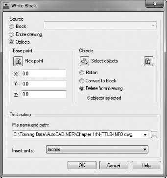
FIGURE 14.9 Defining the TTLB-INFO block unit in the Write Block dialog box
Setting Up a Sheet Template
As mentioned in the introduction to this chapter, you have considerable control over the way your drawings are plotted. The trade-off for this degree of granularity is that you have a large number of settings to manage. Keeping all of these settings at consistent values throughout a plan set can be rather challenging. One of the best ways to ensure that your entire plan set is configured exactly the same way is to start with a template. By creating a template of a typical plan sheet, you can then create subsequent plan sheets from it, which in turn copies all of the plot settings.
This section focuses on the creation of a sheet template that you'll use later in this chapter to create your plan sheets:
- Create a directory named Sheets in your Chapter 14 directory.
This directory will be used to store each of the plan sheets.
- To begin creating your plan sheet template, create a new drawing by choosing Application menu New Drawing.
- Use the down-arrow next to the Open button to select Open With No Template - Imperial (Open With No Template - Metric).
Before creating a new layout, you should set the AutoCAD interface to display the layouts easily.
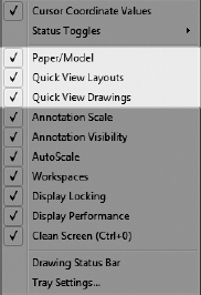
- Right-click an empty area on the status bar, and ensure that Paper/Model, Quick View Layouts, and Quick View Drawings each has a check mark next to it, as shown in Figure 14.10.
FIGURE 14.10 Turn on the Paper/Model and Quick View options in the context menu.

The Model or Paper Space, Quick View Layouts, and Quick View Drawings buttons appear in the middle of the status bar. By clicking these buttons, you can quickly switch between displaying a layout and looking at model space, which is the way you have been using AutoCAD up to this point.
Each layout has settings that spell out which plotting device is to be used to print the layout and how the print will appear. You specify these settings through a page setup that becomes associated with the layout.
NOTE I use the terms print and plot interchangeably in this book, as I do printer and plotter. In the past, plot and plotter referred to large-format devices and media, but that's not necessarily true today. Print and printer are more widely used now because of changes in the technology of the large-format devices.  Click the Model button in the status bar to switch from model space to view the drawing through the layout.
The appearance of the drawing area changes to show a view into model space inside a white rectangle sitting in front of a gray background.
Your drawing has two borders along the perimeter of the white rectangle (one dashed and one solid).
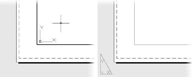
- If the UCS icon consists of two arrows inside the solid border (see the left of Figure 14.11), then you are currently working in model space.
FIGURE 14.11 The layout in model space (left) and in paper space (right)
- If the UCS icon is shaped like a triangle and located in a portion of the drawing area (see the right of Figure 14.11), then you are currently working in paper space.
The solid line is the boundary to the viewport, and the dashed line is the limit of the printable area.
- If the UCS icon consists of two arrows inside the solid border (see the left of Figure 14.11), then you are currently working in model space.
![]() TIP You can switch back to paper space when working in model space by moving your cursor outside of the inner, solid rectangle and double-clicking, or by entering PS
TIP You can switch back to paper space when working in model space by moving your cursor outside of the inner, solid rectangle and double-clicking, or by entering PS![]() .
.
Setting the Layout Parameters
The paper shown—that is, the white rectangle—is the default size and orientation for the acad.dwt template. You'll need to set the parameters to utilize the DWFx ePlot plotter (installed with AutoCAD).
 Click the Quick View Layouts button next to the Layout button in the status bar to turn on the option.
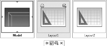
Small thumbnail representations of the existing layouts appear at the bottom of the drawing area, as shown in Figure 14.12.
FIGURE 14.12 The drawing's layouts shown by using the Quick View Layouts tool
- Place the cursor over the Layoutl thumbnail.
It turns blue, and two icons appear within its frame to indicate that any changes will affect that layout only.
- Right-click and then select the Page Setup Manager option in the context menu.
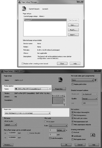
After a moment, the Page Setup Manager dialog box opens (see the top of Figure 14.13). This is where you create a new page setup, or assign an existing one, to be associated with a new or selected layout.
- Click New to open the New Page Setup dialog box.
- In the New Page Setup Name text box, enter DWFX-1117 (DWFX-A3) and click OK.
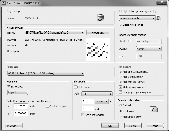
This opens the Page Setup dialog box, which has DWFX-1117 (DWFX-A3) added to the title bar (see the bottom of Figure 14.13). The DWFX-1117 (DWFX-A3) name also appears toward the top of the dialog box in the Page Setup group. In all, the dialog box has 10 groups containing settings that control how the drawing will fit on the printed page and what part of the drawing is printed.
NOTE This chapter is designed so that you can follow along even if you don't have a printer hooked up to your computer. The plotter used by this book is one that installs with AutoCAD and creates an electronic file with a .dwfx extension. DWF is a format similar to PDF that was defined by Autodesk for the purpose of electronically storing, sharing, and illustrating design drawings.If you have not created a page setup previously, None will be selected. By default, the Printer/Plotter Name drop-down list also lists all of the plotters (printers) installed on your computer.
FIGURE 14.13 The Page Setup Manager dialog box (top) and the Page Setup dialog box (bottom)
- Select the DWFx ePlot (XPS Compatible).pc3 plotter from the Printer/Plotter Name drop-down list.
In the Printer/Plotter group, DWFx ePlot (XPS Compatible).pc3 is the selected plotter.
- From the drop-down list in the Paper Size group, select ANSI Full Bleed B (17.00 × 11.00 Inches) or ISO Full Bleed A3 (420.00 × 297.00 mm).
Because each printer/plotter will likely have slightly different page sizes, it's best to select the plotter first and the paper size second.
- With both the plotter and paper size selected, complete your page setup by setting the following parameters:
- Plot Area
What to plot: Layout
- Plot Scale
Scale: 1:1
Units: Inches (mm)
 TIP The Scale drop-down list contains several preset scales and a Custom option. To delete unnecessary scales, add new ones, edit existing ones, or rearrange the order of the listing, use the Ribbon to choose Annotate tab Annotation Scaling panel Scale List tool, use the menu bar to choose Format Scale List, or enter SCALELISTEDIT at the command line to open the Edit Drawing Scales dialog box.
 - Plot Style Table (Pen Assignments)
Plot Style Table: monochrome.ctb
Display Plot Styles: Checked
- Drawing Orientation
Landscape: Selected
When finished, the Page Setup - DWFX-1117 (Page Setup - DWFX-A3) dialog box should look like Figure 14.14.
- Plot Area
- Click OK. You are returned to the Page Setup Manager dialog box.
DWFX-1117 (DWFX-A3) is now on the Page Setups list.
- Highlight DWFX-1117 (DWFX-A3), and then click Set Current.
The layout area behind the dialog box changes to match the parameters you set in the Page Setup dialog box.
- Click Close to close the Page Setup Manager dialog box.
You are returned to your drawing, and Layout1 appears (see Figure 14.15).
FIGURE 14.14 The completed page setup
FIGURE 14.15 The named page setup applied to Layout1 for the cabin
You don't want the current viewport, the window that lets you see your drawing from the layout. You will make your own shortly.
- Make sure that you're in paper space, and then enter E ALL to select all the objects in the layout.
In the command window, you can see that only the viewport is selected.
- Press to erase the viewport.
- Click the Quick View Layouts button once again, this time to right-click Layout2.
- To remove Layout2 from the current drawing, choose Delete from the contextual menu that appears.
- Save the current drawing as an AutoCAD drawing template by choosing Application menu Save As AutoCAD Drawing Template. Browse to the root of your Chapter 14 directory, and save the drawing as I14A-BDTPLT.dwt (M14A-BDTPLT.dwt).
- When the Template Options dialog box opens, enter Title block layout template, select English (Imperial) or Metric Measurement, and click OK.

The basic sheet is now set up, but nothing is currently drawn on it. In the next several exercises, you will continue assembling the many pieces that go into a typical title block.
Finishing the Sheet Template
Although nothing is drawn on your sheet template, you've taken care of most of the behind-the-scenes settings. All that's left to complete the sheet template is to reference the title block and insert the sheet information block. You created both of these items earlier in the chapter, so this section will mostly be a review of the XREF and INSERT commands.
- Make sure the I14A-BDTPLT.dwt (M14A-BDTPLT.dwt) file you created in the preceding exercise is open.
DWT files open a little differently than standard DWG files.
- In the Select File dialog box, set the Files Of Type drop-down list to Drawing Template (*.dwt) and then browse to the file.
- Using the Layer Properties Manager, create a new layer named A-ANNO-NPLT and assign it the color 1 (Red).
 Click the printer icon in the Plot column to set A-ANNO-NPLT as a nonplotting layer.
 A red circle with a line through it appears near the icon to indicate that objects on the layer will not plot. NOTE The A-ANNO-NPLT layer will be used to create the viewports in this chapter. Viewports will allow you to look through your layout tab and into model space. Each viewport has a boundary that helps you manage it. You'll set the A-ANNO-NPLT layer to No Plot to make this boundary visible on the screen but invisible when plotted.
- With the Layer Properties Manager still open, create another new layer named A-ANNO-REFR, keep the default White color, and set it as current.
You can close, dock, or collapse the Layer Properties Manager palette after creating the A-ANNO-REFR layer.
- Open the External References palette from the View tab Palettes panel External References palette.
- Right-click anywhere in the File References section of the External References palette, and select Attach DWG.
- In the Select Reference File dialog box, browse to and select the I14A-BD1117.dwg (M14A-BDA3.dwg) file you created earlier in this chapter.
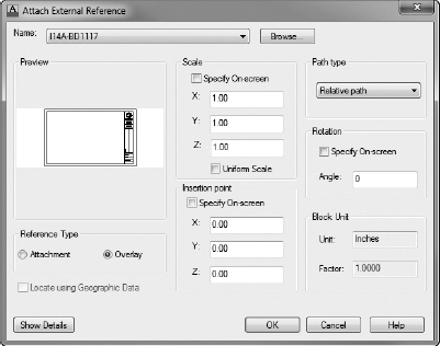
The Attach External Reference dialog box opens; here you will configure how your title block is referenced.
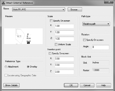
- Using Figure 14.16 as a guide, set the parameters within the Attach External Reference dialog box as follows:
- Reference Type: Overlay
- Scale
Specify On-Screen: Unchecked
X, Y, and Z: 1
- Insertion Point
Specify On-Screen: Unchecked
X, Y, and Z: 0
- Path Type: Relative Path
- Rotation
Specify On-Screen: Unchecked
Angle: 0
FIGURE 14.16 Attaching the title block as an external reference
- With these settings in place, click OK.
The title block is referenced in the DWFX-1117 (DWFX-A3) layout tab.
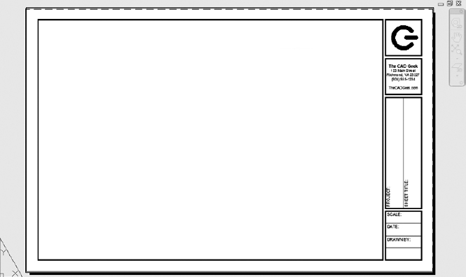
- Save the current drawing template, keeping its I14A-BDTPLT.dwt (M14A-BDTPLT.dwt) filename. Your sheet template should look like Figure 14.17.
With the title block inserted into your sheet template, all that's left to do is insert the sheet information block. As you may recall, this block was created with several fields embedded as the default value for the block attributes. Many of these tie into Sheet Set Manager, a feature you'll learn about later in this chapter, but the Drawn By attribute pulls its value from the drawing file properties. In addition to inserting the sheet information block, you'll also learn how to set this attribute by changing the drawing file properties.
- Continue using I14A-BDTPLT.dwt (M14A-BDTPLT.dwt), or open it if it's not already open.
- Create a layer named A-ANNO-TTLB-TEXT with a color of 5, and set the layer as current.
FIGURE 14.17 The sheet template with the title block referenced into it
- Click the Insert button within the Block panel on the Insert tab to open the Insert dialog box.
- Click the Browse button in the Insert dialog box, and browse to the I-TTLB-INFO.dwg (M-TTLB-INFO.dwg) file that you created earlier in this chapter.
Because the I-TTBL-INFO (M-TTBL-INFO) block, like the title block reference, was created with a common insertion point, you use the default Insertion Point of 0,0,0, Scale of 1, and Rotation of 0.
- Make sure your Insert dialog box looks like Figure 14.18, and then click OK.
Because the I-TTLB-INFO (M-TTLB-INFO) block contains block attributes, the Edit Attributes dialog box opens upon inserting the block into your drawing.
- You'll use Sheet Set Manager to populate these attributes, so click OK to accept their default values.
With the exception of the DRAWN_BY and DRAWING_SCALE attributes, the default value for each block attribute contained within the TTLB-INFO block hooks into Sheet Set Manager. Instead of hooking into Sheet Set Manager, the DRAWN_BY attribute pulls its value from the drawing's properties. The DRAWING_SCALE attribute will be set separately as you configure viewports later in this chapter.
FIGURE 14.18 Inserting the I-TTLB-INFO (M-TTLB-INFO) block
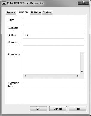
- Open the Properties dialog box by choosing Application menu Drawing Utilities Drawing Properties.
- Switch to the Summary tab in the I14A-BDTPLT.dwt (M14A-BDTPLT.dwt) Properties dialog box.
- From the Summary tab, change the value of the Author field to your initials (see Figure 14.19).
FIGURE 14.19 Changing the Author drawing property
- Click OK to return to the drawing.
The DRAWN_BY attribute probably won't update as soon as you return to the drawing.
- Enter REA at the command line to force a regeneration of the entire drawing.
As shown in Figure 14.20, the DRAWN_BY attribute displays your initials.
FIGURE 14.20 The Author drawing property displaying as a field in the title block
- Save and close the current I14A-BDTPLT.dwt (M14A-BDTPLT.dwt) file, keeping its name.

This concludes the setup of your sheet template drawing. You're now ready to begin creating sheets by using this template. The first sheet you'll create, and perhaps one of the simplest, is a cover sheet.
Creating Your First Plan Sheet
The reason you referenced the title block drawing in your plan sheet template was to keep from having to reference it manually in each and every plan sheet. Once you've referenced it in the plan sheet template drawing, AutoCAD will automatically attach the reference, on the correct layer, to each plan sheet you create. Sheet Set Manager provides a slightly more streamlined sheet creation process, but for those times when you may not want to use Sheet Set Manager, this process is one of the more common approaches. Choosing whether to use Sheet Set Manager isn't something you have to do from the start. You'll add the cover sheet you're about to create as an existing drawing to your sheet set.
- Create a new drawing by using the Application menu or Quick Access toolbar.
- Use the down-arrow next to the Open button in the Select Template dialog box to choose Open With No Template - Imperial (Open With No Template - Metric).
- Right-click the Quick View Layouts button in the status bar, and choose From Template (see Figure 14.21).
FIGURE 14.21 Selecting the From Template option in the Quick View Layouts context menu
- Browse to the I14A-BDTPLT.dwt (M14A-BDTPLT.dwt) file you created in the preceding section, and click Open from the Select Template From File dialog box.
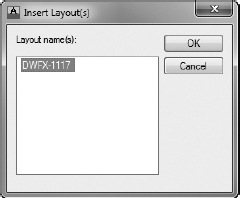
- The Insert Layout(s) dialog box opens, and it lists each of the layout tabs in the selected template drawing. Choose the DWFX-1117 (DWFX-A3) option shown in Figure 14.22, and then click OK.
FIGURE 14.22 Selecting the layout to use as a template
A new layout tab named DWFX-1117 (DWFX-A3) is created in the current drawing. This tab is an exact copy of the DWFX-1117 (DWFX-A3) layout tab in the I14A-BDTPLT.dwt (M14A-BDTPLT.dwt) file.
Similar to the layer- and file-naming standards, the National CAD Standard also outlines the numbering of drawing sheets. The standard sheet number for an architectural cover sheet is A-000.
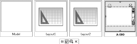
- Click the Quick View Layouts button in the status bar to display thumbnails of the layout tabs in your drawing (see Figure 14.23).
FIGURE 14.23 Renaming a layout tab to match the sheet number
- Right-click the DWFX-1117 (DWFX-A3) layout tab, and choose Rename from the contextual menu that displays.
- Enter A-000 as the new name for the layout tab, and then press (see Figure 14.23).
Because layout tabs are used in many ways, it's important to establish a naming convention for them. One of the most popular conventions is to name the layout tab after the sheet number it represents.
You will need only a single layout tab for the cover sheet drawing. Too many layout tabs in a drawing can dramatically affect drawing performance, so you should keep the total number as low as possible. For this reason, you'll delete the unneeded Layout1 and Layout2.
- Click the Quick View Layouts button on the status bar to display thumbnails of the layouts in your drawing.
- Right-click Layout1, and choose Delete from the contextual menu that appears. Do the same for Layout2.
When finished, clicking the Quick View Layouts button will display only two thumbnails: one for Model and another for the A-000 layout.
- Save your cover sheet as I-A-000.dwg (M-A-000.dwg) in the Sheets directory you created earlier.

Using Sheet Set Manager
To many, Sheet Set Manager is nothing more than a glorified PLOT command. Although it can certainly be used that way, Sheet Set Manager is truly designed to help you manage your plan sheets from the moment you create a sheet to the moment you plot it. This section focuses on using Sheet Set Manager to create and manage your plan sheets. To begin using Sheet Set Manager, you must first create a sheet set.
Creating a New Sheet Set
By using Sheet Set Manager, you can organize each of your drawing sheets (layouts) into what is known as a sheet set. A sheet set will store links to each of your drawings, in addition to storing basic information about each drawing and how new drawings should be created. All of this information is stored in a sheet set data (DST) file. This data file is created by completing a wizard enabling you to create a sheet set from scratch or from a template.
To create the sheet set data file for your cabin project, take the following steps:
 With any drawing open, select the Sheet Set Manager tool found on sheets the Palettes panel of the View tab.
This opens the Sheet Set Manager palette set.
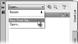
- With the Sheet Set Manager palette set open, select the drop-down list on the Sheet List palette and select New Sheet Set, as shown in Figure 14.24.
FIGURE 14.24 Creating a sheet set by using the Sheet List palette
The Sheet Set Manager palette set is typically referred to as Sheet Set Manager. Sometimes you may see Sheet Set Manager abbreviated as SSM.
The Create Sheet Set dialog box opens. This dialog box is divided into four segments (pages):
- From the Begin step, select An Example Sheet Set and then click Next.
This takes you to the second step, Sheet Set Example. Like drawing templates, sheet set templates can be created as well. If you were creating a sheet set from a template, this dialog box is where you would specify that example sheet set.
- You will build your sheet set from scratch, so select the A Sheet Set To Use As An Example radio button, and then pick Architectural Imperial Sheet Set (Architectural Metric Sheet Set) from the list below.
- Click Next to advance to the next step.
Now you'll need to provide a name for your sheet set. Although this name won't be set up to print on any drawings, it's still important to enter a meaningful name that will make sense to you later. In addition to choosing a name for your sheet set, you will also tell AutoCAD where to save your sheet set.
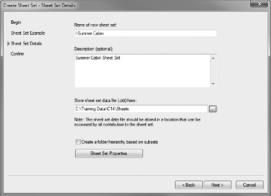
- In the Name Of New Sheet Set text box, enter I-Summer Cabin (M-Summer Cabin).
You may enter an optional description in the Description text box.
- Finally, and perhaps most important, click the ellipsis button at the end of the Store Sheet Set Data File (.dst) Here text box to choose the Sheets directory you created earlier in this chapter.
When you're finished, the Create Sheet Set - Sheet Set Details dialog box should look like Figure 14.25.
- At the bottom of the Create Sheet Set - Sheet Set Details dialog box, pick the Sheet Set Properties button to open the Sheet Set Properties - Summer Cabin dialog box.
Because you selected one of the generic sheet set templates that ship with the product, many of the Sheet Set Properties are set to generic values. You'll change some of these properties to work with your project and, more specifically, the sheet template you created earlier. Look ahead to Figure 14.27 to see the Sheet Set Properties dialog box configured for the Summer Cabin project.
- Pick the Page Setup Overrides File property under the Sheet Set property group, and then select the ellipsis button.
- From the Select Template dialog box that opens, browse to and select the I14A-BDTPLT.dwt (M14A-BDTPLT.dwt) file and click Open.
FIGURE 14.25 Choosing a name and location for the sheet set
- Verify that the Sheet Storage Location property under the Sheet Creation group is set to the Sheets directory within your Chapter 14 directory.
- Choose the Sheet Creation Template property, also under the Sheet Creation group, to browse to and select the same I14A-BDTPLT.dwt (M14A-BDTPLT.dwt) file selected in step 10.
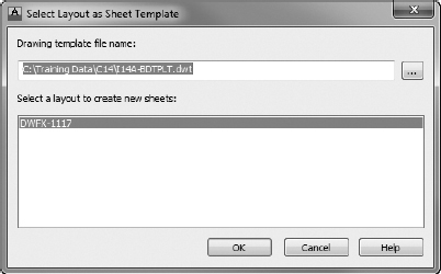
Once you select the template file, the Select Layout As Sheet Template dialog box shown in Figure 14.26 opens.
FIGURE 14.26 Selecting the sheet-creation layout template
- Select the DWFX-1117 (DWFX-A3) layout from the list, and then click the OK button to exit the dialog box.
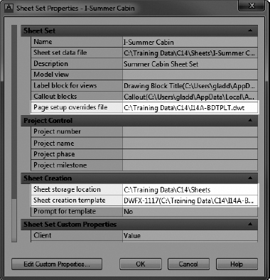
- Verify that the Sheet Set Properties - Summer Cabin dialog box looks like Figure 14.27, and then click the OK button to save the settings and exit the dialog box.
FIGURE 14.27 The Sheet Set Properties dialog box configured for the Summer Cabin project
- Back in the Create Sheet Set dialog box, click the Next button to advance to the Confirm portion of the wizard.
- Click Finish to create the sheet set, and exit the wizard.
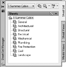
After the Sheet Set Wizard closes, the Sheet List palette within the Sheet Set Manager palette set will display a number of groups. These were created based on the architectural sheet set template you selected while creating the sheet set (see Figure 14.28).
Throughout the life cycle of a project, you may need to make changes that affect the entire sheet set. Sheet Set Manager consists of two parts: the sheet and the sheet set. The difference is that sheet set properties affect the entire drawing set (every drawing listed in the Sheet Set Manager sheet list), and sheet properties affect only that one individual sheet. The difference between the two will become more apparent the more you work with Sheet Set Manager.
You may recall that the sheet set name does not get plotted on a drawing sheet. Instead, Sheet Set Manager will use a different Project Name property on the individual drawings. This property is a sheet set property, which means that it affects the entire drawing set and will be the same for every drawing in the entire set.
FIGURE 14.28 The Summer Cabin sheet set
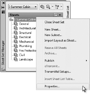
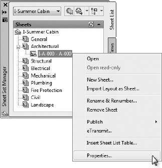
- From the Sheet List palette in Sheet Set Manager, right-click Summer Cabin at the top of the sheet list and select Properties, as shown in Figure 14.29.
FIGURE 14.29 Modifying the properties for the sheet set
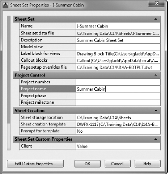
The Sheet Set Properties - Summer Cabin dialog box opens to display properties common to the entire sheet set. Notice that the Project Name property under the Project Control group is currently empty.
- Click the Project Name property to make it active, and enter Summer Cabin as the project name, as shown in Figure 14.30.
- This is the only change you will make for now, so click OK when you're finished.
FIGURE 14.30 Changing the Sheet Set Manager Project Name property
You have now created a sheet set for your cabin project. Currently, the sheet set includes only the collection of settings that tell AutoCAD how you would like to create sheets and where those sheets should be stored. The next several exercises will show you not only how to create new sheets by using Sheet Set Manager but also how to add existing sheets to a sheet set.
Adding Existing Drawings to a Sheet Set
In the “Creating Your First Plan Sheet” exercise, you created a cover sheet drawing by using the drawing template created in the “Setting Up a Sheet Template” section. Although the drawing was saved alongside the sheet set in the Sheets directory, the A-000.dwg file is not yet part of the Summer Cabin sheet set. Because this drawing was created outside Sheet Set Manager, you'll need to add it manually.
Take these steps to add the cover sheet to your Summer Cabin sheet set:
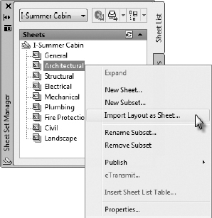
- Right-click the Architectural group on the Sheet List panel of Sheet Set Manager, and choose Import Layout As Sheet (see Figure 14.31).
FIGURE 14.31 Importing an existing layout into Sheet Set Manager
The Import Layouts As Sheets dialog box opens.
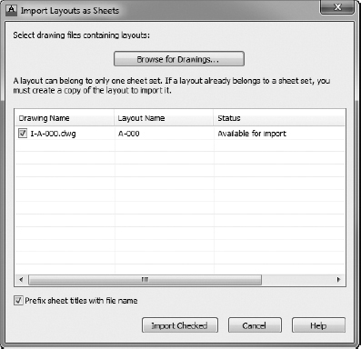
- From the Import Layouts As Sheets dialog box, click the Browse For Drawings button at the top of the screen. Browse to and select the I-A-000.dwg (M-A-000.dwg) file saved in your Sheets directory.
After you select the I-A-000.dwg (M-A-000.dwg) drawing, the layouts contained within it are listed in the Import Layouts As Sheets dialog box (see Figure 14.32). Because the drawing you selected had only one layout, the A-000 layout is the only one listed.
When you're importing existing layouts, it's important to note the Status column. The status for the A-000 layout should read Available For Import, and the check box should be selected on the left side of the dialog box.
- Click the Import Checked button to import the layout and return to the Sheet Set Manager palette set.
The A-000 layout tab imports into the Sheet Set Manager sheet list with the generic name I-A-000 - A-000 (M-A-000 - A-000), as shown on the left in Figure 14.33. For the layout to be useful in Sheet Set Manager, you'll need to provide a more meaningful sheet number and title.
FIGURE 14.32 Importing the A-000 layout tab into Sheet Set Manager
FIGURE 14.33 Accessing the properties for an individual sheet to replace its default name in Sheet Set Manager
- From the Sheet List palette in Sheet Set Manager, right-click the I-A-000 - A-000 (M-A-000 - A-000) sheet and choose Properties, as shown on the right in Figure 14.33.
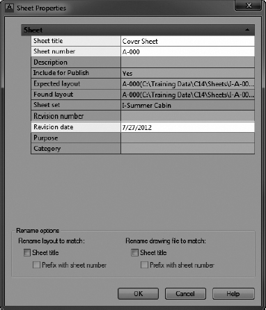
The Sheet Properties dialog box opens to display settings related to the A-000 sheet.
- Enter the following values, as shown in Figure 14.34:
Sheet Title: Cover Sheet
Sheet Number: A-000
Revision Date: Today's date
FIGURE 14.34 Changing the properties for sheet A-000
- Click OK to return to Sheet Set Manager.
- Double-click A-000 - Cover Sheet from the Sheet Set Manager sheet list to open it.
You may need to enter REA
to regenerate the drawing, but notice how the title block is largely completed, as shown in Figure 14.35. All of this information is pulled from the properties you set in Sheet Set Manager.Notice that the Drawn By box is empty. Remember, this is not a Sheet Set Manager field; it comes from the DWG file properties.
FIGURE 14.35 The sheet information block populated with values from Sheet Set Manager
- Choose Application menu Drawing Utilities Drawing Properties, and then change the Author property on the Summary tab to your initials and click OK.
The Properties dialog box closes, and you return to the drawing. Once again, you may need to enter REA
to regenerate your drawing, but afterward the sheet information block will reflect this change to the drawing properties. - Save and close the current file, I-A-000.dwg (M-A-000.dwg), keeping its name.

Importing existing layouts into Sheet Set Manager is a great way to build a sheet set out of existing drawings. However, it's also common to use this process when creating new drawings. The next section focuses on the creation of new plan sheets. Later in this chapter, you'll add viewports to the sheets created in the next section. Those sheets will then be copied, creating additional layouts in each of the newly created drawings. You'll then apply the process you learned in this section to import those additional layouts into your sheet set.
Creating Drawings with Sheet Set Manager
Rather than importing existing sheets, you can also create new sheets by using Sheet Set Manager. You may recall setting the Sheet Storage Location and Sheet Creation Template properties as you were creating the sheet set for your Summer Cabin project. These settings will be used to determine the template from which your sheets will be created. Consequently, when creating sheets, Sheet Set Manager will prompt you for only three items: sheet number, sheet name, and drawing filename.
Having too many layouts in a single drawing can affect drawing performance, so you should keep the total number in a drawing to a minimum. Sheet Set Manager creates drawings with only a single layout. After configuring your viewports, you'll learn how to copy layouts, later in this chapter. Copied layouts can be added to your sheet set by using the same Import Layout As Sheet command used to add the cover sheet to the sheet set.
For now, you'll use Sheet Set Manager to create three drawing files. Each will represent a different portion of your overall sheet set. Specifically, you'll create a drawing for sheets illustrating your floor plan, another for elevations, and yet another for the site plan. You'll copy the initial layout contained in each drawing created in this section later in this chapter. After copying these layouts, you'll import them into your sheet set.
Follow these steps to create drawings for each of the three drawing groups:
- With any drawing open, right-click Summer Cabin at the top of the Sheet List palette of Sheet Set Manager and select New Sheet, as shown in Figure 14.36.
FIGURE 14.36 Creating a new sheet by using Sheet Set Manager
The New Sheet dialog box shown in Figure 14.37 opens, where you will enter some basic information about the drawing you're about to create. This information will include the sheet number, sheet title, and drawing filename.
FIGURE 14.37 Entering the sheet number, sheet title, and filename in the New Sheet dialog box
NOTE Take note of the Folder Path and Sheet Template settings. Both are grayed out and cannot be changed. Because you set both of these as properties as you created the sheet set, Sheet Set Manager automatically uses the correct template and saves the drawing in the correct location. - Enter A-101 in the Number text box, and enter Floor Plan for the Sheet Title.
By default, the filename is automatically generated by combining what you enter for the Number and Sheet Title.
- To change this, click in the File Name text box and enter I-A-100 (M-A-100).
When you're finished, the New Sheet dialog box should look like Figure 14.37.
- Click OK to create the new drawing.
In this case, the sheet A-101 belongs to a group of drawings, each numbered A-100. Instead of naming the file I-A-101.dwg (M-A-101.dwg), name it I-A-100.dwg (M-A-100.dwg) to represent the group of layouts it will contain accurately.
Take note of where the A-101 sheet is located in the sheet list. Unlike the A-000 drawing you imported earlier, the A-101 sheet doesn't belong to any group. Sheets can be moved and rearranged throughout a sheet set by dragging and dropping them into the desired location. Keep in mind that you're moving only the location where a sheet resides within Sheet Set Manager and that you are not modifying the DWG file or the directory in which it's stored.
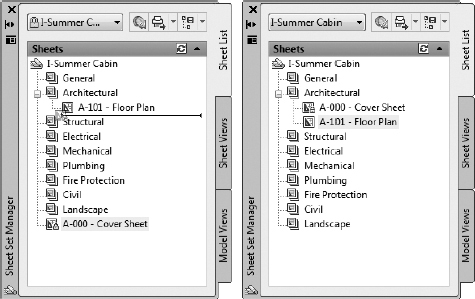
- Drag and drop the A-101 - Floor Plan drawing from the bottom of the Sheet List palette to the Architectural group, under the A-000 Cover Sheet drawing (see the left image of Figure 14.38).
When finished, the A-101 drawing sheet will be listed in the Architectural group after the A-000 drawing sheet (see the right image of Figure 14.38).
FIGURE 14.38 Rearranging a drawing in the Sheet Set Manager sheet list
- Right-click the Architectural group, and select New Sheet.
Notice the layout name and drawing path for the Sheet Template. The Sheet Template path differs from the one you saw in Figure 14.37.
Each group (or subset, as they're known in Sheet Set Manager) can have its own settings. You'll need to configure the Architectural subset to use the sheet template and DWFX-1117 (DWFX-A3) layout.
- Click the Cancel button to exit the New Sheet dialog box.
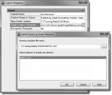
- Right-click the Architectural subset, and choose Properties.
The Subset Properties dialog box opens.
- From the Subset Properties dialog box, click in the Sheet Creation Template property and browse to your I14A-BDTPLT.dwt (M14A-BDTPLT.dwt) file to select the DWFX-1117 (DWFX-A3) layout, as shown in Figure 14.39.
- Return to the Architectural subset, and choose New Sheet by right-clicking the subset name.
The New Sheet dialog box opens once again. This time the Sheet Template path should begin with DWFX-1117 (DWFX-A3) and include the path to your Training Data folder in parentheses.
FIGURE 14.39 Selecting the DWFX-1117 (DWFX-A3) layout as the Sheet Creation template for the Architectural subset
- In the New Sheet dialog box, enter the following values:
Number: A-201
Sheet Title: North Elevation
File Name: I-A-200 (M-A-200)
- Click OK to create the drawing.
- Change the Sheet Creation Template for the Civil subset to match the Architectural subset, and create a new sheet with the following designations:
Number: C-100
Title: Site Plan
Filename: I-C-100 (M-C-100)


You should now have a total of four sheets listed in the Sheet Set Manager sheet list—three under the Architectural subset and one under the Civil subset (see Figure 14.40).
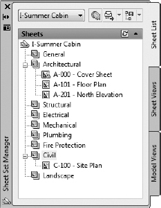
FIGURE 14.40 The Sheet List palette after importing the cover sheet and creating three new sheets
Setting Up Layouts
The preceding section guided you through the process of setting up a series of blank drawings and adding each of them to Sheet Set Manager. For now, most of your work with Sheet Set Manager is done. This section focuses on adding content to each of the layouts or plan sheets you have created so far. You'll add content to your plan sheets by cutting a viewport.
Viewports create a hole or window in the layout so that you can see through the layout to the drawing of the building. You can think of the building as residing “underneath” the layout. You'll create these viewports to display your cabin in model space at a precise scale. When you're finished, everything within the dashed border will be printed as if it were a single drawing.
Referencing the Model
Chapter 13 introduced external references (xrefs), which are useful and powerful tools for viewing a second drawing from within the current drawing. In this section, you'll learn to use xrefs to assemble plan sheets, which will allow you to get even more mileage out of them. Xrefs help you combine several drawings into a composite; layouts allow you to set up and print several views of the same file. The layout is a view of your drawing as it will sit on a sheet of paper when printed.
The first step to creating viewports is to make sure that there's something in model space to see. You'll do that by referencing the floor plan and site plan layout drawings in your sheet files as necessary. This practice is rather common in the building industry, as a typical building project will include a large number of model files representing the many building trades and designs within those trades.
For example, the mechanical engineer will likely create several model files, including a duct layout plan, a piping plan if natural gas or chilled water is being used, and an equipment plan. Each of those plans will use the architectural floor plan as a background to the mechanical design, but certain architectural elements, such as the furniture plan, have little relevance to the mechanical engineer. Therefore, to help facilitate the multidisciplinary collaboration required by today's projects, the architect will, like the other disciplines on the project, divide the design across multiple model files.
Although your cabin project consists of only a couple of model files, you'll set up your drawings to use this same collaborative framework by using external references to manage which parts of the project display on a given plan sheet. With the exception of the cover sheet, each of the sheets in your sheet set will reference the I14A-FPLAYO.dwg (M14A-FPLAYO.dwg) file. In addition to this file, the civil site plan will also reference I13C-SPLAYO.dwg (M13C-SPLAYO.dwg).
Take the following steps to reference the necessary model files into your sheet files:
- Open the I-A-100.dwg (M-A-100.dwg) sheet file by double-clicking the A-101 sheet in Sheet Set Manager.
- With the I-A-100.dwg (M-A-100.dwg) sheet file open, use the Quick View Layouts button to switch to model space.
- Set the current layer to A-ANNO-REFR.
- Use the XREF command to attach I14A-FPLAYO.dwg (M14A-FPLAYO.dwg) to the current drawing.
- Configure the Attach External Reference dialog box to match Figure 14.41.
- Save the current drawing, keeping its existing filename.
FIGURE 14.41 The Attach External Reference dialog box
- Repeat steps 2 through 6 on the I-A-200.dwg (M-A-200.dwg) and I-C-100.dwg (M-C-100.dwg) drawings.
The Site Plan sheet is the only one that requires two xrefs to compose the entire drawing.
- Open the I-C-100.dwg (M-C-100.dwg) file, if it's not already open.
- Verify that A-ANNO-REFR is the current layer and that I14A-FPLAYO.dwg (M14A-FPLAYO.dwg) is already attached as an xref.
- Matching the settings shown in Figure 14.42, attach I13C-SPLAYO.dwg (M13C-SPLAYO.dwg).
- When prompted to specify an insertion point, use the Endpoint osnap to select the upper-left corner of the deck, as shown in Figure 14.43.
- Keeping their existing filenames, save and close any of the sheet drawings still open: I-A-100.dwg, I-A-200.dwg, and I-C-100.dwg (M-A-100.dwg, M-A-200.dwg, M-C-100.dwg).
You have now attached the necessary external references for each of your plan sheets. Although these references are attached, the actual layouts still contain nothing more than the title block you inserted earlier in this chapter. The next step to constructing your plan sheets will be to cut a hole into your layouts by using viewports. These viewports will allow you to look into model space at an exact scale.
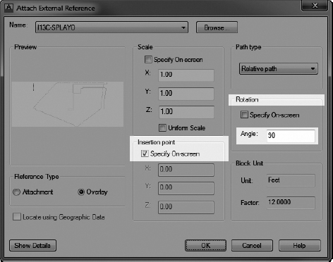
FIGURE 14.42 Attaching the civil site plan drawing
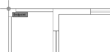
FIGURE 14.43 Choosing the insertion point for the civil site plan xref
Creating the Paper Space Viewport
Now that the sheet files have been created and the necessary model files referenced, you need to be able to view the model hidden behind the layouts. You will do this by creating a new viewport that won't show up when you plot the drawing. Here's how:
- Open I-A-100.dwg (M-A-100.dwg), and then use the Layer drop-down list on the Layers panel of the Home tab to change the current layer to A-ANNO-NPLT.
You'll create your viewports on this layer so that the borders for your viewports are not plotted in your final plan sheets.
TIP Note the color assigned to the A-ANNO-NPLT layer. Because this layer will be used for viewports, it's useful to assign the layer a color that will stand out in your drawing so that you can quickly identify its boundaries as viewport boundaries and not another AutoCAD object such as a polyline.Part of this section focuses on configuring the visibility of layers inside your viewports. When you're creating viewports, it's best to make the objects you'll be displaying in a plan sheet visible from the start.
 Expand the Layers panel on the Home tab, and then click the Turn All Layers On button to turn on all layers in the current drawing and the drawings referenced in it.
 Repeat the same process, but this time choose the Thaw All Layers button to thaw all of the layers.
 Click the Layout tab and then, in the Layout Viewports panel, click Rectangular the Rectangular button.
- At the Specify corner of viewport: prompt, click the endpoint at the upper-right corner of the title block.
- At the Specify Opposite Corner: prompt, click the endpoint at the lower-left corner of the title block.
Your cabin drawing appears in the new viewport (see Figure 14.44).
- Open the I-A-200.dwg (M-A-200.dwg) sheet file, and repeat steps 2 to 6, making sure A-ANNO-NPLT is the current layer before creating your viewport.
The relationship between paper space and model space is quite interesting. Viewports allow you to peer into model space from your layouts. The end result is a drawing sheet that, when plotted, displays everything drawn in paper space in addition to model space objects drawn inside the viewport boundary. To help you experience how this relationship works, try the following:
- Place your cursor over an object inside the cabin, click just once, and then move the cursor.
Rather than selecting the object, you began a selection window.
- Drag the window around some of the objects near the cabin, and then click again. Nothing is selected.
FIGURE 14.44 The cabin displayed through the new viewport
- Move the cursor over both the white and gray areas of the drawing window, and notice how the crosshairs appear over both.
This informs you that you are currently working in paper space and can select only paper space objects such as the viewport (after you move the objects into paper space in the next section), the title block, and border. To work on the cabin itself, you need to change to model space. You can do this in two ways:
- Click the Model button. This temporarily removes the layout and leaves you with just the drawing, or model.
- Switch to model space while a layout is active.
You'll use the latter here.
When you activate model space while a layout is active, it is like opening a window and reaching through the opening to touch the drawing of the building behind the window.
- Place your cursor within the viewport area, and double-click this time.
The viewport border becomes bolder and, when you move the cursor beyond the viewport, the cursor changes from a crosshair to an arrow. You are now in model space and are able to select the model space objects but not any objects that reside in paper space.
- Double-click the cursor outside the viewport.
The crosshair cursor returns, and you are back in paper space.
![]() TIP You can also click the Model button in the middle of the status bar to move from model space to paper space. When you are in paper space, this button changes to Paper, and it will toggle you back to the current model space viewport.
TIP You can also click the Model button in the middle of the status bar to move from model space to paper space. When you are in paper space, this button changes to Paper, and it will toggle you back to the current model space viewport.
Setting the Viewport Scale
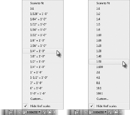
The layout is set to print to an 11″×17″ (297 mm×420 mm) paper, and you want the contents of the viewport to plot to a specific scale. In this section, you will adjust the viewport scale to display the model space objects at ![]() (1 = 50) by assigning a viewport scale.
(1 = 50) by assigning a viewport scale.
 Select the viewport.
You know that the viewport is selected, and not the border polyline, when the Viewport Scale button appears in the status bar.
TIP Because the viewport and the title block are drawn atop one another, try using Selection Cycling if you're having a hard time selecting the viewport.- Click the Viewport Scale button and, from the drop-down list, choose
 , as shown in Figure 14.45.
FIGURE 14.45 Selecting the imperial viewport scale (left) and the metric viewport scale (right)
The viewport scales to
, and the scale is reflected on the status bar.You can also change the viewport scale by selecting the viewport and changing the Standard Scale value in the Properties palette or Quick Properties panel.
- Double-click in the viewport if necessary to switch to model space, and then use the Pan tool inside the viewport to adjust the position of the cabin so that the floor plan is centered (see Figure 14.46).
FIGURE 14.46 The cabin drawing zoomed in to the floor plan
The scene is a bit cluttered, but that will be rectified in a later section.
TIP It's recommended you use the actual PAN command instead of the middle mouse button. Because Zoom and Pan are shared by the middle button/wheel on mice, it's easy to change the drawing scale accidentally by zooming. Using the PAN command will avoid this possibility. - Double-click the gray area outside the title block to switch back to paper space.
- Keeping its current name, save I-A-100.dwg (M-A-100.dwg) and open I-A-200.dwg (M-A-200.dwg).
TIP Items such as tables and notes can go either in model space, as shown in this exercise, or in paper space. When they are in paper space, it's easy to develop and maintain a consistent text or table style that appears the same in all drawings. When notes and tables are in model space, you have the flexibility to change their sizes simply by zooming in or out in the viewport. Model space objects can also be shown in any number of layouts in the same drawing. You'll develop your own standard, or adhere to your company's standard, for note and table placement.
- Repeat steps 1 to 4 on the I-A-200.dwg (M-A-200.dwg) file. Instead of using the PAN command to bring the floor plan into view, bring the north elevation into view.
The north elevation currently faces opposite the World UCS. You'll fix the elevation's view in a later exercise.
Copying the Layouts
The layout that you made is an excellent starting point. You will add a few items from the Autodesk® Content Explorer™, adjust the title block information, and then duplicate the layouts several times to accommodate the different views of your cabin. Each time a layout is copied, all of its contents, including the viewports and their settings, are copied with it. These copies are not interdependent, and any changes made to one are not reflected in the others.
You can delete all the paper space layouts, but you can't delete model space.
Adding Content from the Autodesk Content Explorer
Before you copy the layouts, you'll add a block by using the Autodesk Content Explorer and then edit its attributes. The Autodesk Content Explorer is similar to DesignCenter in the way that it provides access to blocks, layers, linetypes, styles, and modes. Unlike DesignCenter, Content Explorer is built from an index of user-specified locations spanning from your local hard drive to network paths. The end result is a Google-like index that allows you to access drawing files (and their contents) quickly with a simple search query.
To see how this feature works, you'll use the Autodesk Content Explorer to locate a view title block:
- Use Sheet Set Manager to open the A-101 layout in the I-A-100.dwg (M-A-100.dwg) file.
- Use the Layers drop-down list on the Home tab to make A-ANNO-TTLB-TEXT current.
- Open the Autodesk Content Explorer on the Plug-Ins tab Content panel Explore button.
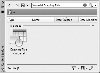
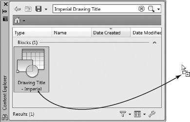
- In the Search field atop the Content Explorer palette, enter the search query Imperial Drawing Title (Metric Drawing Title).
After executing the search query, the Content Explorer returns content from its indexed (Watched Folder) locations (see Figure 14.47).
FIGURE 14.47 The Autodesk Content Explorer returning search results
ADDING WATCHED FOLDERS TO CONTENT EXPLORER
The Autodesk Content Explorer will search only indexed content sources. You may add any directory on your local computer to this index by clicking the Add Watched Folder button at the bottom of the Content Explorer palette. Installing the Autodesk Content Service on a file server will allow network directories to be added to the Content Explorer index. To install the Autodesk Content Service on a network server, run the AutoCAD 2013 installer on your server and choose Install Tools & Utilities.
- Locate the Drawing Title - Imperial (Drawing Title - Metric) block within the search results, and insert it into your drawing by dragging it from the Content Explorer palette into the drawing area (see Figure 14.48).
- Make the Drawing Name the same as the Sheet Name in Sheet Set Manager by completing the following:
- Select the VIEWNAME tag in the Enhanced Attribute Editor.
- Right-click in the Value field, and select Insert Field.
- Change the Field Category to SheetSet, and then select the CurrentSheetTitle Field Name from the Field dialog box.
- Click OK.
FIGURE 14.48 Inserting a block from the Autodesk Content Explorer
Using Fields to Acquire a Viewport Scale Automatically
Instead of manually entering a viewport scale, you'll use a field to acquire the scale dynamically:
- Erase the contents of the Viewport Scale attribute value.
- Right-click, and select Insert Field.
- From the Field dialog box that opens, select Objects for Field Category and Object from the Field Names list box.
Because the list of AutoCAD objects is quite lengthy, you must first select an object to acquire the properties of an object within a field.
- Click the Select Objects button, and then select the viewport on sheet A-101.
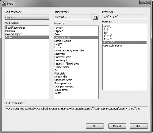
The Field dialog box updates to display a complete list of available viewport properties (see Figure 14.49).
FIGURE 14.49 Acquiring the viewport scale by using fields
- With the viewport properties displayed within the Field dialog box, choose Custom Scale for Property and #″ = 1′-0″ (1:#) for Format.
When you are finished, the Field dialog box should look like Figure 14.49.
- Click OK to return to the Enhanced Attribute Editor dialog box.
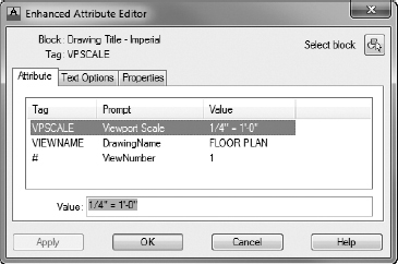
The Viewport Scale attribute is now populated using a field, as shown in Figure 14.50.
FIGURE 14.50 The completed Enhanced Attribute Editor dialog box
- Click OK to accept the block attribute values.
- Place the Drawing Title - Imperial (Drawing Title - Metric) block within the layout tab for sheet A-101, and save the I-A-100.dwg (M-A-100.dwg) drawing, keeping the current name.
- Use the procedure outlined in steps 1–7 to acquire the viewport scale automatically for the SCALE attribute value within the drawing sheet title block.
- Edit the SCALE attribute by double-clicking the placeholder value.
The new block assigns the necessary context to the Floor Plan view. In addition to the title itself, the block provides a unique view number and drawing scale, two components that are especially helpful as you begin coordinating with contractors and other consultants.
After inserting this block, the static FLOOR PLAN text saved in I14A-FPLAYO.dwg (M14A-FPLAYO.dwg) is no longer needed. You'll use the Edit Reference In-Place tool to erase this text from the floor plan xref:
- Make sure that I-A-100.dwg (M-A-100.dwg) is open, and switch to model space by using the Quick View Layouts button in the status bar.
- Zoom in to the FLOOR PLAN text, and then select the I14A-FPLAYO.dwg (M14A-FPLAYO.dwg) xref.
The contextual External Reference Ribbon tab opens to display common commands related to xrefs.
 Select the Edit Reference In-Place tool from the Edit panel on the contextual External Reference tab.
Alternatively, you can double-click the xref or enter REFEDIT
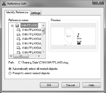
at the command line to start this command.- From the Reference Edit dialog box that opens (shown in Figure 14.51), select the I14A-FPLAYO (M14A-FPLAYO) reference and click OK.
The contextual Edit Reference panel is appended to each Ribbon tab.
- Erase the FLOOR PLAN text.
- With the floor plan reference open in the Reference Editor, adjust your dimensions as needed so that they will fit on your drawing sheet without conflict.
- After completing these steps, pick the Save Changes (REFCLOSE) button on the contextual Edit References panel.
FIGURE 14.51 Opening the I14A-FPLAYO.dwg (M14A-FPLAYO.dwg) reference from the Reference Edit dialog box
- Choose OK from the AutoCAD dialog box alerting you that “All reference edits will be saved.”
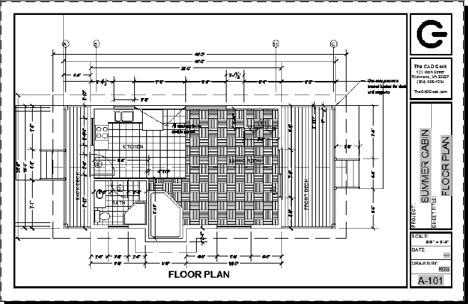
- Switch back to the A-101 layout tab, and adjust the location of the Drawing Title block if necessary.
Your A-101 layout should look like Figure 14.52.
FIGURE 14.52 Floor Plan drawing sheet with Drawing Title block
- Save I-A-100.dwg (M-A-100.dwg) after making these changes.
- Select the Drawing Title - Imperial (Drawing Title - Metric) block, and right-click to choose the Clipboard Copy option from the contextual menu that opens.
- Open the I-A-200.dwg (M-A-200.dwg) file, and switch to the A-201 layout if it's not already current.
- Right-click anywhere in the drawing area, and choose Clipboard Paste To Original Coordinates.
Take note of where the Drawing Title block inserts into the layout tab; its location is exactly the same as the A-101 layout tab. Likewise, the title within the Drawing Title - Imperial (Drawing Title - Metric) block automatically updates to reflect the sheet title from Sheet Set Manager.
- Double-click the Viewport Scale field within the Drawing Title - Imperial (Drawing Title - Metric) block, and associate it with the viewport for the A-201 sheet.
Refer to the exercise in the section “Using Fields to Acquire a Viewport Scale Automatically” earlier in this chapter for a reminder of the steps required to complete this function.
- Repeat step 14, and update the SCALE attribute within the drawing sheet title block, along the right edge of the layout tab.
- Save the current I-A-200.dwg (M-A-200.dwg) drawing, keeping its original name.
Creating Additional Layouts
Your finished document set will include a Floor Plan Materials And Floor Plan Doors plan. The A-101 layout now contains a scaled view of your floor plan. Rather than duplicating all of this work, you'll use the completed A-101 layout as a template for these additional drawings by copying it. Here's how:
- Open I-A-100.dwg (M-A-100.dwg) by double-clicking the A-101 - Floor Plan sheet from the Sheet List palette in Sheet Set Manager.
The I-A-100.dwg (M-A-100.dwg) files open, and you are taken to the A-101 layout.
- Right-click the Quick View Layouts button on the status bar, and select Move Or Copy from the contextual menu that opens.
The Move Or Copy dialog box opens.
TIP Notice the small padlock that displays next to the A-101 sheet in Sheet Set Manager after you open it. This padlock indicates that the drawing is locked, which most likely means that someone else has it open. Hover the cursor over the A-101 sheet to display information about the sheet, including who currently has the drawing open. This is especially helpful when multiple people are working on a project at the same time. - Select the (Move To End) option in the Before Layout portion of the dialog box, and then check the Create A Copy check box (see Figure 14.53).
FIGURE 14.53 Copying a layout by using the Move Or Copy dialog box
- Click OK to copy the layout and exit the Move Or Copy dialog box.
- Click the Quick View Layouts button in the status bar to display thumbnails of the layouts in your drawing.
A second A-101 (2) layout is now listed as one of the layouts.
- Right-click the A-101 (2) layout thumbnail, and choose Rename.
- Rename the layout to A-102 and then press (see Figure 14.54).
FIGURE 14.54 Renaming the copied A-101 layout
- Repeat steps 3 through 7 to create another layout named A-103.
- Save the current I-A-100.dwg (M-A-100.dwg), keeping its existing filename, and then double-click the A-201 sheet from the Sheet Set Manager Sheet List palette to open the I-A-200.dwg (M-A-200.dwg) file.
- If you do not already have two tabs (Model and A-201) just under the drawing area shown in Figure 14.55, start the OPTIONS command and go to the Display tab of the Options dialog box.
FIGURE 14.55 The Layout and Model tabs displayed in the Application window
- From the Display tab, check the Display Layout And Model Tabs check box found in the Layout Elements group in the lower-left portion of the dialog box.
- Click OK to exit the Options dialog box and display the layout and Model tabs in the Application window (see Figure 14.55).
- Press and hold the left mouse button, and then press the Ctrl key on your keyboard.
- Move the mouse to the right and, when a small arrow displays to the right of the A-201 layout tab, release (see the left image of Figure 14.56).
FIGURE 14.56 Using Ctrl+left-click to copy an existing layout (left) and the copied layout (right)
TIP If the layout copies to the left of the A-201 layout, use the mouse to drag the A-201 (2) layout to the end, as shown in the right image of Figure 14.56. - Repeat steps 13 and 14 until you have a total of four layout tabs.
- Select and then right-click the A-201 (2) layout tab, and select Rename from the contextual menu that opens.
- Rename the tab to A-202.
- Repeat this procedure for the other two tabs, renaming them to A-203 and A-204, respectively.
When finished, the Model and layout tabs should look like Figure 14.57.
FIGURE 14.57 Four layout tabs sequentially numbered for each of the elevation drawings
- Save the current I-A-200.dwg (M-A-200.dwg) file (keeping its existing filename).

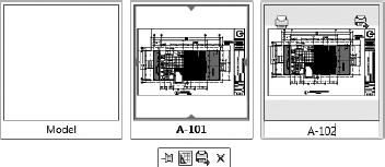
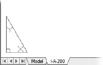
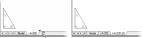
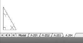
![]() TIP To navigate quickly between layout tabs, press Ctrl + Page Up or Ctrl + Page Down. Page Up will cycle to the left, and Page Down will cycle to the right. This also works with worksheets in Microsoft Excel.
TIP To navigate quickly between layout tabs, press Ctrl + Page Up or Ctrl + Page Down. Page Up will cycle to the left, and Page Down will cycle to the right. This also works with worksheets in Microsoft Excel.
You have now created all of the layouts necessary to document your cabin in a construction document set. Although these layouts are saved in the I-A-100.dwg (M-A-100.dwg) and I-A-200.dwg (M-A-200.dwg) drawings, these new layouts are not yet part of your AutoCAD sheet set. Now you need to add these new layouts to the Summer Cabin sheet set.
Adding New Layouts to Sheet Set Manager
Refer to the “Adding Existing Drawings to a Sheet Set” section if you need to refresh your memory on how to do this. These steps summarize the procedure:
- Right-click the Architectural subset, and choose Import Layout As Sheets.
- Browse to and select the I-A-100.dwg (M-A-100.dwg) and I-A-200.dwg (M-A-200.dwg) files.
- Verify that the layouts you added to the I-A-100.dwg (M-A-100.dwg) and I-A-200.dwg (M-A-200.dwg) files are checked (see Figure 14.58).
FIGURE 14.58 Importing the new layout tabs into the Summer Cabin sheet set
- Click the Import Checked button.
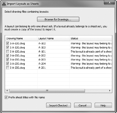
The A-101 and A-201 layouts should have the status “This layout is already part of a sheet set - not available for import.” Because one layout in each drawing is already part of the sheet set, the four new layouts display the status “Warning: this layout may belong to another sheet set.”
Renaming and Renumbering Sheets in Sheet Set Manager
Each of the newly created layouts is now part of the Summer Cabin sheet set. Because these layouts were not created using Sheet Set Manager but rather by copying existing layouts, their name follows a default naming template of drawing name - layout name. This exercise will guide you through renaming and renumbering each of these sheets in an efficient manner:
- With any drawing open, right-click the first sheet representing the newly created layouts in the sheet list, as shown in Figure 14.59, and select Rename & Renumber from the menu that opens.
FIGURE 14.59 Choosing the Rename & Renumber option within the Sheet List panel of Sheet Set Manager
The Rename & Renumber Sheet dialog box shown in Figure 14.60 opens. This dialog box shares many similarities with the New Sheet dialog box but has a number of file management additions. By using the Rename & Renumber Sheet dialog box, you could also rename the layout tabs within each drawing.
The order in which Sheet Set Manager imports the new layouts into your sheet set may vary based on the order they were selected when imported.
FIGURE 14.60 Renaming and renumbering the new layouts
- Enter the corresponding values shown in the following table into the Number and Sheet Title fields in the Rename & Renumber Sheet dialog box.
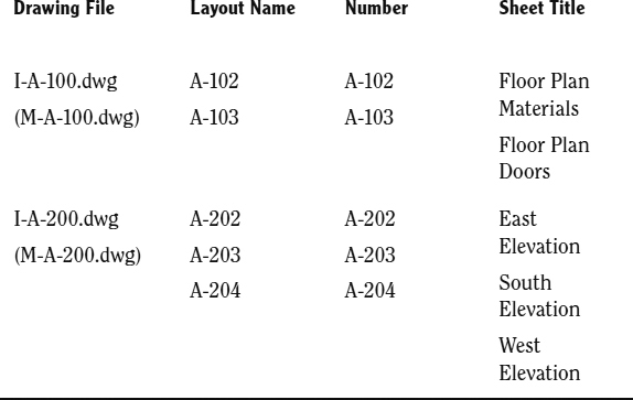
- Using this table as your guide, click the Next button and repeat this process for each sheet.
- After renaming and renumbering each of the newly created layouts, click the OK button to exit the Rename & Renumber Sheets dialog box.
The sheet list in Sheet Set Manager should look like the left image of Figure 14.61.
FIGURE 14.61 The renamed sheets (left) and sequentially ordered (right)
Note how the sheets are no longer sorted sequentially in the Sheet List palette.
- Use your mouse to drag each drawing into its proper position.
When you're finished, the Architectural subset should be sorted as shown in the right image of Figure 14.61.
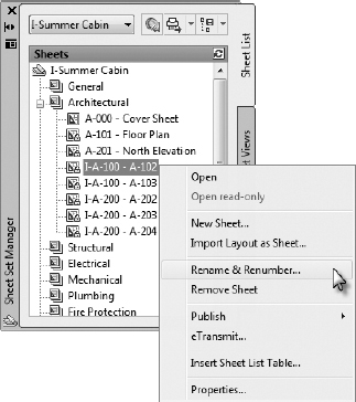
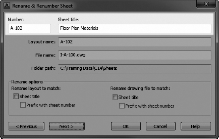
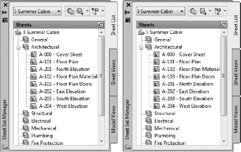
You have now finished setting up your plan set in Sheet Set Manager. While each of the sheets (layouts) has been created, nothing outside of the title block is drawn on the sheets. In the next several exercises, you'll learn about creating and using viewports to look through paper space (layout) into model space at a specific scale.
Adjusting a Viewport's Contents
When using xrefs to reference only the model files necessary for a given sheet, you can take care of much of the layer management by using the XREF command. However, even after you've employed this practice, a quick look at the current A-100 series of plan sheets will reveal a set of sheets that's too cluttered to be useful. A drawing that looks like this would not be acceptable in most production environments, and one of the strengths of AutoCAD is that it enables you to easily adjust existing objects in the drawing.
External references are typically used in the generation of sheets because, when combined with strong file management standards, they can dramatically reduce clutter in drawings. By grouping similar sheets together into a single file, you can perform a large portion of your layer management from model space. Because features such as layer states are much easier to use in model space, you'll generally strive to manage as many layers as possible from model space.
With this in mind, you have a choice to make when any two sheets become dissimilar. Let's use the floor materials layer as an example. It is shown on only one sheet in the entire plan set. Because layers that are frozen or turned off in model space remain that way throughout the entire drawing, you cannot manage that particular layer in the I-A-100.dwg (M-A-100.dwg) model space. There are a couple of ways to address this problem.
First, you may determine that the dissimilarities between it and the other drawings in your set are dramatic enough to justify creating a separate sheet file. Because the layer is used only in a single sheet throughout the entire plan set, you may also choose to categorize your design further by creating a floor finish model file. That way, you wouldn't have to concern yourself with turning that layer off in your other plan sheets, but you could easily reference it in the plan sheet or sheets that needed it.
The other option is to create a viewport override for that layer. Because viewport overrides are hard to track and manage, using them is a less-than-optimal approach; but when used sparingly, they can be the right option in certain situations. As you create your own plan sets, the method you choose will most often be determined based on the time required for each option. For instance, overriding just one layer in 10 viewports will probably take much longer than simply creating another sheet file for that special case.
This section will allow you to see both approaches employed to manage the contents of your viewports. The A-100 series of drawings will require you to create some viewport layer overrides, whereas the layers for the A-200 series will be managed entirely from model space.
Setting the Linetype Scale
Before you begin configuring the layers in each viewport, let's be sure that the layers are displaying correctly. You may have noticed that the rooflines are not dashed, in both model space and paper space. This is because the two variables that control linetype appearance are not set to render lines consistently throughout the entire drawing. To set the linetype scale variables, do the following:
- Make sure that the I-A-100.dwg (M-A-100.dwg) file is open.
- Set the drawing linetype scale to 1 by entering LTSCALE 1 at the command line.
- To configure AutoCAD so that the linetype scale for each viewport is determined by the viewport scale, enter PSLTSCALE 1.
This will ensure a consistent dash length between viewports.
- Finally, to configure AutoCAD to use the current annotation scale in model space to render dashed lines, enter MSLTSCALE 1 at the command line.
When finished, your drawing should look similar to Figure 14.62.

FIGURE 14.62 The Cabin Floor Plan layout after selectively freezing layers in the viewport
Managing the Floor Plan Sheet File
The Floor Plan sheet file is composed of three differing layouts and thus is rather atypical. Each layout, while similar, has numerous dissimilar elements. Much of the layer management affecting the entire drawing has been taken care of through the use of xrefs. That is, since the civil site plan is not referenced in the I-A-100.dwg (M-A-100.dwg) file, there's no need to worry about turning the layers contained within it off.
Even with the civil site plan layers off the table, there are still plenty of layers whose visibility you need to configure in the Floor Plan sheet file. Since many of these exceptions are for a single sheet, much of the remaining layer management for this sheet file will be done using viewport layer overrides.
- Make sure the I-A-100.dwg (M-A-100.dwg) file is open, and switch to model space.
The only layer that's currently visible and that should be frozen in all viewports is the A-AREA-NPLT layer. While it's possible that you already changed the Plot layer property, you'll freeze this layer as well.
- Open the Layer Properties Manager, and freeze the I14A-FPLAYO|A-AREA-NPLT (M14A-FPLAYO|A-AREA-NPLT) layer.
Note how the reference name prefixes the layer name. This allows you to quickly determine to which xref a layer belongs. Conversely, layers without such a prefix belong to the current drawing.
![]() TIP Try selecting the Xref group in the filters section of the Layer Properties Manager. This will display only layers that are referenced in the current drawing. To see a list of only the layers in the current drawing, check the Invert Filter check box in the lower-left corner of the Layer Properties Manager. If you try this, be sure to select the All group and uncheck the Invert Filter check box after you're finished.
TIP Try selecting the Xref group in the filters section of the Layer Properties Manager. This will display only layers that are referenced in the current drawing. To see a list of only the layers in the current drawing, check the Invert Filter check box in the lower-left corner of the Layer Properties Manager. If you try this, be sure to select the All group and uncheck the Invert Filter check box after you're finished.
The Floor Plan Sheet
After adjusting the visibility of layers common to each layout in the current sheet file, you'll begin addressing layer visibility for the individual plan sheets. First up is the Floor Plan sheet A-101. In this plan, you do not want the grid, plan materials, or door label layers to display. You will make these changes in this exercise:
- Make sure the I-A-100.dwg (M-A-100.dwg) file is open, and switch to the Floor Plan A-101 layout.
- Double-click anywhere inside the viewport boundary to enter model space from the viewport.
 Select the Freeze tool (LAYFRZ) found on the Layers panel of the Home tab, and then graphically select one of the floor material hatches on the A-FLOR-PATT layer.
After you select an object on the A-FLOR-PATT layer, that layer is no longer visible on the screen. Because this change was made from within a viewport, the change is applied as a viewport override. This means the A-FLOR-PATT layer will be visible in other viewports in the same drawing but will not display in the viewport on sheet A-101.
NOTE The viewports in layouts are described as floating because they can be moved around. They always reside in the layout portion of the drawing. There is another kind of viewport in AutoCAD called a model space, or tiled, viewport, which is fixed and exists only in model space. If you want more information on this subject, search for the phrase set model space viewports in the AutoCAD help system. For brevity, in this chapter I refer to floating viewports simply as viewports.- Using the Freeze tool once again, select one of the door tags (a circle with a number inside it near the doors).
- Remaining inside the viewport on sheet A-101, open the Layer Properties Manager and locate the 14A-FPLAY1|A-GRID layer.
If necessary, scroll to the right until you find the VP Freeze column.
 Click the icon to freeze the grid layer in the current viewport.
- Close the Layer Properties Manager palette to return to your drawing.
With these layer changes complete, your drawing should look like Figure 14.63.
The Floor Plan Materials Sheet
Similar to the Floor Plan sheet you just finished, you'll apply a series of viewport overrides to the Floor Plan Materials sheet. This time you'll be changing the visibility of the grid, dimension, and door tag layers:
- Make sure I-A-100.dwg (M-A-100.dwg) is open, and switch to the Floor Plan Materials A-102 layout.
- Double-click in the viewport, and use the Freeze (LAYFRZ) tool to select any of the dimensions.
The 14A-FPLAY1|A-ANNO-DIMS layer is frozen in the current viewport only.
FIGURE 14.63 The A-101 Floor Plan layout after the layers in the viewport are selectively frozen
- Use the Freeze tool once again to select one of the vertical gridlines above the floor plan.
Selecting one of these lines freezes the 14A-FPLAY1|A-GRID layer.
- Finally, use the Freeze tool to select one of the door tags to freeze the 14A-FPLAY1|A-ANNO-TABL layer.
- The Drawing Title block is a dynamic block. Click it, and then drag the right end of the horizontal line to the right until it extends underneath the entire title (see Figure 14.64).
FIGURE 14.64 Adjusting the Drawing Title dynamic block
- You may choose to use the PAN command to orient the floor plan better on the Plan Materials sheet.
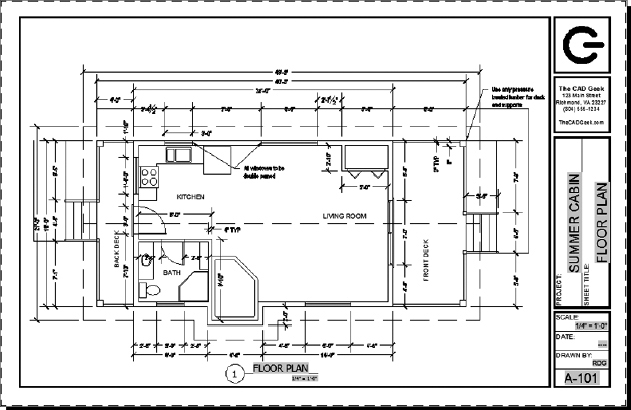

When finished, your drawing should look like Figure 14.65.
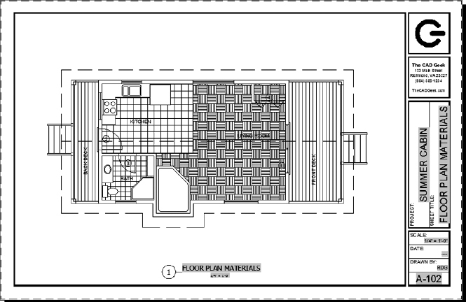
FIGURE 14.65 The A-102 Floor Plan Materials layout after the layers in the viewport are selectively frozen
The Floor Plan Doors Sheet
The Floor Plan Doors sheet is the first layout that requires more than one viewport. Here is a summary of the steps to clean up the drawing:
- Make the A-103 layout active.
- Inside the viewport, freeze the A-ANNO-DIMS and A-FLOR-PATT layers.
- In the status bar, click the Viewport Scale button, and choose
 (1:70).
The viewport zooms out to reflect the smaller scale. To set the metric scale 1:70, it may be necessary to enter ZOOM
1/70 at the command line. - Adjust the length of the horizontal line in the block until it extends underneath the entire title as necessary.
- Select the viewport and, using the grips, adjust it so that it fits more closely to the floor plan.
Your drawing should look similar to Figure 14.66.
- Make the A-ANNO-NPLT layer current.
- Create a new viewport in the lower-left corner of the layout (see Figure 14.67).
FIGURE 14.66 The A-103 Floor Plan Doors layout after the layers are frozen and the viewport is adjusted
FIGURE 14.67 The new notes and table viewports
Refer to the “Creating the Paper Space Viewport” section if you need a refresher.
The viewport displays all the model space contents. Although the view will be labeled as not having a scale, you should create the viewport with a scale of
(1:50). - Select the I14A-FPLAYO.dwg (M14A-FPLAYO.dwg) xref, right-click, and then choose Open Xref from the contextual menu that opens.
This opens the I14A-FPLAYO.dwg (M14A-FPLAYO.dwg) file in a new drawing window.
- Modify the General Notes text box to be a single column, by doing the following:
- Place the cursor just after the first note in the left column.
- Press the Delete key.
- To allow more room in the plan sheet, stretch the 1, 2, 3, and 4 grid-lines to be closer to the cabin.
- Save and close the I14A-FPLAYO.dwg (M14A-FPLAYO.dwg), and then return to the A-103 layout tab in the I-A-100.dwg (M-A-100.dwg) file.
- Copy this viewport, double-click inside the new viewport, and then pan and zoom until the General Notes text fills the viewport.
- Copy the Drawing Title block under the new viewports, and edit the attributes as shown in Figure 14.67.
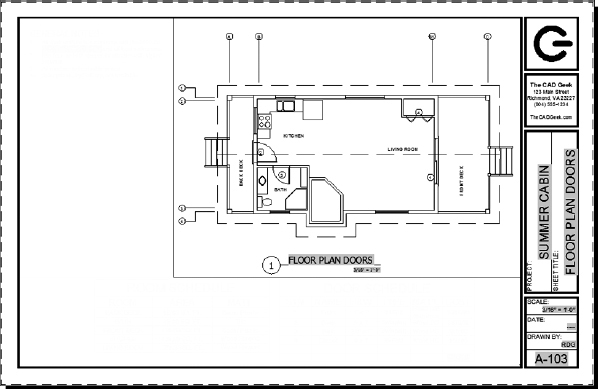
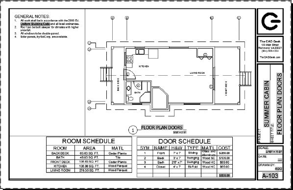
![]() NOTE Most plan sheets require some degree of refinement as they are put together. Learning how to switch quickly between different xrefs is imperative in making these edits in an efficient manner. You'll likely determine a preference, between editing xrefs in place or opening the referenced file, as you gain more experience with the software.
NOTE Most plan sheets require some degree of refinement as they are put together. Learning how to switch quickly between different xrefs is imperative in making these edits in an efficient manner. You'll likely determine a preference, between editing xrefs in place or opening the referenced file, as you gain more experience with the software.
The floor plan drawings for your plan set are now complete. In this section, you learned how to create viewports at a specific scale, manage the layers in those viewports, and import layouts into Sheet Set Manager. In the next section, you'll apply many of these same concepts to setting up your elevation plan sheets.
Managing the Elevations Sheet File
Much of the preceding section was dedicated to managing layers in viewports. Because a handful of layers were viewable in only one or two viewports, you had to spend a sizable amount of time creating viewport layer overrides. It's possible that each of the sheets was different enough to justify creating separate DWG files for each sheet.
In contrast, there's no need to create any viewport overrides in your Elevations sheet file. In fact, your elevations are a perfect example of how xrefs can play a role in layer management for plan sheets. There are no conflicting objects or layers in any of the views you'll create. Consequently, you'll simply verify that all of your elevation layers are visible in model space.
Adjusting the South Elevation Layout
You'll start with the south elevation because it is the only one drawn without rotating the UCS. Consequently, it should be the quickest to set up. Here's how:
- Using Sheet Set Manager, open the A-203 - South Elevation drawing sheet in the I-A-200.dwg (M-A-200.dwg) file.
- Turn on and thaw all of the layers in the current drawing by using the Turn All Layers On (LAYON) and Thaw All Layers (LAYTHW) tools found on the extended Layers panel on the Home tab.
- Pan in the viewport so that the south elevation is centered in the viewport.
- Delete the SOUTH ELEVATION text from the I14A-FPLAYO.dwg (M14A-FPLAYO.dwg) file.
- Adjust the viewport boundary as necessary so that only the south elevation is viewable on the A-203 drawing sheet.
When you're finished, the South Elevation drawing sheet should look like Figure 14.68.
Adjusting the Other Elevation Layouts
The remaining elevations were drawn with a rotated user coordinate system (UCS) so that they appeared in the correct orientation while you were drawing them. However, they are rotated when looking at the drawing in the world coordinate system (WCS). In a similar fashion, you'll modify the view of each viewport by rotating the UCS:
- Make the A-202 (East Elevation) layout active, and double-click inside the viewport.
FIGURE 14.68 The South Elevation layout after layers are frozen and the viewport is adjusted
 To rotate the UCS, do the following:
- Click the View tab, and then click the Z button in the Coordinates panel.
- Enter 90 at the Specify Rotation Angle About Z Axis: prompt.
ENABLE THE COORDINATES PANEL
If the Coordinates panel is not visible from the View tab, do the following:
- Right-click any panel title to display a contextual right-click menu.
- From the contextual right-click menu, choose Show Panels Coordinates.
- To use the PLAN command to rotate the view to match the UCS, enter PLAN.
- Click the Viewport Scale button, choose (1:50), and then exit model space.
- Pan in the viewport so that the east elevation is centered.
- Adjust the viewport boundary as necessary so that only the east elevation appears on the A-202 layout.
- Delete the EAST ELEVATION text.
Your layout should look like Figure 14.69.
FIGURE 14.69 The East Elevation layout after the layers are frozen and the viewport is adjusted
- Repeat steps 1–7 for the two remaining elevation layouts, substituting the appropriate text and values as required. For example, the viewport in the A-201 - North Elevation layout must be rotated 180°, and the A-204 - West Elevation layout must be rotated 270° or −90°.
When the elevations are completed, the A-201 - North Elevation layout should look like the top of Figure 14.70, and the A-204 - West Elevation layout should look like the bottom of Figure 14.70.
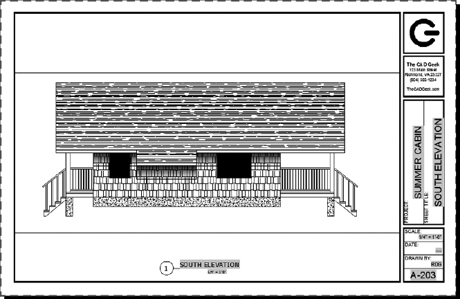
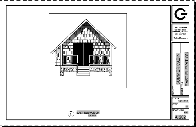
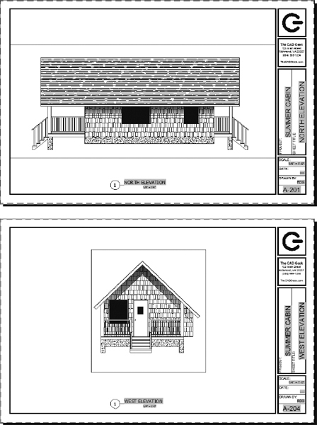
FIGURE 14.70 The North Elevation plan sheet (top) and the West Elevation plan sheet (bottom)
Setting Up the Site Plan Sheet
The site plan should show the cabin plan, the driveway, the access road, and the image, but not the elevations or much of the information shown on the previous layouts. Because of the odd shape of the property line, you'll delete the current viewport, draw a polyline, and turn that polyline into a viewport. Here's how:
- Open the I-C-101.dwg (M-C-101.dwg) sheet file, and make the C-101 layout current.
- Switch to the Model thumbnail by using the Quick View Layouts button in the status bar.
- Make the current layer A-ANNO-REFR, and attach I13C-SPLAYO.dwg (M13C-SPLAYO.dwg) by configuring the Attach External Reference dialog box, as shown in Figure 14.71.
FIGURE 14.71 Attaching the civil site plan to the Site Plan sheet file
- Use the upper-left corner of the deck as the insertion point for the site plan reference (see Figure 14.72).
- Make the A-ANNO-NPLT layer current, and create a new viewport extending from the upper-left corner of the title block to the lower-right corner of the title block.
- Double-click inside the viewport, zoom to the drawing's extents, and then double-click outside of the viewport to switch back to paper space.
FIGURE 14.72 Specifying the site plan insertion point
- With the A-ANNO-NPLT layer still current, start the PLINE (Polyline) command and draw a closed polyline that roughly follows the shape of the property, as shown in Figure 14.73.
FIGURE 14.73 Draw a polyline around the property.
The exact shape isn't important because the viewport scale isn't properly set yet.
- To turn the polyline into a viewport, do the following:
- Click the Layout tab.
- Expand the Rectangular tool, and click the From Object button in the Viewports panel.
- Click the polyline.
 The new viewport displays the model space contents as well as the original viewport.
 - Delete the rectangular viewport.
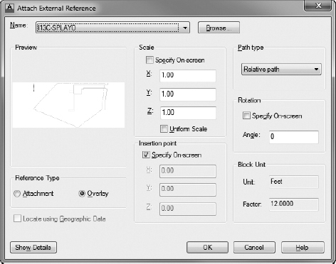
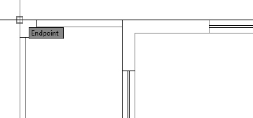
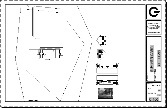
![]() TIP The Create Polygonal button can also be used to draw the viewport directly. However, the Polyline tool provides greater control over the shape of the viewport by allowing arc segments, and it allows the viewports to have a width in situations where they are visible when plotted.
TIP The Create Polygonal button can also be used to draw the viewport directly. However, the Polyline tool provides greater control over the shape of the viewport by allowing arc segments, and it allows the viewports to have a width in situations where they are visible when plotted.
Defining a New Viewport Scale
Scales that use the convention fraction″ = 1′-0″ are said to be using an architectural scale. Site plans generally use an engineering scale, which uses the convention 1″ = number′, where number is a multiple of 10. For this site plan, you'll define a new viewport scale and add it to the Viewport Scale drop-down list.
- Select the viewport, click the Viewport Scale button, and choose Custom to open the Edit Drawing Scales dialog box, as shown in Figure 14.74.
FIGURE 14.74 The Edit Drawing Scales dialog box
- Click the Add button to open the Add Scale dialog box.
The best engineering scale for the site plan, found through experimentation, is 1″ = 20′-0″ (1 = 300). This calculates to a ratio of 1″ = 240″ (1 = 300).
- In the Name Appearing In Scale List box, enter 1″ = 20′ (1:300) but don't press yet.
- In the lower part of the dialog box, set the Paper Units to 1 (1) and the Drawing Units to 240 (300), as shown in Figure 14.75.
FIGURE 14.75 The Add Scale dialog box
- Click OK in each of the dialog boxes to accept the changes and close them.
- Select the viewport again, click the Viewport Scale button, and then choose 1′ = 20″ (1:300). The viewport scale changes to match the scale selected.
- Pan in the viewport, or select the viewport in paper space, and adjust its endpoints so that only the site information is displayed.
- Using the Freeze button or the Layer Properties Manager, freeze the following layers in the viewport only:
A-AREA-NPLT
A-ANNO-DIMS
A-DOOR
A-FLOR-FIXT
A-GRID
A-ROOF
A-ANNO-TABL
A-ANNO-TEXT
A-GLAZ
- Copy the Drawing Title block from another drawing sheet, and change the Viewport Scale to 1″ = 20′ (1:300).
- Create a new viewport, and zoom in to see the referenced image file.
- Copy and edit the Drawing Title block.
Your layout should look similar to Figure 14.76.
FIGURE 14.76 The completed Site Plan layout
- Save the current I-C-101.dwg (M-C-101.dwg), keeping its existing filename.
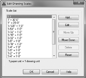
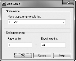

You've made a set of eight drawings, complete with scaled viewports and designated content. In the next section, you will look at a couple of ways to protect the drawings from accidental errors.
Locking and Turning Off Viewports
One of the common errors that you will make when working with viewports is zooming or panning while in a viewport and then failing to return the viewport to its proper appearance. You can prevent yourself, or anyone else, from editing the viewport view by locking the viewport. This feature doesn't prevent you from editing the content of the viewport—just how you access and view it.
Similarly, you may encounter instances where the contents of your viewports do not print, or plot as it's known inside AutoCAD. This is most often the result of a layout being turned off, often by accident. Ensuring your viewports are both locked and turned on are critical steps to managing document sets within AutoCAD.
Locking Viewports
When you execute a pan or zoom while inside a locked viewport, AutoCAD temporarily exits the viewport, pans or zooms the equivalent amount in paper space, and then returns to model space. There is a slight lag in time when panning or zooming with this feature on, but it is much less than the time you may spend correcting, replotting, or reissuing a set of drawings that have viewports at the wrong scale factor. Follow this procedure to lock a viewport:
- Open the I-A-100.dwg (M-A-100.dwg) drawing, and make the A-101 layout active if it's not already.
 Select the viewport, and then click the Lock/Unlock Viewport button next to the Viewport Scale button on the status bar.
 The open lock icon changes to a closed lock. The viewport is now locked.
- Repeat step 2 for all the viewports that show the cabin in the remaining layouts.
Turning Off Viewports
Beyond controlling the visibility of layers in each viewport, you can also turn off a viewport so that all model space objects within it are invisible:
- Make the A-103 - Floor Plan Doors layout current, and then select the viewport that shows the table.
- Right-click and choose Display Viewport Objects; then click No.
The contents of the viewport disappear (see Figure 14.77).
FIGURE 14.77 The Plan Notes layout with the table viewport turned off
You can accomplish the same result in the Properties palette by opening the drop-down list next to the On option in the Misc rollout and clicking No.
- Turn the viewport back on.
- Save this drawing, keeping its existing I-A-100.dwg (M-A-100.dwg) filename.
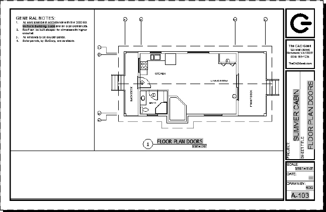
Being able to turn off viewports can be an advantage for a complex drawing with many viewports or for one with a lot of information in each viewport. Remember that even though all the layouts in this drawing are based on one drawing, AutoCAD is drawing at least part of that drawing in each viewport. In a complex drawing, this can slow down the computer, so it's handy to be able to temporarily turn off any viewports on which you aren't working. It's also an easy way to check which objects are in model space and which are on the layout (or in paper space).
You will work with the viewports and layouts again in the next chapter, where you will round out your knowledge of 2D AutoCAD by learning the principles of plotting and printing AutoCAD drawings.
WHAT YOU DO IN MODEL SPACE AND PAPER SPACE (LAYOUTS)
To summarize, here's a partial list of some of the things you do in each of the two environments.
Model Space
You can perform the following tasks in model space:
- Zoom to a scale in a viewport
- Work on the building (or the project you are drawing)
- Make a viewport current
- Control layer visibility globally for the drawing
Paper Space (Layouts)
You can perform the following tasks in paper space:
- Create viewports
- Modify the size and location of viewports
- Use the Viewports toolbar to set a viewport's scale
- Lock/unlock the scale of the display in a viewport
- Turn viewports on or off
If You Would Like More Practice…
Most plan sets for a building project like this one will include a long list of drawing sheets to document all aspects of its construction. Additional sheets might include an overall site plan, a detailed cross section of your kitchen with cabinets and appliances, or even a series of detail sheets documenting how the foundation should be constructed. To create additional sheets (layouts) like these, follow these steps:
- Create a new drawing from scratch, attaching the necessary external references.
- Create another layout for the cabin drawing that has a landscape orientation and is sized to fit a 30″×42″ paper.
- Create four or more viewports: one for an overall site plan and the others for various views of the drawing.
Your new layout may look something like Figure 14.78.
FIGURE 14.78 An additional layout for the cabin project
- Save this drawing as I-A-100-extra.dwg (M-A-100-extra.dwg).
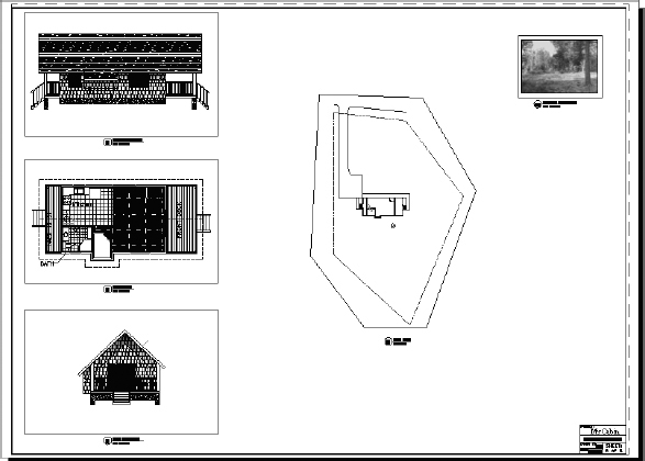
Are You Experienced?
Now you can…
- Create a layout and associate it with a page setup
- Move between paper space and model space
- Create and manage plan sheets by using Sheet Set Manager
- Set up viewports on layouts
- Control layer visibility in individual viewports
- Zoom to a scale in a viewport
- Lock the display of a viewport
- Turn viewports off and on