Black and white printing: facilities and equipment
Vital though the negative may be, it is the final print which people see. Your ability to produce first-class print quality is therefore of utmost importance: good prints cannot be made from poor negatives, but substandard prints are all too easily made from good negatives if you lack the essential skills.
This chapter is concerned with darkroom organization, enlargers and other equipment. It looks at the choice of printing materials, then discusses basic print-processing chemicals and procedures.
Film processing in small tanks can take place almost anywhere (provided you can initially load the tank in darkness). But, like deep tank processing, printing on a professional basis really calls for a permanent darkroom set-up.
There are four basic requirements for a darkroom: (1) it must be light-tight, (2) it needs electricity and water supplies, and waste outlet, (3) the room must have adequate ventilation, and a controllable air temperature, and (4) layout should be planned to allow safe working in a logical sequence, including easy access in and out. Requirements (3) and (4) are just as important as the other, more obvious, facilities. After all, you should be able to work comfortably for long periods, so shutting out light must not also mean shutting out air. If others are using the darkroom too, it is helpful if people can come and go without disrupting production.
General layout
Size naturally depends upon how many people use the room at one time, how long they need to be there, and the work being done. An ‘all day’ printing room for one person might be 20 cubic metres (70 cubic feet) e.g. 2.5 × 3.2 × 2.5 m high, plus 4m2 of floor space per additional user.
The best entrance arrangement is a light-trap or labyrinth (Figure 12.2). This will prevent entry of light, provided it is properly designed and finished in matt black paint. It allows you free passage without having to open doors or pull aside curtains (both can become contaminated and sources of chemical dust and fluff). It is especially useful if you are carrying trays, etc. Equally important, the light trap will freely pass air for ventilation. Elsewhere in the room you should have a light-proof air extractor fan, or better still an air conditioner. Ideally aim for a steady inside air temperature of 20°C (68°F). If you have to use a door instead, make sure there is a light-trapped air grill within it or somewhere in the wall nearby.
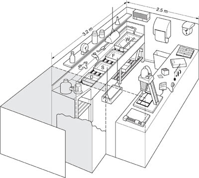
Figure 12.1 A one-person general black and white darkroom, for small-format developing and printing. Note clear separation of ‘wet’ and ‘dry’ areas. Film and print drying take place elsewhere. D: developer. S: stopbath. F: fixer. W: wash
Inside, rigorously divide your space into ‘wet’ and ‘dry’ areas. The wet area should contain a PVC flat-bottomed photographic sink about 6 inches deep with integral splashback, and large enough to hold at least three of your largest print trays. Have one water outlet fed through a hot and cold mixer unit, and positioned sufficiently high for you to fill a bucket or tall container. This, and one or more cold-water outlets, can be threaded to firmly accept a hose coupling to a wash tank or tray. As Figure 12.1 shows, the sink might also have dish racks underneath, a shelf above for storage of small items, and a bench on one side with PVC draining top for larger containers of concentrated developer, fixer, etc.
Have your ‘dry’ bench on the opposite side of the room, far enough away to avoid splashes. Here it can accommodate enlarger, printing papers, negative file, etc., as well as allowing space for loading dry film tank reels. Fit closed storage cupboards below the bench. Have ample power points at bench height along this side for your equipment, plus a sealed outlet higher on the wall near the wet bench for an immersion heater or tempering unit. The latter should be controlled by ceiling-mounted pull switches – you must not be able to operate switches with wet hands.
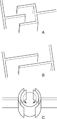
Figure 12.2 Various light-trapped darkroom entrances. A and B layouts are often the easiest way to adapt an existing doorway. C is a commercially made revolving shell you step into, then rotate it around you. Unlike the others, it does not promote ventilation. All labyrinths must have an internal matt black finish
For your working illumination, have one safelight no closer than its recommended distance (page 237) directly above the processing sink. Unless your room is quite small, have another safelight suspended centrally near the ceiling for general illumination (not too near the enlarger, or it becomes difficult to see projected images). If necessary install another small safelight illuminating a wall clock or process timer. Have all safelights controlled by one pull-switch near the door.
For white light, use a ceiling light bulb (not a fluorescent tube, which may glow faintly in the dark). Operate this from a wall-mounted pullswitch, its cord run horizontally along the length of the darkroom at above head height. Then you can reach and switch it on to check results wherever you may be standing in the room.
Choose a wall and ceiling finish inside the darkroom that is as pale as possible, preferably matt white. Provided your room is properly blacked out, generally reflective surroundings are helpful. Your safelight illumination will be more even, and working conditions less oppressive. But keep the wall around your enlarger matt black – like the room entrance, white light will be present here.
Dry benches can be topped with pale-toned laminate and the floor sealed with a seamless, chemical-resistant plastic material. Discourage dust and dirt from accumulating by having a flat surface to walls, with no unnecessary ledges or conduits. Bare cold-water pipes near the ceiling are often a menace, gathering a film of condensation which then drips on to work. Do your drying of pictures (film drying cabinet, print dryer) and the dissolving of any dry chemicals, plus all image-toning processes, out of the darkroom in some separate well-ventilated area.
The enlarger is your most important piece of printing equipment. It is designed like a vertically mounted, low-power slide projector. A lamphouse at the top evenly rear-illuminates your negative, held flat in a slide-in carrier. An enlarging lens at an adjustable distance below the negative focuses a magnified image on to the baseboard of the enlarger, where the printing paper is held flat in an easel or masking frame. Sliding the whole enlarger head (Figure 12.3) up or down the supporting column alters the size of the image on the baseboard. Adjusting the distance between lens and negative alters focus (needed for every change of size). And changing lens aperture by f-stop intervals alters image brightness, just as it does in the camera.
When choosing an enlarger the issues you must decide are (1) the range of negative sizes it should accept, (2) the most appropriate lens, (3) the type of negative illumination, (4) the largest print size you will want to make, and (5) whether – perhaps at some future date – you may want to use it for colour as well as black and white printing.
Negative size
A 35 mm-only enlarger is small and cheaper than one of similar quality accommodating several negative sizes. If you also use rollfilm cameras or are likely to do so, get an enlarger for the biggest format and adapt it downwards for the others (you cannot adapt upwards). As well as interchangeable negative carriers you will need lenses of different focal lengths to get a useful range of print sizes off each format, and if the enlarger has condenser lighting (see below) this requires adjusting too.
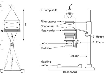
Figure 12.3 Enlarger: basic condenser type. Arrowed solid lines show the path of illuminating light through condensers and negative (N), directed into the lens. Broken lines denote light refracted by lens. Adjustment 1 shifts lens, to focus the image. 2 raises/lowers lamp relative to lens position, adjusting for evenness when needed. 3, movement of the whole enlarger head, alters image size
Enlargers for 4 × 5 in or 9 × 12 cm negatives are much more substantial. It is helpful to keep a separate enlarger for these large formats: many do adapt down for smaller films, but you will find it awkward to keep changing fitments when a mixture of negative sizes is being printed.
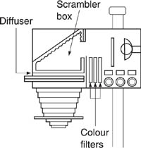
Figure 12.4 Diffuser type enlarger head (this one is also suitable for colour printing). Dials raise filters into the light beam. Light scrambler box scatters and diffuses the illumination to give even light and colour. Reflex layout makes it easier to cool the high-intensity lamp, and reduces headroom
Lens
Enlargers normally come without a lens fitted, as you must choose from a variety of focal lengths and prices. Unlike lenses for cameras, an enlarger lens is designed to give its maximum resolution when the ‘subject’ (in this case the negative) is closer than the image. Typical focal lengths are 50 mm for 35 mm format negatives, 80 mm or 105 mm for rollfilm sizes, and 150 mm for 4 × 5 in. In effect, focal length is a compromise. If it is too long you will not start to get sufficient-size enlargements until the enlarger head is near the top of the column. Too short, and the lens has insufficient covering power (page 85) resulting in negatives appearing to have darkened corners (white on the print), especially at large magnifications. You will also find it is difficult to position the lens close enough to the negative; and when making small prints there is insufficient space below the lens to shade or print in; see page 247.
The wider the maximum aperture, often f/2.8 or f/4 for a 50 mm lens, the easier it will be to see and focus the image. However, prints will very rarely be exposed at this setting because exposure time is then inconveniently short; see page 246. Aperture settings are boldly marked for reading under darkroom conditions, and easily felt by ‘click’ settings at half-stop intervals. Always buy the best enlarger lens you can afford. False economy here can undermine the fine image qualities given by all your camera lenses. Take care not to put fingermarks onto the front, lower, lens surface. And occasionally check the back, upper surface for any accumulated dust.
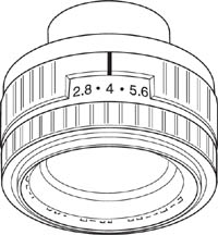
Figure 12.5 Enlarger lens, f/2.8. A large aperture scale and ‘click’ stops make it easy to adjust in the darkroom. Your lens must be of high quality, otherwise all your work is affected
Your film image, held in the negative carrier, must be evenly illuminated. Light from the lamp to the film either passes through a diffuser or a condenser system to achieve this. Many enlargers have a diffuser head which makes the negative appear as though lit by a lightbox or viewed against overcast sky. This soft light design lends itself to built-in colour filtering systems, so heads with dial-in filters for controlling variable contrast paper (page 236) or for colour printing are mainly of this type. The white plastic diffuser located a short distance above the film absorbs a lot of illumination, and to counteract this most enlargers use a bright, quartz-iodide light source. A heat filter and a lamphouse designed with 90° turn of light path prevent negative overheating.
A condenser head gives hard illumination. The lamphouse contains one or more simple but large condenser lenses (diameter exceeding negative diagonal) to gather diverging light from a tungsten lamp and direct it through the negative to focus into the enlarging lens itself. The negative appears to the lens as it would look to the eye if rear-illuminated by a spotlight, or direct sunlight.
This harsh direct light has the effect of making projected images slightly more contrasty than when given diffuse illumination. The contrast enhancement strengthens the appearance of fine detail, and also picks out grain more crisply. (It also shows up scratches and any other surface blemishes on the film.) Regular condenser lamphouse enlargers use an opal tungsten lamp, which one or a pair of glass condensers focus into the lens. The lens therefore sees the negative evenly lit. In a condenser head though you must be able to shift the lamp itself up or down a few inches, or add an extra condenser lens. This is to maintain even light whenever (a) you make an extreme change of print size, or (b) whenever you change lens focal length. (In each instance the negative-to-lens distance changes considerably.)
Both types of enlarger illumination have their virtues. Condenser systems give you a brighter image useful for big enlargements. Diffusers are best for damaged or contrasty negatives. On some models you can change one lamphouse unit for another. As discussed on page 213, it is best to process negatives to a contrast index which suits your particular enlarger. Then you can make fullest use of printing paper (page 232) to adjust contrast up or down to ‘fine tune’ individual pictures.
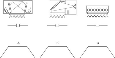
Figure 12.6 Interchangeable diffuser enlarger head designs. Near right: Dual-lamp system for variable contrast paper. Lamps are filtered yellow and magenta by adjustable amounts. (Relate to Figure 12.11.) Centre: Colour head, also suitable for VC paper. Far right: Cold light head. This contains a fluorescent tube and gives lowest image contrast

Figure 12.7 Some enlargers have tilting heads, to correct images with unwanted converging lines
Print size – largest and smallest
Enlargers not only allow you to make prints much bigger than the negative, but reduced size ‘thumbnails’ too. The maximum size magnification you can get from your negative depends on the enlarger lens focal length, and the lens-to-paper distance the height of the column will allow. More precisely, magnification is:
lens-to-paper distance divided by focal length, minus one
For example, if your enlarger column can raise the lens 60 cm above the baseboard, you can make a 30 × 45 cm enlargement from a 6 × 9 cm negative (magnification of ×5) using a 100 mm lens. The taller the column, the bigger the enlargement possible, within the limits of your darkroom ceiling height. For still bigger enlargements the enlarger head may be designed to rotate through 90° so that it projects the image horizontally on to a distant wall. Some bench models turn to work vertically downwards onto the floor; see Figure 12.10.
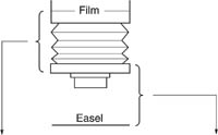
Figure 12.8 The ‘throws’ necessary for a 35 mm enlarger (50 mm lens); and rollfilm enlarger (80 mm) to achieve various image magnifications. Most 35mm standard column enlargers allow the lens to be raised at least 60–70 cm above baseboard
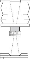
Figure 12.9 Enlargers may also allow you to make reduced size prints, provided the lens will move far enough from the negative, see lower half of table, right. If bellows are too short add a camera extension tube. Check that the image remains evenly illuminated
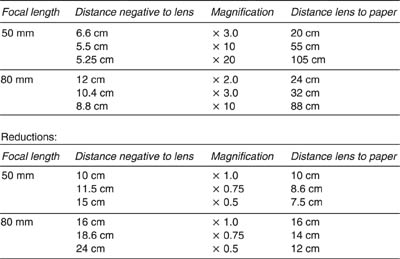
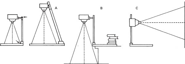
Figure 12.10 Making big enlargements: typical limiting factors are the height of column, and the column base fouling the image area (left). Solutions include (A) angled, extended column and larger baseboard; (B) turning the enlarger head to project from bench down on to the floor; or (C) rotating the head to project on to a distant wall
At the other extreme, for prints smaller than the negative dimensions, you need to be able to lower the enlarger head and position the lens sufficiently far away from the negative; see Figure 12.9. If the bellows will not stretch this far, try fitting a camera-type lens extension ring.
Contrast control filters
In order to alter the contrast of variable contrast printing papers (page 236), all modern black and white enlargers offer some way of tinting the light. This can be a simple filter drawer between lamp and diffuser or condenser. You buy a set of six or more ‘above-the-lens’ acetate filters, Figure 12.12, to use in the drawer one at a time. Changing the filter colour changes the contrast characteristics of your printing paper. Alternatively you can clamp a filter holder below the lens and using a set of smaller gelatin filters alters the light at this point. (Filters must be the more expensive gelatin type, otherwise their use below-the-lens will upset image definition. You must keep these filters completely free of finger marks too.)
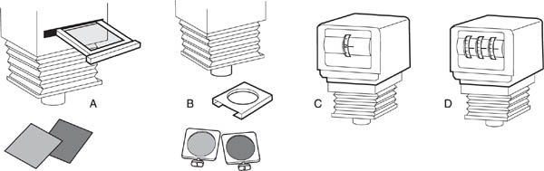
Figure 12.11 Alternative ways to control variable contrast printing paper. A: drawer for (acetate) filters between lamp and negative. B: holder on lens for (gelatin) filters. C: lamphouse with internal dial-in VC filtration system. D: Colour printing lamphouse (see Figure 12.22)
Far more convenient, a variable contrast lamphouse unit allows you to continuously vary filtration, just by turning a numbered dial which moves built-in filters in or out of the light beam above the negative. If you plan later to colour print, a colour lamphouse unit (with yellow, magenta and cyan dial-in filters) will also serve variable contrast monochrome paper, although you may then have to adjust exposure time with each change of filtration; see page 247.
Figure 12.12 A simple set of acetate filters for a variable contrast paper, marked with contrast grade numbers
Other features
Red filter. It is very useful to have a swing-across red filter below the enlarger lens, see Figure 12.3. This will allow you to see the image projected on to the actual light-sensitive paper without actually exposing it – helpful when preparing to shade, print in, or make a black edge line (page 251). The filter is also an alternative means of starting and stopping exposure when you are shading or printing-in, provided you are careful not to jog the image.
Negative carrier. Most negative carriers are ‘glassless’ – holding the film flat between metal frames. You may occasionally need a glass carrier when enlarging a sandwich of two films, which might otherwise sag in the middle. However, sandwiching between glass creates problems because (a) you have four more surfaces to keep clean, and (b) when glass and film are not in perfectly even contact light-interference causes a faint pattern of concentric lines, called Newton’s rings, to appear over the image. Other optional features include metal sliding masks within the negative carrier to block light from any rebate or part of the image you are cropping off (reduces potential flare).
Remote controls for head shift and focusing positioned at baseboard level are a convenience; and an angled column (Figure 12.10) will avoid the column base fouling images when you make big prints. Enlarger movements (a pivoting head and lens panel) are helpful when you must alter image shape without losing all-over sharp focus. This will allow you to give some compensation for unwanted converging verticals due to shooting with a camera pointing slightly upwards. See also digital adjustment of perspective, page 287.
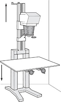
Figure 12.13 Some enlargers have their controls for focusing and raising/lowering located under the baseboard. This is especially useful with column extension units which allow the baseboard down to floor level. The enlarger column is bolted to the wall
Enlarger care
Make sure that your enlarger does not shift its focus or head position, once set. The head must not wobble when at the top of its column, nor the lamphouse and negative overheat because of poor ventilation or use of the wrong voltage lamp. Regularly check that no debris has accumulated on top surfaces of condenser lenses or diffusing panel. (Both add shadowy patches to negative illumination, becoming more prominent in the projected image when you stop down the enlarging lens.) Dust, grease or scratches on enlarging lens surfaces, however slight, scatter light and degrade the tonal range of your prints. This shows mostly as dulled subject highlights, and shadows which print smudged and spread.
Items for the ‘dry’ bench
The enlarger is easiest to use with a timer, wired between the lamp and supply. This will also have a switch to keep the enlarger on for focusing. You must have a masking frame (or ‘easel’) for the enlarger baseboard, with metal masks adjustable to the print size you need. The frame provides a white surface on which to focus the image, and a means of positioning and holding the paper flat during exposure, with edges protected from the light to form white borders. You will probably also need a focusing magnifier (or ‘grain magnifier’). This allows a small part of the projected image to be reflected on to an internal focusing screen which you check through a magnifier (Figure 12.14). Remember that if you plan to use variable contrast paper with an enlarger not possessing a dial-in head, you will also need a set of filters. Other important accessories include tools for shading (page 248), a glass-top contact printing frame (page 244), and a can of compressed air or blower brush for removing any dust or hairs from film and glass surfaces. Some photographers consider an enlarging exposure meter (either an adapted hand meter or an ‘on-easel’ exposure analyser) an essential aid; see page 246.
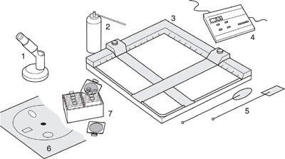
Figure 12.14 Accessories for the ‘dry’ bench. 1: focusing magnifier. 2: compressed air to remove any dust from film. 3: adjustable masking frame. 4: enlarger timer. 5: ‘dodgers’ for shading. 6: card with choice of various shaped apertures for ‘printing-in’. 7: set of mounted gelatin lens filters for VC paper

Figure 12.15 Items for the ‘wet’ side of the darkroom. 1: Trays for solutions, including larger tray as water jacket. 2: graduate, and funnel. 3: Plastic tongs to gently grip a corner of your print when agitating or removing it. 4: Chemicals. 5: Dish thermometer. 6: Hose connector to tap, to dish wash prints (see also Figure 12.28). 7: Clock timer. 8: Heated panel, alternative to water-jacket. 9: Safelight for shelf above sink. 8 and 9 must be designed for safe use in wet surroundings
Have sufficient trays for developer, stop bath, and preferably two fixing baths. You will also want a wash tray or tank suitable for the papers you are using (resin-coated or fibre base). If it is difficult to maintain developer at working temperature, either use a larger tray to enclose your tray of developer and act as a water jacket, or use a dish heater, Figure 12.15. Have a large mixing graduate and containers of concentrated print developer, stop bath, acid fixer and hardener.
A dish thermometer is essential (preferably alcohol-type, for easy darkroom reading), as well as a wall-mounted clock with clear minute and second hands. Two pairs of plastic print tongs – each distinctly different for developer and fixer trays – will help keep your hands out of chemical solutions. Finally, don’t forget a roller towel, and a waste bin you empty daily to avoid darkroom contamination from chemicals drying out of discarded prints. See processing procedure, page 238.
Black and white printing papers differ in their type of base, surface finish, size, image ‘colour’, and emulsion contrast (graded or variable). This offers you an enormous range of permutations, and has done much to keep monochrome photography going as a creative medium.

Figure 12.16 Cross-sections of RC and (single weight) fibre bromide papers. S: supercoat of clear gelatin. E: emulsion. B: whitening baryta coating. A: anti-static layer
Base type
There are two main kinds of paper base – resin-coated and fibre. This difference is more than cosmetic, because their processing and washing times, drying and mounting procedures are different. Resin-coated materials (known as ‘RC’, ‘plastic’ or ‘PE’) consist of paper, sealed front and back with waterproof polyethylene, then face-coated with emulsion and protective supercoat; see Figure 12.16. Because the base cannot absorb solution except along its edges, RC prints wash and dry in about one quarter the time required for fibre papers. When dry, prints do not curl, and have good dimensional stability. Like colour papers, which are all RC based, they are also well suited to machine processing (page 242).
The more traditional type of paper has an all-fibre base. It is first surface coated with a foundation of baryta (barium sulphate) as a whitening agent, followed by an emulsion layer and gelatin supercoat. The total processing cycle for fibre papers is almost an hour, and a glazer is necessary if you want to give glossy paper a highly glazed finish (Figure 12.29). However, final prints are less likely to crack and otherwise deteriorate, especially when displayed over long periods. Fibre prints are also easier to tone, hand-colour, mount and retouch.
In practice, the vast majority of amateur enlargements and commercial prints, especially long runs, are made on RC papers. RC is also convenient for contact prints. But for archival prints and exhibition quality images, fibre paper is still difficult to beat. A further influence is the silver-enriched thick emulsion papers, made only with fibre base, capable of outstanding tone range and aimed at the quality-at-all-cost fine art market.
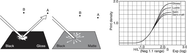
Figure 12.17 How paper surface affects the appearance of maximum black in a print. Left: although when seen from position A, gloss paper reflects a glare spot, from B and other positions black appears intense. Centre: matt paper scatters a little light in all directions – black looks less rich from every viewpoint. Right: paper characteristic curves show the surface effect on maximum possible print density. A typical negative prints with its subject shadow detail more compressed on matt than glossy
5 × 7 in |
12.7 × 17.8 cm |
7 × 9.5 in |
71.8 × 24 cm |
8 × 10 in |
20.3 × 25.4 cm |
9.5 × 12 in |
24 × 30.5 cm |
11 × 14 in* |
27.9 × 35.6 cm |
12 × 16 in |
30.5 × 40.6 cm |
16 × 20 in† |
40.6 × 50.8 cm |
20 × 24 in*‡ |
50.8 × 61 cm |
*Gives four 5 × 7 in
†Gives four 8 × 10 in
‡Gives six 8 × 10 in
Figure 12.18 Standard dimensions of black and white printing paper
Thickness and tint
Regular fibre-base papers are made in single weight (about the thickness of this page) and double weight. Single weight is cheaper, but easily creases during processing if used for prints larger than about 12 × 10 in. A few special-purpose papers are made on lightweight, ‘document’ thickness base or premium-weight (300 gsm) art paper similar to postcard. RC paper is mostly made in so-called medium weight, just slightly thinner than double weight.
At one time, many papers could be bought with a cream or an ivory tinted base instead of white, but with the exception of products such as Kentmere Art Classic, these have tended to go out of favour because they limit the tone range of image highlights. In fact, white bases often incorporate ‘optical brighteners’ which glow slightly under fluorescent or daylight illumination and so further extend image tone range. See also pre-coloured special effects papers, page 255.
Surface finish, size
You have a choice of surface finishes ranging from dead matt, through what are variously called semi-matt, satin, lustre or pearl, to glossy. Simple warm air drying gives RC glossy paper a shiny finish whereas fibre-base glossy dries with a semi-matt surface unless it is put through a glazer after washing.
The combination of base brilliance and surface texture has great influence on the maximum white and black the paper offers you. As Figure 12.17 shows, glossy finish produces richest blacks, when lit correctly. Matt cannot give much beyond a dark grey – which may suit moody, atmospheric pictures. Both papers, however, appear with similarly deep blacks when they are compared wet, so be prepared for changes when prints made on matt paper are dried. Photographs for reproduction should be made on white glossy paper (glazed or unglazed), never on paper with an assertive surface pattern which interferes with the mechanical screen used in ink printing processes; see Advanced Photography.
Figure 12.18 shows the most common printing paper cut sizes. Some papers are also sold in rolls, with widths ranging from 8.9 to 127 cm. As you can see, some larger sheets can be cut down to give exact numbers of a smaller standard size – one reason for keeping a trimmer in your darkroom. Paper is marketed in 10 or 25 sheet packets and (smaller sizes) boxes of 50 or 100.
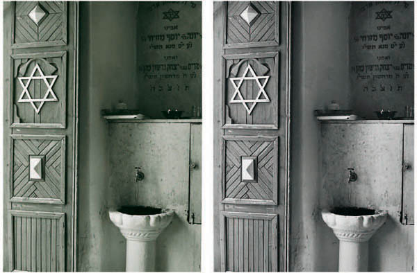
Figure 12.19 Monochrome image ‘colour’. Left: a print on bromide paper. Right: the same negative printed on warm-tone (chlorobromide) paper and processed in warm-tone print developer
Image ‘colour’
Most printing papers have an emulsion containing a mixture of silver bromide and silver chloride light-sensitive halides. Those with a high silver bromide content (bromide papers) give ‘cold’ tones, neutral black in colour, in the recommended developer. Papers with more silver chloride than bromide (chlorobromide) and/or use crystal structuring give a ‘warmer’, slightly browner, black. The warmth of tone is responsive to your choice of print developer, see page 238. The silver chloride content is slower in speed than bromide, and also develops slightly faster – so your chosen length of development makes a big difference to ‘colour’ too.
Choosing between bromide or chlorobromide paper depends mostly on subject and personal preference. The warmer tones of chlorobromide (Figure 12.19) suits landscapes and portraits, and is popular for exhibition work. But it is unsuitable in pictures for regular monochrome reproduction, because printers’ standard black ink will lose the subtleties of warm tone unless printed by four-colour.
Contrast
You can control the contrast of your prints by purchasing different boxes of graded papers – grade 1 (soft), grade 2 (normal), grade 3 (hard), etc., or use just one box of variable-contrast paper and achieve similar changes by filtering the colour of your enlarger light.
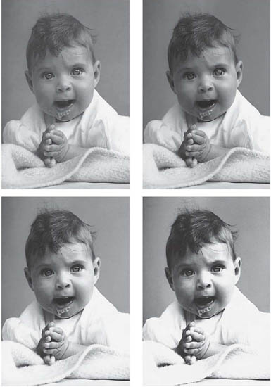
Figure 12.20 Contrast. The same (normal contrast) negative printed on four different contrast grades of the same paper. Clockwise from top left: Grade 1 (soft), grade 2 (normal), grade 3 (hard) and grade 4 (extra hard). Hardest paper gives fewest grey tones between white and maximum black. Grade 1 does not reach maximum black before whites begin to grey with this image – it suits much more contrasty negatives. Variable-contrast paper gives similar results by change of colour filters
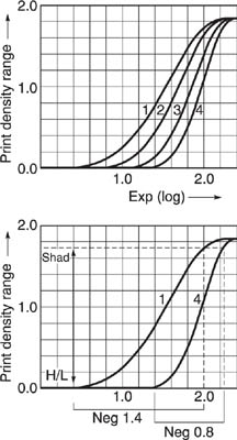
Figure 12.21 Top: the response of four grades of one manufacturer’s bromide paper expressed as characteristic curves. Bottom: a relatively contrasty negative (1.4 density range) printed by diffuser enlarger on grade 1 paper gives a similar result to a lower contrast 0.8 negative on grade 4
Graded papers. With fixed graded papers the lower the number the more greys it can form between maximum black and white. As Figures 12.20 and 12.21 show, soft grades form a relatively gentle ‘staircase’ of tones between these extremes, whereas hard grades rise more steeply and give a harsher and more abrupt range of greys.
Basically, this choice of contrast allows you to compensate for contrasty, or flat, negatives. For example, a fairly harsh continuous-tone negative gives results printed on grade 1 similar to a softer negative printed on grade 4. In practice, choice of grade depends on many factors – type of subject, enlarger illumination, the visual effect you want to achieve, how the picture will be used, and so on. Often by exaggerating contrast beyond how your subject actually looked, you can strengthen a bold design.

Figure 12.22 How filters control variable contrast printing paper. Different proportions of the highand low-contrast emulsions present in VC paper are used according to your chosen colour filtration. Increasingly deep purple or magenta filters absorb more of the green content of the light and so make the paper become more contrasty. Increasing yellow suppresses blue and gives the opposite effect. See Figure 12.12. Durst numbers suggest settings when using a colour head enlarger – combining two filters here keeps the light output the same so that the exposure time remains constant
Bear in mind that the degree of contrast related to grade number – 1, 2, 3, etc. – is not absolutely consistent between one manufacturer and another. Also some papers are made in one or two grades only; others (white smooth glossy, for example) come in six grades.
Variable-contrast papers. These are known as Multigrade, Polymax, or just VC, according to brand. Variable contrast papers carry no grade number. They work by having a mixture of two emulsions. For example, one is contrasty and sensitive only to blue light. The other is low-contrast and sensitized towards the green region of the spectrum. So you can use one of a range of filters from deep yellow (gives grade 0) to deep magenta (gives grade 5) in the enlarger light-path to achieve the contrast you want. Without any filter at all the paper prints as grade 2. If your enlarger has a colour printing head, you can dial in appropriate filters here. See settings, Figure 12.22. With enlargers fitted with special heads for variable-contrast paper you select grade numbers on a dial or baseboard keypad to adjust filtered light beams automatically.
Variable-contrast paper offers you the advantage of not needing to keep an expensive stock of grades as well as different sizes. With a good filtering system you can get the equivalent of five different grades (plus half-grades). Uniquely too, it also allows you to vary contrast across a print, by exposing one area of the image at one grade setting and the rest at a different setting. See shading, page 254.
Choosing a printing paper
All these combinations of features – resin or fibre base; surface; contrast; image colour – are confusing at first. You seem to be spoilt for choice. But when you visit a big photo store or check out the catalogues it’s clear that not all papers are available in all forms. Most papers are made with a white base, glossy or pearl (semi-matt) surface and give a predominantly neutral colour image. If you are a newcomer to monochrome printing it is easiest to learn first with graded paper; next graduate to a variable contrast type, and then explore warm-tone papers.
Safelighting and printing paper sensitivity
Darkroom safelighting should be as visually bright and easy to work under as possible, without of course fogging your paper. The colour filter screening the light bulb or fluorescent tube must pass only wavelengths to which the material is insensitive (Figure 12.24). However, no filter dyes are perfect, and if the safelight is too close, or contains a light source too bright, or is allowed to shine on the emulsion too long, fogging will still occur. See testing project, page 243. Follow the distance, wattage, and maximum safe duration recommendations for your particular safelight unit.
Regular bromide, chlorobromide and multigrade papers are safe under a ‘light amber’ safelight, such as Kodak 0C. Some materials such as lith paper have orthochromatic sensitivity however, to improve otherwise extremely slow speed. They therefore need deep red coloured safelighting as required for ortho films. As Figure 12.24 shows, you can use the same deep red safelight for regular papers, but not the reverse.

Figure 12.23 Panchromatic printing paper. The colour negative (centre) shown as printed on regular black and white bromide paper (left) and (far right) on pan bromide paper. The panchromatic bromide paper gives more accurate grey-tone representation of colours. (For positive colour image see page 162)
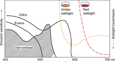
Figure 12.24 Safelight filters. The diagram, right, combines emulsion colour sensitivity curves and filter colour transmission curves. It shows that regular (blue-sensitive) and variable-contrast printing papers are safely handled under ‘light amber’ safelighting. But notice from curve overlap that ortho printing materials, such as lith paper or film, would fog to amber, so they require deep red safelighting instead. Red is also safe for the other two materials, but unnecessarily dark
There are also a few panchromatic printing papers such as Kodak Panalure, designed to give correct tonal response to subject colours when you make black and white prints from colour negatives. Such negatives printed on to regular blue-only sensitive bromide paper make subject reds and yellows too dark, blues too light. In other words, results are like a black and white photograph taken through a blue filter. (Other panchromatic papers are chromogenic types – designed for processing in RA-4 colour paper chemicals in order to suit colour lab print processing machines.)
Panchromatic paper can be handled under a deep green pan film safelight, or is safe under dark amber Kodak 13 safelighting because of its slow speed. Safest of all, work in total darkness (remembering to have an audio timer for processing). Always check the label on any unfamiliar photographic paper for the safelight colour you must use, the recommended minimum distance and the specified lamp wattage.
The facilities on the wet side of your darkroom come into play each time you remove an exposed sheet of paper (Chapter 13) from the enlarger baseboard. Processing monochrome paper follows the sequence develop-stop-fix-wash similar to processing film, but with two important differences. Firstly, because you are using open dishes under safelighting you can watch the image gradually developing up on the paper. This is a fascinating, truly magical, aspect of photography. Secondly, each chemical stage of processing is briefer than the time needed for film; see Figure 12.26.
Developing prints
The most commonly used print developers are Phenidone based (e.g. Ilford PQ) similar to regular film developer, page 211, although in a more concentrated form. (Some ‘universal’ developers serve both film and paper functions, given different dilutions.) Unlike the development of negatives, however, it is important to produce an acceptable image colour, along with good tone values, rich black and clean white. Graininess is not a consideration – paper is so slow and fine-grained that any graininess seen in prints is the enlarged structure of the negative, although often emphasized if printed on contrasty glossy paper.
Developers formulated for use with bromide papers tend to be energetic, and give a good neutral black provided you fully develop. A range of ‘restrained’ developers are made for chlorobromide papers, giving different degrees of warm tone according to formula. See Figure 12.25. It is important that you fully develop prints, at correct temperature. Aim to standardize this aspect of printing – having chosen the paper and developer, do all your controls through exposure manipulation and (variable contrast materials) filtration of the enlarger.
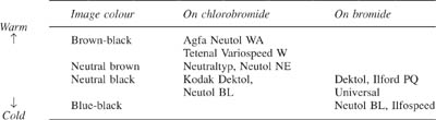
Figure 12.25 Final image colour depends on your choice of print developer as well as type of paper
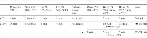
Figure 12.26 Processing sequence for prints using trays. The times given are typical, but you should refer to detailed instructions for each processing solution. The ‘holding bath’ is a rinse tray, used to accumulate prints during a printing session into batches for washing. Times for fibre papers assume single weight unless shown D/W
Dilute an ample amount of developer from stock solution for your printing session and discard it at the end. Take care not to exceed the maximum number of prints your volume of developer or fixer can handle, Figure 12.27. Work with a tray of developer slightly larger than your paper size, and first slide the exposed print under the solution emulsion up, or place it face down in solution and immediately turn it over. Commence rocking the tray gently – for example, by raising each side in turn about 1 cm and lowering it smoothly. Continue this throughout the development period, then lift the sheet, drain for 2–3 seconds and transfer it to the next solution.
If you want to develop several sheets at once, first ensure you have an ample volume of developer solution. Immerse prints at regular intervals, then draw out the sheet at the bottom of the stack and place it on top. Continue this, leafing through the pile continuously (this substitutes for rocking) until development time is up. Then transfer them in the same order to the next bath. To avoid contamination, pick them from the developer with one hand and immerse them in the next tray with the other.
Stop bath and fixing
The solution filling the second tray should be stop bath or, last resort, running water. It has the same development-halting function as with films. If possible use a stop bath containing indicator dye – this changes the solution colour to warn you when it is nearing exhaustion. Next, the paper must be fixed to make remaining halides soluble and so form a permanent image. Unlike film fixing you cannot easily see the creamy halides disappearing from the white paper base, so it is important to adopt an efficient routine. Use an acid hardening fixer, either normal (containing sodium thiosulphate) or rapid (ammonium thiosulphate), diluted to print strength. This can be a single bath which you monitor and discard after, say, 25 prints, 10 × 8 in, per litre. Better still, have two-bath fixing, giving half the recommended fixing time in each. The second bath, which should be fresh solution, is used successively to replace the first bath each time this becomes exhausted and is discarded.
Make sure your prints are agitated from time to time in the fixer. Don’t let them float to the surface. It also helps fixing if you keep the paper face down. Acceptable limits for accumulation of silver salts in the fixer are much lower for papers than for films. So avoid solution that has been used for film fixing – it may still work on films and seem to fix prints too, but has such a concentration of silver complexes that compounds are formed in the paper emulsion that cannot be removed during washing. Don’t overfix, either. Rapid fixer, in particular, can begin to bleach image highlight detail, and with fibre papers sulphur by-products can bond themselves into the base. From here they will not wash out, and start to attack the silver image perhaps months or years later.
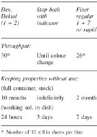
Figure 12.27 Typical working life of some black and white print processing solutions
Time and temperature
Typical times and temperature tolerances for dish processing are shown in Figure 12.26. Notice the timing difference between RC and fibre papers. Most RC papers incorporate developing agent in the emulsion – inert, but activated when placed in the regular developer solution. Here it is immediately able to start acting on exposed halides, so this arrangement shortens the period needed for development to about 45–60 seconds, making such papers suitable for machine processing (page 242). With all RC papers, the stages following development are shorter too. The emulsion absorbs new solutions quickly as the plastic base carries over so little of the previous chemical.
Only when you have sufficient experience in judging the image under safelighting can you begin to develop ‘by inspection’, and so make slight corrections for exposure by adjusting the development time within acceptable limits (±30 per cent at most). This is really practical only with those fibre and RC papers offering longer developing times. Insufficient development gives you grey, degraded blacks; overdevelopment also begins to lower contrast with papers incorporating developing agent. So it is in your best interests to try to work strictly to the recommended time and temperature.
Washing prints
RC paper needs a relatively short period of washing, provided it is efficient. Remember that sheets are plastic, so you simply need to keep a flow of water over the emulsion surface. A shallow flow tray, or a wash tank fitted with a print rack (Figure 12.28), will complete washing in about 3 minutes. If prints are just left in running water in an ordinary tray or sink for 3–4 minutes make sure they are agitated, not allowed to clump together.
When washing fibre paper however you must allow time to let byproducts soak out of the porous base as well. It will help greatly if you first place prints in hypo clearing agent (typically 2 minutes treatment) prior to washing. This agent causes an ‘ion exchange’ helping to displace the fixer more readily from all layers of the material. The best wash arrangements are either soak-and-dump, using a siphon to completely empty a dish or sink at regular intervals, or some form of cascade system. Typical wash time is 30 minutes for single weight, 40 minutes for double weight. This can be reduced to one-third or less if hypo clearing has been used. See also archival print processing, page 294.
Wash water temperature is not critical, preferably 10–30°C for RC paper, 18–24°C for fibre type. Excessive soaking – say several hours at 24°C, or overnight at any temperature – may cause emulsion to start parting company with the base. It may even begin gelatin disintegration, especially if you used a non-hardening fixer.
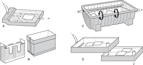
Figure 12.28 Print washing equipment. A: small volume tray washer designed for RC papers. B: plastic rack and wash tank for RC. C: tank for fibre base papers. This uses water flow to keep prints apart. D: cascade system. Newly processed prints go into the lower sink, are later transferred to the upper sink for the second half of their wash period. The tube pushed into each waste outlet maintains solution level. C and D suit both types of paper
Drying
Your print drying method is important because it has to give a flat, unbuckled finish; it can also affect print surface. The simplest but slowest technique is ambient air-drying. You must first remove surplus water from back and front print surfaces with a rubber squeegee. Then leave prints on absorbent material such as cheesecloth or photographic blotting paper, face up for RC paper, face down (to reduce curl) for hardener-treated fibre prints. Or you can peg them on a line with plastic clothes pegs at top and bottom – fibre prints in pairs back-to-back, RC prints singly. Drying may take several hours at room temperature.
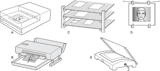
Figure 12.29 Print drying. A: Fan assisted warm air dryer, for up to two RC prints at a time. B: Fast, hot-air dryer for RC paper only; print must be inserted covered by a film of water, direct from tray. C: Ambient air-drying, using muslin racks or line pegging (D). E: flat bed heated dryer, with glazing sheet for fibre base glossy paper
To speed up the drying of RC prints, use a heated air drying unit, Figure 12.29, or blow them over with a hair dryer (temperature not exceeding 85°C). Better still, pass the thoroughly wetted prints through a roller-transport hot air RC dryer, designed to deliver dry prints in about 10 seconds.
For fast drying of fibre prints, have a flat-bed glazer/dryer, which uses tensioned canvas to press the paper against a heated metal surface. Placing the back of the print towards the heat gives a final picture surface similar to air drying. To get a shiny finish with glossy fibre paper, you squeegee it face down on to a polished chrome glazing sheet, so the gelatin supercoat sets with a matching mirror-like finish when dry. Unless this is done, glossy fibre papers will dry semi-matt. You can at any time remove the glaze from fibre paper by thoroughly resoaking the print and then drying it faced the other way. (Avoid hot-glazing other fibre paper surfaces, and RC prints of any kind. The former take on ugly patches of semi-gloss, the latter will melt at 90°C or over and adhere firmly to the metal and canvas.)
Manufacturers of premium fine-art fibre papers recommend air drying unless you are glazing glossy. The fact is, anything touching the emulsion during drying is a potential source of damage. There is always a risk, when using a glazer for other fibre paper surfaces, that the canvas will either mark the final emulsion finish, or chemicals previously absorbed from drying insufficiently washed prints will transfer into your print. However, this is still the best drying method for thin-base prints, which tend to curl badly if air-dried instead.
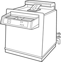
Figure 12.30 Black and white print processing machine. A rollertransport unit that delivers washed, dried RC prints. Exposed prints are fed in at the front, delivered back onto top of machine. This unit is located wholly in the darkroom
Machine processing
Resin-coated papers lend themselves to automatic machine processing. Units are often bench or floor standing within the darkroom, Figure 12.30. You feed your exposed print in through motorized rollers and the equipment feeds them through tanks of regular developer, rinse, fixer, and wash; then passes them directly through an RC paper dryer. Such machines are expensive but produce a fully processed dry print in about 2 minutes – or up to 450 prints, 10 × 8 in size, every hour.
A processing machine can be economically justified when there are several people working on enlargers in a constantly used darkroom – it effectively does away with the wet bench. Without sufficient through-put however the transport system and stored chemicals may deteriorate, resulting in faulty prints.
Summary. Black and white printing: facilities and equipment
1 |
Find out the range of print sizes you can make. Physically check the upper and lower limits of image magnification your lens(es) and enlarger design allow, while still maintaining an evenly illuminated negative. Remember the use of extension tubes. |
2 |
Test your darkroom safelight. Set up a typical negative in the enlarger (preferably including some pale tones, such as grey sky). With safelights on, make a correctly exposed print, including masked white borders, and tray-process it normally. Call this print A. Next expose and process another print exactly the same way but with the safelight off. Call this B. Now expose a further print, without the safelight on. Before processing, position it emulsion-up on a large card placed on top of the developer tray. Cover 25 per cent of the print with opaque card and switch on the safelight. After 1 minute cover 50 per cent, after 2 minutes 75 per cent, then leave the final 25 per cent a further 4 minutes before switching the safelight off again. (This gives you tests of 0, 1, 3 and 7 minutes respectively). Call this print C and process it in darkness, the same way as print B. Wash and dry your prints and analyse results. If all three prints are identical your safelight conditions are safe. If A shows lower contrast, or greying highlights or borders relative to B, you have serious fogging. Confirm safelight colour, check for bleaching or light leaks, and reduce intensity or increase distance. If C shows highlight degradation in any of the fogging test strips it carries, remember to avoid exposing paper for this long. If such a period is too short to be acceptable, take corrective measures. Finally test again. |