
8
The Host Controller Interface
Some Bluetooth systems will have the baseband and Link Manager on one processor with higher layers such as L2CAP, SDP, RFCOMM, and applications running on a separate host processor. A Bluetooth PCMCIA card for a PC could be implemented like this with the Link Manager and baseband in the PCMCIA card, and the higher layers on the PC’s processor.
In systems where the higher layers are run on a host device’s processor and lower layers on a Bluetooth device, an interface is needed between the higher and lower layers. The Bluetooth standard defines the Host Controller Interface (HCI). By making this a standard interface, it is possible to mix and match higher and lower layers, so, for instance, one set of higher layer software on a PC could run with PCMCIA cards from different manufacturers.
A device such as a Bluetooth card for a PC may use the HCI to separate upper and lower layers for many reasons:
- Hosts such as PCs have spare capacity to handle the higher layers, allowing the Bluetooth device to have less memory and a less powerful processor or DSP, thus reducing its cost.
- The host device can sleep and be awoken by an incoming Bluetooth connection.
- The HCI interface is useful for test and type approval of Bluetooth devices.
Figure 8–1 shows how the Bluetooth Protocol stack may be split into two parts linked by the Host Controller Interface.
Figure 8–1 Position of the Host Controller Interface in the Bluetooth protocol stack.
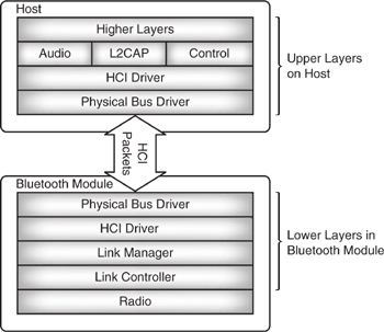
Why not move the whole stack onto a host’s processor? This could be done, but Bluetooth’s slot timing means that the host would have to be able to respond within microseconds to interrupts from the Bluetooth radio. Although hosts may have spare MIPS, most would not be able to guarantee that the processor would be available when it is needed. Therefore, it makes sense to keep the lower time critical layers on a separate processor, which can guarantee a fast response.
Standardising the Host Controller Interface allows drivers to be written which can be used with a variety of Bluetooth modules from different manufacturers. It also provides a standard test interface which can be used to exercise the radio and lower portions of the Bluetooth stack.
It is possible to have Bluetooth systems where all layers of the protocol stack run on one processor; a headset is an example of such a system. Headsets need to be small, inexpensive, light, and low power. Running the whole Bluetooth stack on one processor fits in well with these requirements. These single-processor devices still need to support an HCI for test purposes, however.
In this chapter and throughout this book, all HCI commands and events are prefixed with “HCI_.” In the standard this is not done, but it is done here because in the diagrams which show several layers of the protocol stack interacting, the prefix makes it easier to identify the HCI layer. This chapter covers many of Bluetooth HCI commands, but excludes those covered in the chapters on security, low-power modes, quality of service, and testing (see Chapters 15, 16, 17 and 19).
8.1 Hci Packet Types
The Bluetooth standard for the Host Controller interface (HCI) defines the following:
- Command packets used by the host to control the module.
- Event packets used by the module to inform the host of changes in the lower layers.
- Data packets to pass voice and data between host and module.
- Transport layers which can carry HCI packets.
Figure 8–2 shows the directions the HCI packets flow.
Figure 8–2 The three types of HCI packets.

8.1.1 HCI Commands
HCI commands are used by the host to control the Bluetooth module and to monitor its status. Commands are transferred using HCI command packets.
The HCI command packet structure is shown in Figure 8–3. It begins with a 2 byte OpCode identifying the type of the command. The first byte of the OpCode is the OpCode Group Field (OGF), which identifies a group of commands. The second byte holds the OpCode Command Field (OCF) and identifies a command within the group.
Figure 8–3 HCI command packet.
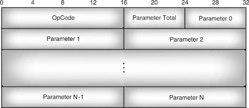
The OpCode is followed by a single byte field giving the length of the following parameters in bytes. The parameters themselves come next, and each occupies an integral number of bytes. Note that since the parameters are not all single bytes, the parameter total length need not necessarily give the total number of parameters.
If a command can complete immediately, an HCI_Command_Complete event is returned immediately to indicate that the command has been dealt with. One exception to this use of HCI_Command_Complete is when it is a reply to an HCI_Reset command. After a full reset, the module can’t tell whether it has reset because it was just powered on, or whether it has reset because it received an HCI_Reset command. This means that it would be impossible for the HCI_Command_Complete to be sent after the reset (when the command has really completed), so instead, an HCI_Command_Complete is sent to tell the host that the command has been received and will be acted upon.
Between version 1.0b and 1.1 there was a change in the specification of the HCI_reset command: In version 1.0b it reset the HCI transport layer, so that for instance a USB implementation of HCI would re-enumerate after an HCI_reset. In version 1.1 the specification was changed so that LM and layers below are rest, but the HCI transport layer remains unaffected. Also in version 1.1 the host is allowed to send commands as soon as it has received the HCI_Command_Complete event associated with the reset, so any implementations which will be unable to handle further commands whilst processing the reset should delay the HCI_Command_Complete until they are ready to handle further commands from the host. This change makes implementation easier for host programmers, as they don’t have to cope with the HCI transport layer restarting, but it makes implementation more difficult for the lower layers as they must implement the rest in software (a full hardware reset would reset the HCI transport later along with the rest of the stack).
If a command can’t complete immediately, an HCI_Command_Status event is returned immediately, and another event is returned later when the command has completed. An example of such a command is the HCI_Inquiry command, which starts an inquiry. The result of the inquiry can’t be returned until the inquiry has finished, and this will take some time, so an HCI_Command_Status is returned immediately to acknowledge that the HCI_Inquiry command has been received. Later, an HCI_Inquiry_Complete event is returned.
8.1.2 HCI Data Packets
HCI data packets are used to pass both data (ACL) and voice (SCO) information across the HCI. Different packets are used for ACL and SCO data.
Figure 8–4 shows the HCI data packet used to transfer ACL data. The fields in this packet are as follows:
Figure 8–4 HCI ACL data packet.
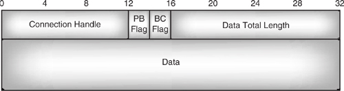
- The connection handle identifies the ACL connection for the data.
- The Packet Boundary (PB) flag identifies whether the packet data carries the start of a higher layer L2CAP packet, or is a continuing fragment of an L2CAP packet.
- The Broadcast (BC) flag identifies point to point data from broadcast data and discriminates between point to point, active broadcast (for active Slaves) and piconet broadcast (for active and parked Slaves, hence must be sent in beacon slots). Note that sniffing slaves are not guaranteed to receive either type of broadcast.
- Data total length gives the length of data in bytes.
The data total length field is 2 bytes, so the maximum theoretical size of data an HCI packet could carry is 65,535 bytes. However, many Bluetooth modules will not have buffers large enough to receive this size packet. An HCI command, HCI_Host_Buffer_Size, can be used to limit the maximum size of ACL data packet which can be transferred, but every Bluetooth module and host are required to support packets with a data length of up to 255 bytes.
Figure 8–5 shows the HCI packet used to transfer SCO (audio) data. Its structure is very similar to the ACL packet with a few differences:
Figure 8–5 HCI SCO data packet.
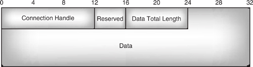
- There are no PB or BC flags; their places are reserved.
- The data total length field is only 1 byte, restricting the data field to 255 bytes.
The reason for the smaller length field is that the SCO link is intended for two-way audio; if too much data is passed in one packet, it increases the time lag between the ends of the SCO link.
8.1.3 HCI Event Packets
The format of HCI event packets is similar to HCI command packets, as shown in Figure 8–6. They carry an event code identifying the event. This performs a similar function to the OpCode field, which identifies HCI commands. Like the command packet, there is a field giving the total length of the parameters, followed by a list of parameters.
Figure 8–6 Structure of an HCI event packet.

The HCI_Set_Event_Mask command is used to tell the Bluetooth module which events it wishes to know about. This command can switch on or off any events except the HCI_Command_Complete event, the HCI_Command_Status event, and the HCI_Number_Of_Completed_Packets event. These three events cannot be switched off because they are needed for flow control (see section 8.3, Flow Control).
HCI_Set_Event_Filter command is also used to disable reporting of events, but rather than simply switching events on and off, it uses event filters to specify which modules the host is interested in for inquiries and connections.
The Inquiry_Result_Filter command allows the host to choose whether to see inquiry events from any module, from only a specified device classes, or from only a specified device.
The Connection_Setup_Filter command allows the host to make the same choices for connections: the host may choose to connect to any device, to devices with a specific device classes, or to a specified device.
8.2 The Hci Transport Layer
A transport layer is needed to get HCI packets from the host to the Bluetooth module.
Bluetooth defines three transport layers:
- USB—Universal Serial Bus.
- RS-232—a serial interface with error correction.
- UART—Universal Asynchronous Receiver Transmitter, a serial interface without error correction.
8.2.1 USB Framing
USB maps the different types of HCI packets onto the USB standard’s different logical endpoints:
- HCI commands—USB control endpoint.
- HCI ACL data—USB bulk endpoint.
- HCI SCO data—USB isochronous endpoint.
- HCI events—USB interrupt endpoint.
A bulk endpoint is used for ACL data for two reasons: first, it allows many 64-byte USB packets to be transferred in each millisecond long USB frame, so it is fast enough for ACL data; second, because it has the ability to detect and correct errors, so it assures that the data arrives uncorrupted.
The isochronous endpoint transfers SCO data directly into the host’s SCO FIFO buffers. If the FIFO buffers are full, the new SCO data simply overwrites the stale data. In accordance with the USB specification, the isochronous endpoint should be set up with an interval of 1 ms. There is no error correction across this endpoint, so SCO data may be corrupted.
The interrupt endpoint is used for events. Using a 1 ms interval ensures that events are transferred promptly across the USB interface.
To allow the correct USB driver to load, a USB class code has been assigned to Bluetooth devices specifying class, subclass, and protocol codes as follows:
- bbDeviceClass = 0xE0 (wireless controller).
- bbDeviceSubClass = 0x01 (RF controller).
- bbDeviceProtocol = 0x01 (Bluetooth programming).
Bluetooth is intended to be a low-power protocol for battery-operated devices. A USB host controller will check memory to see if it has to do anything every millisecond. This can adversely affect power saving on hosts. For example, a notebook processor with an active USB Bluetooth module will not be able to drop into the C3 low-power state. This will cause significantly shorter battery life. More information on USB is available from http://www.usb.org.
8.2.2 Serial Transport Layers
RS-232 and UART are both serial links. They both include framing to identify the packet type as follows:
- 0x01—HCI command packet.
- 0x02—HCI ACL data packet.
- 0x03—HCI SCO data packet.
- 0x04—HCI event packet.
UARTs are not expected to cope with errors or have to negotiate link configuration, but the RS-232 protocol needs to cope with these, so RS-232 also provides:
- 0x05—error message packet.
- 0x06—negotiation packet.
On the UART transport layer, the packet indicator identifying the packet type is sent immediately before the packet. The HCI packet’s length field can be used to work out the boundaries of the packets, and hence when to expect the next packet indicator.
The UART transport layer uses null-modem connections as shown in Figure 8–7. Transmit data (TXD) is connected to receive data (RXD), and Clear To Send (CTS) is connected to Ready To Send (RTS).
Figure 8–7 Connections for HCI UART transport layer.

On UART interfaces, it is possible for the UART’s buffers to run out of space, so RTS/CTS flow control is used to flow control the UART interface. CTS set to 1 stops the other end from sending; CTS set to 0 gives permission to send. Bluetooth defines a 3 ms delay between setting RTS to 1 and data flow stopping, so this time lag should be taken into account when setting RTS.
RS232 links are subject to errors, so they are slightly more complex than UART links. The same single byte packet type indicators are used, but a single byte sequence number is added to allow retransmissions to be identified. The sequence number is incremented on every packet except for retransmissions, so if it stays unchanged, the receiving side knows the packet is a retransmission.
Figure 8–8 shows the structure of HCI packets used on RS232 links.
Figure 8–8 RS-232 HCI packet frame.
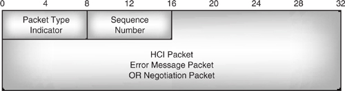
The Bluetooth HCI transport layer initialises with a set of default parameters:
- Baud rate = 9600 bps.
- No parity.
- 8 data bits.
- 1 stop bit.
- Protocol mode = 0 × 13 (HDLC like framing, with COBS/CCITT-CRC).
The host and Bluetooth module should begin by negotiating agreed parameters for these variables and also the value for Tdetect, the time to stop sending after CTS is set. These values can also be renegotiated later if required. The negotiation packets are used to negotiate these values.
COBS/CCITT-CRC delimits frames with 0 7E, and immediately before the final delimiter includes a CRC to allow error checks. When the receiving end detects an error, it sends an error packet back. This identifies the sequence number of the packet with the error, and the type of the error (chosen from: FIFO overrun, parity error, framing error, CRC error, missing sequence number, or missing retransmission packet). The transmitting end can then retransmit the packet with the error.
8.3 Flow Control
Some HCI transport interfaces offer data rates much larger than the data rate across the Bluetooth radio and air interfaces, so a host can pass data down faster than it can be transmitted out of the module. The Bluetooth module could simply buffer the data until it is ready to transmit, but for modules such as Bluetooth PC cards, the host will have far more memory available than the Bluetooth module (just adding more memory is not a sensible solution as it would make the module far more expensive). So if a Bluetooth module can’t transmit data fast enough and doesn’t have space to store it, what’s the solution?
One possibility would be to slow down the HCI transport interface, but that would slow down commands as well as data, and besides, the data rate on air is variable according to interference and the capabilities of the device at the far end of the Bluetooth link. So, a mechanism is needed to slow down data transport across the HCI only when the Bluetooth module’s buffers are overloaded and to allow the HCI transport layer to run at full speed the rest of the time. Bluetooth solves this problem by providing flow control of the HCI.
8.3.1 Command Flow Control
Each time a command is sent to the Bluetooth module, the module responds with a HCI_Command_Complete or HCI_Command_Status. HCI_Command_Complete is used if the command can be executed immediately, otherwise HCI_Command_Status is used and HCI_Command_Complete is sent when the command has completed (see Figure 8–9).
Figure 8–9 Message sequence charts for HCI command flow control.
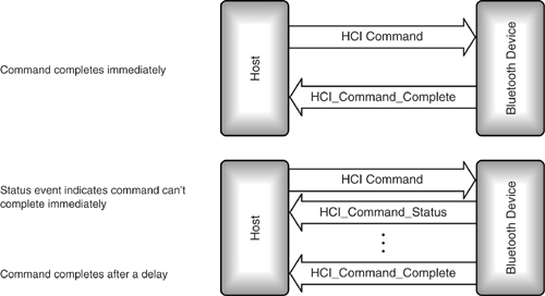
When the system is first switched on, the host may only send one command until it has received an HCI_Command_Complete or HCI_Command_Status event. These events contain a Num_HCI_Command_packets field, which tells the host how many command packets the Bluetooth module can buffer. The host may then send that many command packets to the Bluetooth module.
For instance, if the Num_HCI_Command_packets parameter is 3, then the host can send 3 commands to the Bluetooth module without waiting for a response. Even though the Bluetooth module may be buffering several commands at the same time, it must deal with them in the order in which they were sent.
8.3.2 Flow Controlling Data from the Host
A different mechanism is used for flow controlling data across the HCI interface. The HCI_Read_Buffer_Size command is used to find out how much buffer space the Blue-tooth module has. The Bluetooth module replies with the numbers of SCO and ACL packets it can buffer, and the maximum size of HCI SCO data and HCI ACL data packets.
Typically, a module will not buffer much SCO data because SCO data should pass regularly through the protocol stack with as little latency as possible. ACL data is usually more bursty in nature, so modules can buffer ACL data without adversely affecting the application.
Once the host knows how many SCO and ACL packets the Bluetooth module can buffer, it can send up to that number of packets across the HCI to the Bluetooth module. Once the host has sent enough packets to fill up the module’s buffers, it must wait for the module to tell it that more space is available.
A Bluetooth module tells its host that it has buffers free for more data packets by sending the HCI_Number_Of_Completed_Packets event. This event tells the host how many HCI data packets have been removed from the module’s buffers since the last HCI_Number_Of_Completed_Packets event was sent. The packets may be cleared from the module’s buffers either because they have been transmitted or because they have been flushed.
The parameters in the HCI_Number_Of_Completed_Packets event include a list of connection handles and a number of completed packets for each handle, so that if several connections are in use, the host is informed of the activity on each connection separately.
It is up to each implementation to decide how often the HCI_Number_of_Completed_Packets event is sent. At the extreme, it could be sent after each packet transmitted, or the module could wait until its buffers are completely empty before sending the event.
SCO data’s synchronous nature means that every time a SCO slot becomes available, either a SCO packet is sent or discarded. This means that the module telling the host the number of completed packets on a SCO channel is really a waste of time; the host could just figure out the numbers for itself. Because of this, Bluetooth provides an HCI_Write_SCO_Flow_Control_Enable command, which stops the Bluetooth module from sending any information on SCO channels in the HCI_Number_of_Completed_Packets events (the HCI_Read_SCO_Flow_Control_Enable can be used to find out how SCO flow control reporting has been set). Note that the command does not actually have any effect on the flow of data across the baseband SCO channels; it only affects whether the host is informed when SCO data buffers are available.
8.3.3 Flow Controlling Data from the Bluetooth Module
Usually there will be no problem with the host accepting data as fast as the Bluetooth module can send it. However, some hosts with limited processing capacity such as mobile phone handsets may not be able to accept data at full rate, and may need to flow control the Bluetooth module. Flow control of the Bluetooth module is switched on with the command HCI_Set_Host_Controller_To_Host_Flow_Control.
The HCI_Host_Buffer_Size command is then used to notify the module of the host’s buffering capabilities. It contains the numbers of SCO and ACL packets the host can buffer, and the maximum size of HCI SCO data and HCI ACL data packets.
The host uses the HCI_Host_Number_Of_Completed_Packets command to tell the Bluetooth module how many buffers it has freed on each connection. This command may be sent at any time and is not affected by the usual flow control mechanisms.
When connections are closed, all untransmitted packets are flushed. Since both the host and Bluetooth module know that this happens, the flushed packets are not mentioned in the next HCI_Number_Of_Completed_Packets events.
8.4 Configuring Modules
HCI provides configuration commands to set up the characteristics of the local module. Since these commands don’t involve the Bluetooth link, they return immediately with an HCI_Command_Complete event.
8.4.1 Version and Features Information
Before a module can be used at all, it is crucial to know its capabilities and which version of the standard it supports. The HCI_Read_Local_Version_Information returns:
- A status byte—zero if the command succeeded, no zero for errors.
- HCI version.
- HCI revision.
- LMP version.
- Manufacturer name.
- LMP sub-version.
In versions before 0.7, the parameters were different:
- HCI version.
- HCI revision.
- LMP version.
- LMP revision.
How does the host get version information when the version information command changes between versions? It is possible to figure out whether the parameters are from pre or post version 0.7 as the earlier version has a shorter parameter list. So when interpreting this command, the parameter total length field should be taken into account (see Figure 8–6). The only version 0.7 devices available were development kits, and these can be upgraded to later versions; so in practice, encountering version 0.7 parameters is unlikely to cause problems for commercial Bluetooth products.
The HCI_Read_Remote_Version_Information mirrors the HCI_Read_Local_Version_Information, but returns the information on a connected device. The device is specified by a connection handle.
8.4.2 Local and Remote Name Request
Every Bluetooth device has a friendly name which is a UTF-8 encoded string up to 248 bytes long. (If the name is less than 248 bytes long, it is terminated with a NULL 0x00.) The HCI_Read_Local_Name command can be used to find out the friendly name of the local module. To change the local module’s friendly name, use the HCI_Change_Local_Name command. Friendly names are transmitted starting with the first byte of the name. This is contrary to the usual rule of sending multi byte parameters in little Endian Format (least-significant byte first).
The HCI_Remote_Name_Request is used to request the friendly name of a remote device. This command can be used even if there is no current connection to the device, in which case, the device first establishes a connection, then uses the LMP_name_req to get the name of the remote device. So that the device can establish a connection, the parameters required are passed in the HCI_Remote_Name_Request. These are the BD_ADDR, Page_Scan_Repetition_Mode, Page_Scan_Mode, and Clock_Offset.
It may take some time to establish a connection and get the remote device’s name, so when the module receives the HCI_Remote_Name_Request, it acknowledges it with an HCI_Command_Status event. Once the remote name has been obtained, the module sends an HCI_Remote_Name_Request_Complete event containing a status field indicating success or a reason for failure, the BD_ADDR of the device, and its friendly name. The most common reason for failure in the status field is likely to be maximum number of connections, which indicates that there are insufficient resources to establish a connection to the remote device.
8.4.3 Class of Device
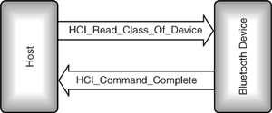
An example of a command which generates an immediate HCI_Command_Complete event is shown in Figure 8–10. The host sends an HCI_Read_Class_Of_Device request so that it can find out the setting of the device type which is passed in the FHS packets used to respond to inquiries. The Bluetooth module will immediately generate an HCI_Command_Complete event. This event’s parameters contain the device class information requested by the host.
Figure 8–10 Message sequence chart for HCI_Read_Class_Of_Device.
For a device such as a handset, which has the Bluetooth module built in, the class of device is unlikely to change. However, one could have a Bluetooth PCMCIA card which could be inserted into a laptop or handheld PC. In this case, the device type would need to be written to the card using the HCI_Write_Class_Of_Device command. Like the HCI_Read_Class_Of_Device, this command returns immediately with an HCI_Command_Complete.
The class of device must be set up before a device can interact with other Bluetooth devices. This is because the class of device is written into the FHS packet, which is used in inquiry and paging procedures.
8.4.4 Voice Settings
Chapter 6 covered the three different CODECs Bluetooth provides (A-law, μ-law, and CVSD). The HCI_Write_Voice_Setting command allows both the input coding format and the air coding format to be set. It also allows the host to choose 1’s complement or 2’s complement input data format. As well as the three on air formats, the input format can be linear PCM; in this case, the sample size can be chosen to be 8 or 16 bits. It is possible to align the samples within an HCI packet so that the MSB of the voice sample is not the MSB of the payload; in this case, HCI_Write_Voice_Setting can be used to specify which bit of the HCI payload holds the MSB of the voice sample.
While HCI_Write_Voice_Settings can be used to specify both the baseband input format and the on air format of voice, in practice it is most likely that a device would be expected to convert only from linear PCM.
Because it is unlikely that all Bluetooth devices would need to convert between any pair of formats, many Bluetooth devices will not support all conversions which are specified. In these cases, an “unsupported feature or parameter value” error would be returned in the HCI_Command_Complete event.
The voice settings of a Bluetooth module may be checked by the host at any time using the HCI_Read_Voice_Setting command.
8.4.5 Supported Features
Bluetooth includes many optional features. Obviously, it is important for a host to know the capabilities of the Bluetooth module it is using and the device at the other end of the link, so Bluetooth provides commands to read the supported features of both the local module and remote device.
HCI_Read_Local_Supported_Features gets the features for the local module, and HCI_Read_Remote_Supported_Features retrieves the features for a remote device specified by its connection handle.
The features which are optionally supported are:
- Multi-slot data packets—Single slot is mandatory, 3 slot and 5 slot are optional.
- Encryption and authentication support.
- Master/Slave switch and slot offset (to do a Master/Slave switch, a Slave device must be able to report the difference in slot offset between the Master’s timing and its own).
- Timing accuracy—Information on the long-term drift and jitter of both the remote and local devices’ clocks can help to set scan windows efficiently for Hold, Park, and Sniff modes, but providing timing information is optional; without it, the worst case timing is assumed.
- Low power modes—Hold, Park, and Sniff mode.
- SCO (voice) channel—If SCO is supported, then HV1 packets must be supported.
- HV2 and HV3 packets on SCO channels.
- Different voice CODECs—A-law, -law, and CVSD.
- Optional paging schemes.
- Power control and RSSI (Received Signal Strength Indication).
8.4.6 Country Code
In France, part of the ISM (Industrial, Scientific, and Medical) band used by Bluetooth is reserved for military use, so the frequency range is different from the range used by the rest of the world. In other words, French devices use a more limited frequency range than the rest of the world.
The country code identifies whether the module is using the full frequency range or the limited French range. In early versions of the standard, there were also different frequency ranges for Spain and Japan.
The country code cannot be set in the version 1.0B standard; it can only be read using the command HCI_Read_Country_Code. Up to version 0.8 of the Bluetooth standard, the country code could be written by the host as well as read; then, the HCI_Write_Country_Code command vanished without explanation in version 0.9 of the specification. Some manufacturers have chosen to implement the HCI_Write_Country_Code as a proprietary extension to the HCI command set, but as it is a proprietary extension, there is no standard OpCode to identify it.
8.4.7 HCI_Read_BD_ADDR
The Bluetooth device address cannot be set because each device is manufactured with its own unique address. If it were possible to alter it, then two devices could end up with the same address. Although the address can’t be written, it can be read. This information is useful, as it might be manually entered into a remote device’s applications to enable them to contact the local device by paging its Bluetooth device address. The HCI_Read_BD_ADDR command allows a host to retrieve the Bluetooth device address from a module.
8.5 Inquiring: Discovering Other Bluetooth Devices
Chapter 4 explained how the baseband can use an inquiry to discover other Bluetooth devices in the neighbourhood. All aspects of the inquiry process can be controlled through the HCI.
8.5.1 Initiating an Inquiry
The HCI_Inquiry command is used to initiate an inquiry. It has three parameters:
- Inquiry LAP—The inquiry access code to be used.
- Inquiry Length—The total length of the inquiry (in units of 1.28 s).
- Num_responses—The number of inquiry results to wait for. Zero does not mean no responses: It has a special reserved meaning and signifies that the number of responses should be ignored so that the inquiry only terminates when the inquiry length is reached.
8.5.2 Handling Inquiry Responses
Inquiry responses received are reported to the host in an HCI_Inquiry_Result event (unless they have been filtered out using the HCI_Set_Event_Filter command). Each HCI_Inquiry_Result event carries information needed to connect the responding device:
- Number of inquiry responses covered in the event packet.
- Bluetooth addresses of responding device(s), which are used to page device(s).
- Page scan repetition mode—There are three modes: R0 is continuous page scanning, R1 page scans at least every 1.28 μs, and R2 scans at least every 2.56 s.
- Page scan period mode—A device which is configured to use an optional page scanning scheme will use mandatory page scanning for a while after responding to an inquiry. The length of time it uses mandatory page scanning is governed by the page scan period mode.
- Page scan mode—This says whether a device is using optional page scan modes, which is useful if the inquiring device later decides to page the responding device (if the inquiring device wants to page immediately, it can use mandatory paging, because devices perform a mandatory page scan for a period after an inquiry response).
- Class of responding device(s)—This information can be useful to applications deciding whether to connect to a responding device.
- Clock offset—Bluetooth clock bits 16:2 of responding device(s). This can be used to estimate the clock of the device when paging, potentially speeding up connection.
An inquiring device may not be interested in every device in the area, and in environments where many Bluetooth devices are present, receiving information about all of them could be a nuisance. For example, on devices such as cellular phone handsets, the limited size of display screens might mean that interesting results can’t be seen without scrolling past loads of devices the user didn’t want to know about. To provide the host with some control over the results it sees, the HCI_Set_Event_Filter command can be used to set an inquiry result filter, which means that some devices will not be reported in HCI_Inquiry_Result events. Inquiry results can be filtered out using three criteria:
- Report only new devices not seen before.
- Report only devices with a specific device type.
- Report only the device with a specified Bluetooth device address.
Of course this filtering could be done at the Application Level instead, but module-level filtering results in the Bluetooth device not using the limited bandwidth of the HCI to report information that’s not going to be used.
8.5.3 Stopping an Inquiry
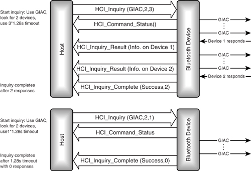
An inquiry will stop when Num_responses devices have responded to the inquiry, or when inquiry length time has passed, whichever happens first. Figure 8–11 shows the two ways in which an inquiry can successfully complete. In the top message sequence chart, an inquiry is started using the General Inquiry Access Code (GIAC), looking for a maximum of two devices and using a 3*1.28s timeout. The Bluetooth device transmits a stream of ID packets containing the GIAC. Two devices respond. Each response generates an HCI_Inquiry_Result, and after the second response, the HCI_Inquiry_Complete event is generated. In the lower message sequence chart, no responses are returned, so the inquiry times out, and the HCI_Inquiry_Complete event indicates that no responses have been received.
Figure 8–11 Message sequence charts for inquiries completing.
If the host decides to stop the inquiry early, it can do this with an HCI_Inquiry_Cancel command. Whether an inquiry completes on its own or is stopped because of an HCI_Inquiry_Cancel, an HCI_Inquiry_Complete event will be generated when it finishes. The HCI_Inquiry_Complete event contains a field giving the total number of devices which responded during the inquiry and a status field saying whether the inquiry completed successfully. The status field could contain an error code if the parameters used in the HCI_Inquiry request were invalid, if the module ran out of memory while collecting responses, or if there was a hardware failure during the inquiry.
8.5.4 Timing of Inquiries
Often, a host will want to keep inquiring for other Bluetooth devices in the area so that it is continuously updated with a picture of the Bluetooth neighbourhood. Continuously inquiring would drain batteries on a Bluetooth device, plus using the limited hop sequence of inquiry for long periods would violate radio regulations in some countries. The solution is to periodically perform short inquiries. The host could do this by periodically requesting the Bluetooth module to perform an inquiry, but the HCI offers an alternative where the Bluetooth module is put into a periodic inquiry mode. In this mode it will automatically perform inquiries. A host puts a Bluetooth module into the periodic inquiry mode using the HCI_Periodic_Inquiry_Mode command, and the mode is left using the HCI_Exit_Periodic_Inquiry_Mode command.
If inquiries were always performed at the same interval, it would be possible for an inquiring device and a scanning device to miss one another every time, so the periodic inquiry mode is not really periodic. Instead, inquiries are started at random intervals with the maximum and minimum intervals being specified in the HCI_Periodic_Inquiry_Mode command. These intervals are specified in multiples of 1.28 s. The HCI_Periodic_Inquiry_Mode command also includes all the parameters used in the HCI_Inquiry_Command: LAP, Inquiry_Length, and Num_Responses.
8.6 Inquiry Scan: Becoming Discoverable
A Bluetooth device allows other devices to discover it by conducting inquiry scans. (For more details on inquiry scanning, see Chapter 4.) A device which is conducting inquiry scans is said to be in discoverable mode. Devices in discoverable mode are able to respond to inquiring devices, thus allowing those devices to find out information about the discoverable device.
8.6.1 General and Limited Inquiry Access Codes
When a Bluetooth device conducts an inquiry, it sends out ID packets containing an Inquiry Access Code (IAC). Usually the General Inquiry Access Code (GIAC) will be used, but optionally a Limited Inquiry Access Code (LIAC) can be used for a short period of time. For instance, a group of users might agree to set their devices to use the LIAC to make their devices easier to discover in an environment with many Bluetooth devices.
An inquiry scanning device uses a correlator to listen for the Inquiry Access Code. Bluetooth devices can be built with multiple correlators so that they can scan for both Inquiry Access Codes simultaneously, although most devices will only have one correlator and will only be able to listen for one Inquiry Access Code at a time. A host can use the command HCI_Read_Number_Of_Supported_IAC to find out how many access codes a module can listen for simultaneously. Since version 1.0 of the Bluetooth standard only defines two possible Inquiry Access Codes, the number supported should be 1 or 2.
A host can find out which access codes a module is set to Inquiry Scan for using the command HCI_Read_Current_IAC_LAP. If the desired Inquiry Access Codes are not being used, the command HCI_Write_Current_IAC_LAP can be used to change Inquiry Access Codes.
8.6.2 Timing of Inquiry Scans
What’s the best strategy for a device wanting to be discovered by another? A device wanting to be discovered could conduct an inquiry scan until it has responded to an inquiry, then do a mandatory page scan. If that doesn’t result in a connection, it can go back into inquiry scan. At first thought, this seems like an excellent scheme; it means the device is spending as much time as possible in the inquiry scan state, so it’s maximising the chances of being discovered by an inquiring device, while dropping into page scan after responding to an inquiry still allows other devices to connect with it.
There are two problems with this idea of continuous inquiry scanning:
- Many Bluetooth devices will be battery-powered, and switching on the radio receiver uses far more power than leaving it idle, so continuous scanning could drain a device’s batteries.
- Some devices will want to conduct scans while connected so that they can connect to more devices. Continuous scanning would cause their existing connections to time out.
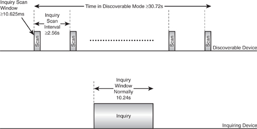
The solution is to scan in short bursts. The Generic Access Profile (GAP) recommends that a device should only scan for a 10.625 ms window. Of course, if a device is just scanning for a short period of time, it may miss an inquiry, so the Generic Access Profile recommends that inquiries last for 10.24 s, and devices in discoverable mode have a maximum interval of 2.56 s between starting one inquiry scan and starting the next. This means that while a device is conducting an inquiry, discoverable devices in the neighbourhood will conduct several inquiry scans, so they have a good chance of being discovered.
The host uses the command HCI_Write_Inquiry_Scan_Activity to set the interval between starting one scan and starting the next. The same command is also used to set the window of how long each scan lasts. If this command has never been sent to a device, the default interval between starting scans will be 1.28 s and the default window will be 11.25 ms. Naturally, the inquiry scan window must be less than or equal to the interval between starting inquiry scans. If the interval and window are set to be equal, the device will scan continuously. Normally, this would only be done for non-battery-powered devices that do not have any established connections. A host can use the HCI_Read_Inquiry_Scan_Activity command to check the settings of inquiry scan activity.
Even though a device is only scanning in short bursts, this would still cause extra drain on its batteries if it was idle or interfere with traffic if it was in connection. So, most devices will only scan occasionally. This means that it is important for scans to last long enough to give a good chance of being discovered by inquiring devices. The Generic Access Profile recommends that an inquiry last 10.24 s; it also recommends that devices remain discoverable for three times as long, at least 30.72 s. Inquiry scanning lasting three times as long as inquiry means that there is a good chance of inquiring devices in the area discovering inquiry scanning devices.
Figure 8–12 shows the timings the Generic Access Profile recommends for inquiry and inquiry scan. Although the figure is not drawn to scale, it still shows how during its time in discoverable mode, a device will repeatedly scan for short windows, whereas an inquiring device will occasionally conduct an inquiry over a relatively long window.
Figure 8–12 Recommended timings for inquiry and inquiry scan.
8.6.3 Enabling Inquiry Scan
Scanning is enabled using the HCI_Write_Scan_Enable command. The command HCI_Read_Scan_Enable may be used at any time to check whether scanning is enabled. This command returns the status of both inquiry scanning and page scanning.
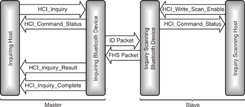
Figure 8–13 shows the message sequence chart for both inquiry and inquiry scan. When the inquiry scan has been enabled, the inquiry scanning module replies with HCI_Command_Status to confirm that it has received the command. After that, the inquiry scanning module can respond to any inquiries it sees, but it will not inform the host that it has responded. However, it may initiate a page scan after responding to an inquiry, and if that page scan results in it being paged, it will send an HCI_Connection_Request event to its host (for more details of how page scans may be conducted after inquiry responses, see section 8.8.2).
Figure 8–13 HCI message sequence chart for inquiry and inquiry scan.
8.7 Paging: Initiating Connections
A Bluetooth device connects to other devices by paging them, sending their Bluetooth address in an ID packet (for more details on paging, see Chapter 4).
The host uses an HCI_Create_Connection command to begin paging. This command contains all the information that the module needs to establish a connection. Its parameters are:
- BD_ADDR—The address of the device to connect with; this is sent in the paging ID packets.
- Packet_Type—The set of packet types which may be used on the connection (this sets the initial types, which can be changed later using HCI_Change_Connection_Packet_Type).
- Page_Scan_Repetition_Mode—This gives the interval between successive page scans starting, and hence governs how long it is likely to take to connect.
- Page_Scan_Mode—This specifies whether the device normally uses mandatory or optional page scanning mode (see section 8.8.2.1 for more details).
- Clock_Offset—The estimated offset of the paged device’s clock relative to the local clock.n
- Allow_Role_Switch—This tells the device whether to accept a Master/Slave switch during establishment of a connection (see Chapter 7 for more details on Master/Slave switch).
If the device being paged recently replied to an inquiry scan, then Page_Scan_Mode, Page_Scan_Repetition_Mode, and Clock_Offset information will have been returned in the FHS packet used for the inquiry response. However, it is possible to connect to a device just by entering its Bluetooth device address at the user interface. In this case, these three items of information may be missing. It would be possible to require the user to enter the information, or to conduct an inquiry to discover the extra information, but either option would slow down the process of connecting. It makes more sense to just set unknown parameters to default values. The Bluetooth standard does not specify defaults, but looking at what each parameter does, it is possible to work out some values which could be used:
- Page_Scan_Repetition_Mode—This parameter governs the time between successive page scans starting. It is best to assume the worst case: mode R2, time between successive page scans starting at 2.56 s.
- Page_Scan_Mode—Begin by assuming the device uses mandatory scanning; most devices will use this. If no connection is established, try again with this parameter set to optional page scanning.
- Clock_Offset—If the device was not found in a recent inquiry, this information is irrelevant, and the value may as well be set to zero.
Paging is started with an HCI_Create_Connection; it either finishes when a connection is established or when a Page Timeout elapses. The timeout value can be set using the HCI_Write_Page_Timeout command, and checked with the HCI_Read_Page_Timeout command.
An HCI_read_clock_offset command allows the host to read the clock offset between the remote device on a connection handle and the local clock. The result is received in an HCI_read_clock_offset_complete_event. The clock offset decides the phase in the page scan sequence on which a device is listening at any moment, so if the information could be passed to another device, it could be used to facilitate handover of Bluetooth Slaves from one Master to another. Of course, the hosts handing over would need some data link to exchange the slot offset information—for instance, LAN access points could ecxhange the information across the LAN backbone.
8.8 Page Scan: Receiving Connections
A Bluetooth device allows other devices to connect to it by entering page scan mode (for more details on page scanning, see Chapter 4). A device which is page scanning listens for its own ID in packets sent from a paging device. If it sees its own ID, it will respond and the two devices set up a new connection.
8.8.1 Timing of Page Scans
Section 8.6.2 dealt with inquiry scans and explained that continuous inquiry scanning would waste power and bandwidth. The same arguments apply to page scanning, so page scans are conducted in short bursts, and commands are provided to set the timing parameters of the page scanning bursts.
HCI_Write_Page_Scan_Activity sets the interval between the start of successive page scans and the length of the window over which a device page scans. This command is very similar to the command HCI_Write_Inquiry_Scan_Activity described in Section 8.6.2. To check the value of the page scan activity parameters, the host can use the HCI_Read_Page_Scan_Activity command at any time.
Changing the page scan interval could change the page Scan Repetition mode. The page Scan Repetition mode (SR) is a rough measure of the interval between consecutive page scans (Tpage scan). There are three modes defined: R0 continous scanning, R1 Tpage scan ≤ 1.28s, and R2 Tpage scan ≤ 2.56s.
If a module notices that the page scan repetition mode of a remote device has changed, it notifies its host using an HCI_Page_Scan_Repetition_Mode event. Since the page SR mode is only passed between devices in the SR field of an FHS packet, only an inquiring module would notice the change in the scan repetition mode. The module could simply send an HCI_Inquiry_Result event with the new page scan repetition mode in it, but it might be configured so that it cannot send multiple HCI_Inquiry_Result events for the same device, making this an impractical solution. The HCI_Page_Scan_Repetition_Mode event allows the Bluetooth module to let the host know of the change without needing another HCI_Inquiry_Result event.
8.8.2 Enabling Page Scan
Page scanning is enabled using the same command used to enable inquiry scanning, the HCI_Write_Scan_Enable command.
One odd feature of the scan settings is that if HCI_Write_Scan_Enable is set so that inquiry scanning is enabled but page scanning is disabled, after responding to an inquiry, a Bluetooth device can still enter a page scan. At first thought, this may seem nonsensical. Why conduct a page scan if page scanning has been disabled? On the other hand, consider: What’s the point of responding to an inquiry and announcing your presence if you won’t let other devices connect to you? Sensibly, the writers of the Bluetooth specification reasoned that nobody would want to respond to inquiries but not allow devices to connect. They could have just not allowed Bluetooth devices to have inquiry scanning enabled when page scanning was disabled, but instead they provided a special mechanism to allow Bluetooth devices to save battery power by having devices with these settings only page scanning just after they responded to an inquiry. This way, they can receive connections, but they don’t waste battery power or bandwidth by doing page scans when there are no other devices in the area that know their address.
Table 8–1 summarises the behaviour of a device according to its scan settings.
Table 8–1 Scan Settings

The HCI_Read_Scan_Enable command may be used at any time to check whether scanning is enabled. This command returns the status of both inquiry scanning and page scanning.
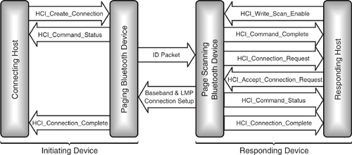
8.8.2.1 Accepting a Connection. If a page scan is successful, eventually an ID packet will be received with the page scanning device’s Bluetooth device address in it. It is possible that the module has been set to automatically accept connections using the HCI_Set_Event_Filter command. In this case, the host would not know the connection was there until it was completely set up. However, if the host has not set the module to automatically accept connections, the module will announce to its host that it has been paged by sending the host an HCI_Connection_Request event. The host will reply with an HCI_Accept_Connection_Request or HCI_Reject_Connection_Request.
If the host does not reply for some reason, then the connection needs to be rejected. How long is it reasonable to wait for the host’s reply? There is no absolute answer, as some systems ought to respond faster than others. For example, if the host is a PC which may have to be booted before it can decide whether to accept the connection, then a very long timeout is needed. If the host is always on, then a faster timeout would be appropriate. To cope with the different timeouts which different hosts require, Bluetooth’s HCI standard provides an HCI_Write_Connection_Accept_Timeout command. This allows the host to set the time a module will wait for the response to the HCI_Connection_Request message. The timeout’s default value is 5 s, but it may be set to values between 0.625 ms and 29 s. The timeout is set in multiples of 0.625 ms (the time for one baseband slot). If the host has not responded when the timeout elapses, then the connection is rejected as if the host had sent an HCI_Reject_Connection_Request command. A host may use the HCI_Read_Connection_Accept_Timeout command at any time to check the current value of a module’s Connection_Accept timeout.
If the connection is accepted by the host, then the baseband and LMP layers finish setting up the connection. Once this is done, the hosts on both sides are notified by their modules sending them an HCI_Connection_Complete event, which contains the connection_handle that is used to uniquely identify the connection. The sequence of HCI commands leading up to the connection being completed is shown in Figure 8–14.
Figure 8–14 HCI message sequence chart for creating a connection.
Once the connection is finished, the host can use an HCI_Disconnect command to terminate the connection. The link to disconnect is specified using the connection handle that was passed to the host in the HCI_Connection_Complete event. A reason code is used to indicate why the disconnect is sent; for example, possible values include Authentication Failure error code, Other End Terminated Connection error codes, and Unsupported Remote Feature error code.
8.8.3 SCO Connections
Once an active ACL connection has been set up, a SCO connection can be set up across it using the HCI_Add_SCO_Connection command. The parameters for this command specify the connection handle of the ACL connection across which the SCO connection will be set up, as well as the packet type to be used on the SCO connection. This must be one of the SCO packet types: HV1, HV2, or HV3.
As for creating a SCO connection, an HCI_Command_Status event is returned immediately to acknowledge the command. When the connection has been established, an HCI_Connection_Complete event is returned with the connection handle for the SCO connection (if the connection fails, the HCI_Connection_Complete event will still be returned, but its status field will carry the reason for failure).
8.8.4 Optional Page Scan Modes
In normal Bluetooth operation, the Master transmits in even slots and the Slaves reply in odd slots. This applies to Bluetooth’s mandatory paging mode. Bluetooth also has an optional paging mode in which the Master transmits ID packets for eight slots; in the ninth slot, an inverted ID packet is sent, and the tenth slot is free for the Slave to reply (for more details see section 5.4.3).
The page scan mode can be changed with an HCI_Write_Page_Scan_Mode command. When the mode changes, an HCI_Page_Scan_Mode_Change Event is generated by the module and sent to the host. If the host wants to check the current page scan mode, it uses an HCI_Read_Page_Scan_Mode command. It is possible for a module to use more than one mode at once, in which case, all modes supported are returned in the HCI_Command_Complete event, which is used to respond to the HCI_Read_Page_Scan_Mode command.
Because the optional page scan modes are not supported by all devices, it is possible for an inquiring device which doesn’t support optional page scanning to get a response from a device which is using optional page scanning. To give the inquiring device a chance to connect to the devices it discovers, all devices use the mandatory page scan mode for a short time after each inquiry response.
Every time an inquiry response is sent, the Bluetooth device starts a timer, T_mandatory_pscan. Until this timer expires, the mandatory page scanning scheme is used for all page scans.
The page scan period mode decides how long the T_mandatory_pscan timer will be. There are three possible modes:
- P0, Tmandatory pscan > = 20s.
- P1, Tmandatory pscan > = 40s.
- P2, Tmandatory pscan > = 60s.
The inquiring device can tell how long it has to page a device it discovered because the page Scan Period (SP) mode is passed in the inquiry response in the SP field of the FHS packet.
To change the page scan period mode (SP), the host simply sends a new mode using an HCI_Write_Page_Scan_Period_Mode command. To check the value, the host sends an HCI_Read_Page_Scan_Period_Mode.
8.9 Sending And Receiving Data
When a connection is set up across HCI, a connection handle is returned to the host in the Connection_Complete event. When the host sends and receives data, this handle is used in the HCI_ACL_data packet to identify the connection (see Figure 8–4 for details of the packet structure).
Figure 8–15 shows how data is exchanged. The HCI_ACL_Data packet containing the data is sent from the transmitting host to the Bluetooth module. The data from the packet is transmitted across an ACL link in a series of baseband packets. At the far end of the link, the data is passed to the receiving host in one or more HCI_ACL_Data packets. The diagram shows data passing in one direction only, but, of course, ACL links are bidirectional, so data can pass in both directions.
Figure 8–15 HCI message sequence chart for ACL data exchange.
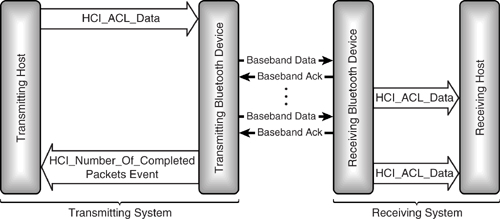
It is possible that the size of the payload carried in HCI_ACL_Data packets at each end of the link may be different, or the receiving module may even decide to generate one HCI_ACL_Data packet for each baseband packet it receives; as long as the order of the data is preserved, this does not matter.
8.9.1 Broadcasting Data
Systems which use connection handles usually reserve a special handle to identify a broadcast. Bluetooth does not have a reserved handle for broadcast; instead, the first time the host wants to broadcast data, it uses a handle which has not been used for a connection. When the Bluetooth module receives a packet with a connection handle which has not yet been allocated, it is allocated as the new handle for the broadcast channel.
Having the Bluetooth module allocate all point to point handles but letting the Blue-tooth host allocate the broadcast handle complicates the implementation of HCI on the Bluetooth module. Usually, handles have some internal significance to the module; for instance, they may contain pointers to data structures holding channel parameters. This may mean that the Bluetooth module has to translate the host’s broadcast handle to its own internal broadcast handle. If letting the host allocate broadcast handles causes such trouble for the Bluetooth module, why did Bluetooth implement broadcast handles this way? In version 1.0 of the specification, no handle was reserved for broadcast, and the specification writers had agreed not to add assigned numbers to the lower layers of the protocol stack, so having broadcast handles chosen at run time avoids an extra assigned number.
One complication of the host allocating the broadcast handle is that data sent on a new broadcast channel could overlap with an HCI_Connection_Complete event which uses the same handle. The host handles this as follows:
- Stops sending broadcast packets using the conflicting broadcast handle.
- Waits for an HCI_Number_Of_Completed_Packets event, indicating all broadcast packets sent on the conflicting handle have been sent.
- Allocates a new broadcast channel handle which doesn’t conflict with point to point handles.
8.10 Switching Roles
During initial configuration of a connection, or at any time while it is in active use, devices can request to switch Master and Slave roles. A host can force this to happen with an HCI_Switch_Role command. The parameters for this command are the Bluetooth device address of the device with which the role switch is to be performed and the role which the host wants to have on the link. If the command is successful and a role change takes place, an HCI_Role_Change event will be sent to the host (this is sent instead of the HCI_Command_Complete event, which is usually sent to the host when a command finishes). The same HCI_Role_Change event is sent if a role change occurred which was initiated at the remote end of the link.
It is possible that a host may lose track of whether it is currently a Master or a Slave on a link. In this case, it may send an HCI_Role_Discovery command to its module. As a Bluetooth device can be a Master on some links and a Slave on others, this command takes a connection handle to identify the link for which the role is to be discovered.
The HCI_Write_Link_Policy_Settings command can be used to disable role switching on any link. The current policy settings for any link can be checked at any time using the HCI_Read_Link_Policy_Settings command.
8.11 Power Control
In Chapter 1, we saw how LMP could be used to control end-to-end power on a Bluetooth link. Power control uses the Receive Signal Strength Indication (RSSI), and the host can read this value using the HCI_Read_RSSI command. Since a Bluetooth device may be connected to several other devices simultaneously, and these devices may be different distances away and have different receiver qualities, the RSSI may be different on each link. Therefore, the HCI_Read_RSSI command takes as a parameter a connection handle to identify which link’s RSSI is being read.
Transmit power as well as receive strength can be read. The HCI_Read_Transmit_Power_Level command takes a connection handle parameter to specify which link’s transmit power level is being read. This command can be used to read both the current transmit power level and the maximum power level the module can transmit. A type parameter is used to identify which is being requested. Power levels are returned in an HCI_Command_Complete event in units of dBm.
8.12 Summary
A Bluetooth device can be made up of two parts: a host implementing the higher layers of the stack (L2CAP and above) and a module implementing the lower layers (LMP and below). The Host Controller Interface (HCI) provides a uniform interface between a Blue-tooth host and its module. Because the HCI is standardised, host software can interwork with Bluetooth devices from a variety of manufacturers.
The HCI uses three packet types: commands which go from host to module, events which go from module to host, and data packets which travel in both directions. Between them, these three packet types can be used to completely control a Bluetooth module and to transfer any data required.
HCI commands allow the host to completely control a Bluetooth module, including:
- Control of links, including setting up, tearing down, and configuring links.
- Setting the link policies on whether power saving modes and role switches are allowed.
- Direct access to information on the local Bluetooth module and access to information on remote devices by triggering LMP exchanges.
- Control of many baseband features such as timeouts.
- Retrieving status information on a module.
- Invoking Bluetooth’s test modes for factory testing, and for Bluetooth qualification.
The HCI includes flow control capabilities, so implementers may wish to use an alternative route to get SCO data into the baseband; otherwise, the flow control may interfere with the regular synchronous transfer of voice samples to and from the Bluetooth module.