
5
The Link Controller
5.1 Introduction
This chapter continues on from where the baseband chapter left off, looking at how the link control layer configures and controls the link and packet-oriented baseband. The link control layer carries out higher level operations such as inquiry and paging and manages multiple links with different devices and even different piconets.
5.2 Link Control Protocol
The link control protocol is carried in the LC Channel as defined in the previous chapter, and is responsible for the mechanics of maintaining a link once it has been set up. Before moving onto looking at the overall link control state machine, we will first consider the Acknowledgement/Request (ARQ) scheme used for retransmission of corrupted data, as this forms a key part of the overall picture.
In every packet header, the ARQN flag will indicate the status of the previously received packet. ARQN = 1 (ACK) means the packet has been received and correctly decoded. ARQN = 0 (NAK) means that the previous receive failed.
A NAK occurs under the following conditions:
- A Slave fails to detect an access code and no receive occurs—Although mentioned in the specification, this is not actually possible as a Slave may only respond when it knows it has been transmitted to.
- A Master fails to detect an access code and no receive occurs—The Slave’s response to a Master transmission has been lost.
- An access code is detected and the HEC fails—If the HEC has failed, we do not know who the packet was addressed to. In a piconet, all Slaves will potentially respond with NAK, except they are not allowed to respond unless they successfully decode and match the AM_ADDR. As for the first point, this is also not possible.
- An access code is detected and the CRC fails—This is the usual reason for a retransmit condition during connection.
Each time a new packet with a CRC is transmitted, the SEQN flag is toggled, whereas for a retransmitted packet, the SEQN flag will remain the same as the previous value. This allows a receiver to tell the difference between a packet which has been retransmitted because the receiver NAK’d the previous packet and a packet which has been retransmitted because the transmitter failed to receive the receiver’s ACK flag correctly. In essence, if a packet is received correctly, but the SEQN flag is the same as the previously received SEQN flag on that link, then the packet is ignored. However, an ACK is returned subsequently so that the remote device will eventually stop retransmitting.
The Link Manager (LM) may request the Link Controller (LC) to flush its transmit buffer. Typically, this will occur after a timeout following a repeated retransmission attempt. If the payload is flushed, the SEQN flag will be unaffected, since an ACK is still required. If the ACK arrives just prior to transmission of the new packet following the flush, then the SEQN flag will be toggled in the normal way. Otherwise, the SEQN will remain as before and we will now be awaiting an ACK for what is now a new payload. This facilitates the transmission of isochronous data (see the section on logical channels).
In certain circumstances, the ARQN / SEQN state on receive and transmit is maintained as unaffected across several slots and executed much later. Packets where the access code and HEC check out, but the AM_ADDR is not that of the recipient or reception of any packet other than a Dx (DH, DM, or DV), do not affect the ARQN and SEQN flags. They are also unaffected during Hold or Sniff modes.
The ARQN and SEQN flags are initialised by the first packet exchange following setup of a link. The initial ARQN = NAK from both Slave and Master and both SEQNs are initialised to 1.
5.2.1 Broadcast
A Master may send data to all Slaves participating in the piconet simultaneously. The Master does this by sending any packet where the AM_ADDR field is set to zero (the broadcast address). All Slaves that successfully decode this “broadcast” packet will act on it. Since the broadcast is directed at more than one device, the ARQ scheme described above is not applicable.
The alternative used is to always retransmit broadcasts a specified number of times. The ARQN flag is unused; however, the SEQN flag is used to identify the retransmitted packets. A broadcast message lasting several packets is segmented into a number of Blue-tooth packets, where each is retransmitted “NBC” times in succession.
Broadcast L2CAP packets will be fragmented into multiple baseband packets, with each one transmitted NBC times. Each new broadcast packet in a sequence is identified by toggling SEQN. However, the specification specifies that the sequence is reset to 1 at the start of each broadcast L2CAP or LMP packet. LMP packets fit into a single baseband packet, so if a series of LMP messages are sent, the SEQN flag will remain at 1. So there is no way of filtering out repeat LMP transmissions. Similarly, if an L2CAP packet is segmented into an odd number of baseband packets, the SEQN flag will be set to 1 for the transmissions of the end fragment of the L2CAP packet and will be forced to remain at 1 for the start of the next L2CAP packet. So the SEQN bit cannot be used to distinguish between the final fragment of the first packet and the start of the next packet. L2CAP cannot filter these packets either, and so they will be sent further up the stack, causing higher layers to receive multiple packet fragments. Indeed, the L2CAP part of the specification specifies that the use of baseband broadcast packets is prohibited if reliability is required. A somewhat telling statement!
A simple way to remedy the situation would be to make broadcast sequencing behave the same way as for any other packet. The SEQN sequence would continue from one sequence of broadcast packets to the next, instead of being reset to 1 at every LMP or L2CAP start packet. For single packet messages, SEQN would toggle on each one and any successive identical values would truly identify a retransmission, with the receive being aborted in the usual way.
This would require a change to the specification and many existing Bluetooth products. Therefore, it is unlikely to occur for the existing 1.1 specification. However, this is one of a number of issues that are worthy of consideration as the specification evolves past 1.1.
5.3 Link Controller States
At any one time, a Bluetooth device is in one of a number of different states. The “major” link control states are first defined below, before a detailed examination of how a device moves from one state to another and carries out higher level operations such as connection establishment under the control of the application via the stack and LM.
5.3.1 Standby
In the standby state, the device is inactive, no data is being transferred, and the radio is not switched on. Thus, the device is unable to detect any access codes. This state is used normally to enable low power operation.
5.3.2 Inquiry
Inquiry is the process whereby a device will attempt to discover all the Bluetooth enabled devices in its local area. The baseband end of the Service Discovery Protocol (SDP), it allows a device to compile a list of devices which it may wish to connect with at a later time. During the inquiry procedure, the inquired upon devices will supply FHS packets to the inquirer. The FHS packets allow the inquirer to build a table of the essential information required to make a connection, such as CLKN, which controls the on-air timing, and frequency hop sequence, BD_ADDR, which controls the frequency hop sequence and forms part of the access code, and the BCH parity word, which also forms part of the access code.
5.3.3 Inquiry Scan
Inquiry scan is the other half of the inquiry procedure. Although scanning is optional and up to the application, most devices will periodically enter inquiry scan state to make themselves available to inquiring devices. They listen for an extended time (this is necessary, as they have no knowledge of the timing or frequency hop behaviour of any inquiring devices) for the inquiry packet using the fixed General or Dedicated Inquiry Access Codes (GIAC, DIAC). When they receive a valid inquiry message, they enter the inquiry response substate and respond with the FHS information as described above. The inquiry and inquiry scan states utilise a special hopping sequence (fast for inquiry and slow for inquiry scan), which is designed to reduce the amount of time before a frequency match occurs.
5.3.4 Page
To establish a connection, the device which is to become Master is instructed by the application to carry out the paging procedure. The Master first enters the page state, where it will transmit paging messages directed at the intended “Slave” device (using the access code and timing information gained from the previous inquiry procedure). The Slave acknowledges the paging message and the Master enters the master response substate and responds with its FHS packet.
5.3.5 Page Scan
As for inquiry scan, a device will typically enter page scan periodically to allow paging devices to establish a connection with it. Once a device in page scan state has successfully received a paging packet, it will enter the Slave response substate where it acknowledges the packet and awaits the FHS. On reception of the FHS, it updates its own CLK timing and sync word / access code reference before entering the connection state. Again, like the inquiry procedure, the paging procedure uses a special hopping sequence (fast for page and slow for page scan), which is designed to reduce the amount of time before a frequency match occurs.
It is possible to carry out the paging procedure with no prior inquiry if the device address is already known, as may be the case with a dedicated laptop/cellular phone arrangement, for example. The paging device is able to address the intended Slave, but because no CLKE (estimate of the Slave’s clock) is available, the procedure will take much longer. In theory, the maximum length of time is 10s.
5.3.6 Connection – Active
On entry to the connection state, the Slave switches to the Master’s CLK (by applying the relevant offset to its own CLKN) and thus moves on to the Master’s frequency hop and timing sequence. The Master transmits a POLL packet to verify that the link has been successfully set up. The Slave must then respond with any type of packet, typically a NULL. Both ARQN flags are set for NAK, but the next transmission by the Master will start the ARQ, SEQ sequencing for real. If the connection fails to establish in this way, then after suitable timeouts, both devices revert to page and page scan, respectively and the whole process may restart.
Although a Slave may not actually be addressed for many slots, it stays synchronised to the Master during a connection by correlating against the Master’s access code—referred to as the Channel Access Code (CAC)—in each packet the Master transmits, even if it is not destined for that Slave. The Master must therefore keep transmitting periodically, even if there is no data to send. It will use NULL packets for this purpose if necessary.
Once a Slave has triggered on the CAC and received the packet header, it will often find that the AM address does not match its own and must then abort the remainder of the reception. Since the packet type field in the header will tell it how many slots the packet will last for, it may use this information to enter Low Power Sleep mode for the duration of the Master’s transmission.
During connection state, various data exchanges and logical channels are possible. However, from time to time, any device in connection state may move into a low power substate as described below.
5.3.7 Connection – Hold
In Hold mode, a device ceases to support ACL traffic for a defined period of time to free up bandwidth for other operations such as scanning, paging, inquiry, or Low Power Sleep. The device does, however, maintain its AM address. After the hold time has expired, the device synchronises to the CAC and begins to listen for traffic again.
5.3.8 Connection – Sniff
In Sniff mode, a Slave device is given a predefined slot time and periodicity to listen for traffic. The Slave will listen at slot number Dsniff every Tsniff slots for a timeout period of Nsniff slots. On reception of a packet during this time, it will continue to listen until packets with its AM address stop and the timeout period ceases. It then waits for the next sniff period.
5.3.9 Connection – Park
In Park mode, a Slave gives up its AM address and listens for traffic only occasionally. For the most part, the device is able to enter Low Power Sleep mode. The device only needs to wake up at a defined “Beacon” instant to synchronise to the CAC before returning to low power mode again. In this way, the Slave is able to stay synchronised to the Master even though it is running from a far less accurate Low Power Oscillator (LPO).
5.4 Link Controller Operation
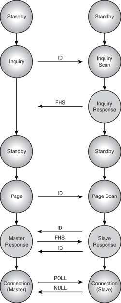
The familiar Bluetooth device state diagram appears in Figure 5–1. This diagram apparently shows routes going from standby, through inquiry, to connection. In fact, there is no such direct route. To establish a connection, one must go through paging or page scanning. The diagram is intended to show that the inquiry state can be entered either from standby or from connection. It does not show the routes through the states to establish connections.
Figure 5–1 Link controller state diagram.

A simpler view of the major routes through the state diagram is illustrated in Figure 5–2. This gives a clear and simple picture of how a single link is established from scratch. However, in practice, the state transitions can be much more complex. For example, a Master in connection state already occupied with regular SCO traffic may carry out periodic inquiry operations to look for new would-be Slaves, paging operations to add new Slaves to the piconet, and even inquiry or page scans in case other would-be Masters are looking to add it as a switched Master / Slave to their piconets to create a scatternet!
In fact, a device in a fully active scatternet situation may switch from almost any of the major states to another as it moves between connection, link setup, inquiry, and power-saving operations. It is very important to realise that the apparently simple state machine shown in Figure 5–1 effectively represents only the state of one link between two devices at any one time. As another link is established, another instantiation of the state machine is made. Thus, a Master may be in connection with one Slave while simultaneously inquiring, paging, and scanning several other devices. Indeed, since inquiry or paging may last several seconds, the Master will effectively be moving directly from connection to inquiry, to scan, to page, and back to connection as it works around the set of devices it is interacting with. In essence, the one state controller entity requires a set of contexts for each of its active interactions or links. This is also true for the LC protocol, ARQN, SEQN, and retransmit packets. Early Bluetooth implementations placed much of this control in hardware and found this to be a very difficult juggling act. One of the key challenges for Bluetooth designers is getting the partitioning between hardware and software right. This area of state control and link context management is at the sharp end of the partitioning problem. We examine this in more detail in the implementation chapter.
The diagram in Figure 5–2 illustrates the state transitions and packet exchanges which occur while a pair of devices moves from standby into connection through a simplified view of the inquiry and paging procedures. We now look in more detail at the exact message exchange sequence and timing related to inquiry and paging.
Figure 5–2 State transition from standby into connection.
5.4.1 Device Discovery and Inquiry
Due to the ad-hoc nature of a Bluetooth network, where highly mobile devices may come into and go out of range of other communicating devices, the network topology and membership can be constantly changing. The Bluetooth specification provides a mechanism for device discovery, which is what the Service Discovery Protocol (SDP) is built upon. The LC uses inquiry and inquiry scan states to manage the process of device discovery in the devices wishing to discover and be discovered, respectively.
Figure 5–3 shows the messages exchanged between two devices during inquiry and inquiry scan. The inquiring device is asking “Is anybody out there?” while the scanning device is constantly listening in case anybody inquires.
Figure 5–3 Message sequence chart for inquiry and inquiry scan.
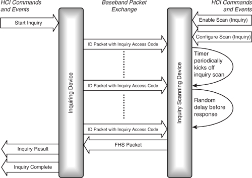
The inquiring device calls out by transmitting ID packets containing an Inquiry Access Code (IAC) as described in the section on access codes in the baseband chapter. Usually, the General Inquiry Access Code (GIAC) is used, which is common between all
devices performing inquiry procedures. However, devices can use a Dedicated Inquiry Access Code (DIAC). The concept of a Dedicated Inquiry Access Code was originally provided to allow only certain classes of devices to be enquired upon, but the only DIAC defined to date is the Limited Inquiry Access Code (LIAC). The LIAC is designed to be used by a pair of devices for a short period of time. This would be by Application Level selection on both devices and provide a quick way of discovering a “known” device.
To conserve power and fit in with other link activity in which a device may be engaged, inquiry will only happen if specifically requested by the higher layer control protocols. Likewise, the device will normally be set to only perform inquiry scan periodically over a short window. The chapter on the host controller interface gives more detail on how this is done.
When an inquiry scanning device hears an inquiry, it could respond immediately, but this could result in several scanning devices responding together the moment an inquiry was sent. The responses would interfere with one another, so the inquirer would not receive any of them. To stop this from happening, a random back-off period is used. When a scanning device first hears an inquiry, instead of responding immediately, it waits for a random period, and then re-enters the scanning state, listening once more for another ID. This time, if it hears the inquiry, it will reply with the FHS packet. In this way, several devices can respond to an inquirer, but their responses will be spaced out randomly and will not interfere. Clearly, the inquirer must keep inquiring for longer than the range of the random period.
Figure 5–4 shows in detail how an inquiring device transmits twice per slot on successive hop channels (fast hopping), trying to “catch” a device performing inquiry scan which hops at the scan rate of only once every 2,048 slots, or 1.28s. The inquirer transmits using the inquiry hop sequence and listens in both halves of the slot on the associated response hop sequence. See the section on frequency hopping in Chapter 4, “Baseband.”
Figure 5–4 Inquiry procedure timing.
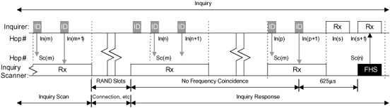
Once the inquiry scanning device successfully receives an ID packet, it waits for the random back-off period (RAND), between 0 and 1,023 slots, or up to 640 ms to avoid collisions. After the RAND period, the inquiry scanning device enters inquiry response and on the next reception of an ID packet, responds with the FHS packet 625 μs later, providing the inquirer with the required information. Both devices hop between two different points in the sequence depending on their own values of CLKN(1), which is 0 for the inquiry device on transmit and the scanning device on receive. Thus Sc(m) = In(p+1) in Figure 5–4. The response is then made in the next slot where CLKN(1) is 1, and so Sc(n) = In(s + 1), where m and n and p and s differ only by the effect of the respective CLKN(1). The scanning device then re-enters inquiry scan state on the next channel in the inquiry scan hop sequence and waits for another ID packet.
Because the inquirer always listens on the response hop channel corresponding to the previous inquiry transmission, when the inquiry scanning device returns an FHS packet, it is ready to receive it. However, because there is no defined relationship between the two CLKNs, this is not an exact process and that is why repeat attempts are made. The inquiry procedure timing is as it is exactly to maximise the “chance” of coinciding.
If the inquirer receives the FHS packet in the first half of its receive slot, it cannot receive a response from another Slave in the second half of the slot because it does not have time to hop to the second frequency after receiving the FHS packet. Similarly, if the FHS packet comes in the second half of the receive slot, the inquiring device will miss the transmission of the first ID packet in the following transmit slot (this is shown in Figure 5–5).
Figure 5–5 Hopping during inquiry response.

As the inquiring device hops twice per slot while the inquiry scanning device listens on a single frequency, the time taken for an inquiry to be received is reduced to half the time which would be taken if the inquiring device hopped at the normal rate of once per slot. Such rapid frequency hopping is only possible because ID packets are very short.
If the inquiry scanning device does not receive the first or second ID packets during the scan timeout period, then it will leave inquiry scan and return to standby or connection as appropriate. The inquiry state lasts either as long as required to collate the desired number of responses, or until a timeout set by the host elapses. In an error-free environment, the worst case is around 10 s to guarantee frequency coincidence with all devices in the inquiry hop sequence. If the inquiring device has active SCO links, then the period must increase to take account of the lost time due to the regular SCO activity. See the section on SCO links.
It is permissible to avoid Inquiry altogether if the address of the device to connect to is known. Paging may be entered directly, although it may take longer to establish a link, as without the CLKE estimate, the paging hop sequence is not predictable. This may be appropriate, for example, where a very low cost mobile phone and headset combination had a minimal Man Machine Interface (MMI) and their respective addresses were factory preset to tie them together.
5.4.2 Connection Establishment and Paging
We have already seen in the previous chapter that the Bluetooth system is based around the notion of links between a Master device and a Slave device. To establish such a link, one device must initiate the connection by addressing a request directly to the other device saying: “Will you connect with me?” This is referred to as paging. The other device must likewise be listening for such a request, and this is referred to as page scanning. At the conclusion of the paging process, the pager becomes the Master and the page scanner becomes the Slave, though this may subsequently change due to a Master / Slave switch.
Figure 5–6 Message sequence chart for paging and page scanning.
must likewise be listening for such a request, and this is referred to as page scanning. At the conclusion of the paging process, the pager becomes the Master and the page scanner becomes the Slave, though this may subsequently change due to a Master / Slave switch.
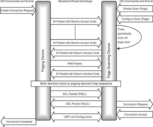
Figure 5–6 shows the messages exchanged between two devices during the connection establishment process using the mandatory paging procedure. One optional paging procedure is defined, although others may be added in the future. We describe the mandatory scheme in detail here, but look briefly at the optional scheme later.
Figure 5–7 Page procedure timing.
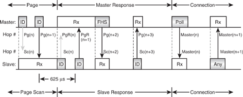
The create connection command causes a device to enter paging mode, where it sends out a series of paging packets (ID packets based on the paged device’s address). Meanwhile, the page scanning device is configured to carry out periodic page scans of a specified duration, and at a specified interval. The scanning device starts a timer and kicks off a periodic scan when the timer elapses. (This is the same mechanism used to configure periodic inquiry scans and is also described in Chapter 8 on the Host Controller Interface.) The pager transmits ID packets with the page scanner’s address. If the page scanner is scanning during this time, it will trigger and receive the ID packet, replying with another ID, again using its own address. Unlike inquiry, there is only one device with that ID, so only one device can reply and there is no need for any random back-off delay. The pager receives the page scanner’s ID packet and, following this handshake, knows that the page scanner is ready to receive the pager’s FHS packet, which it then transmits. The page scanner acknowledges the FHS packet by replying with another ID. Now the page scanner can extract the necessary parameters from the FHS packet (Bluetooth CLK, AM_ADDR, etc.) to use in the new connection. Using these parameters, the page scanner is able to calculate the pager’s hop sequence. It can stop using the special paging hop sequence and move instead to the connection hop sequence with the pager as Master of the connection. As both devices now move into the connection state, the pager becomes the Master and the page scanner becomes the Slave.
After both devices have moved to the new hop sequence, the Master sends a POLL packet to check that the frequency hop sequence switch has happened correctly. The Slave must then respond with any ACL packet (typically a NULL, as there is unlikely to be any data to send at that specific time). Following this link test and first ACL packet exchange, various LMP link configuration packets are exchanged. At this point, Master and Slave can agree to swap roles in a “Master/Slave switch” if required.
Figure 5–7 shows in detail the packet exchange and timing between a pager and page scanner during the mandatory paging procedure.
The Master1 transmits IDs on a sequence of hop channels which straddle the predicted channel of the Slave1 based on the estimate (CLKE) of the Slave’s CLKN at a fast rate, twice per slot. This is necessary, as CLKE may be inaccurate or even nonexistent where an inquiry has not previously been carried out. The 32 channel hop sequence is split into 16 surrounding the predicted channel and a further 16 split either side of these. The inner set, or “Train A,” is tried first, and then the more distant set, “Train B”. This aims to give the fastest response possible if an accurate CLKE is available, while guaranteeing success eventually in the worst case scenario. As with inquiry, the paging device hops twice per slot to maximise the chance of hitting the page scanner’s frequency. The scanner hops over the same channels, but at a rate of only once per 2,048 slots, or 1.28s. This ensures that they will eventually coincide, providing the respective timeout periods are sufficient.
1We have adopted the terms “Master” and “Slave” here in place of “pager” and “page scanner,” since as the Bluetooth specification describes paging procedures in terms of Master and Slave. Thus, the response substates are Master response and Slave response. This is a little confusing, however, as a Master in an existing piconet might be the page scanner in another new piconet.
In the diagram, “Pg” refers to the page hop channels and “Sc” to the page scan hop channels. “PgR” indicates the page hop channel, which is used for the Master response and is linked to the page hop channel during which the ID was successfully received by the Slave. Once the scanning device has received the ID packet, it freezes the hop clock and starts to hop in sequence with the paging device. It does this using the page response hop sequence discussed in the previous chapter.
When the Master receives the ID, it transmits the FHS packet at the beginning of its next slot, to allow the Slave to synchronise its slot reference. The Slave must therefore open its correlator 312.5 μs after the ID is sent and keep it open for at least 625 μs, as the FHS could be due in either 312.5, or 625 μs time. Following reception of the FHS packet, the Slave responds with an ID. Up to this point, both devices are using the Slave’s DAC, the Slave’s timing (Slave: CLKN, Master: CLKE), and a paging hop sequence derived from the Slave’s LAP. The next transmission is from the Master using the CAC and its own CLKN, which the Slave receives as it has now switched to the Master’s CAC and CLK and both devices are in connection state. The devices now exchange POLL and NULL packets to verify the link. If the POLL packet is not received or acknowledged within a timeout period, then both devices will return to page and page scan states, respectively.
5.4.3 Optional Paging Scheme
In version 1.0b of the Bluetooth specification, one optional paging scheme was defined; others may be added to later versions of the specification. The current optional scheme operates as follows: The paging device transmits for eight slots in both odd and even slots, then inverts the ID packet and transmits again. In the tenth slot, it listens for the Slave’s response. Whereas the normal ID packets will generate a positive signal from the scanning device’s correlator, the inverted packet will generate a negative signal. By checking the sign of the correlator’s output signal, the scanning device can detect when the ID packet is inverted and work out when to send its response.
By transmitting for nine slots out of ten, rather than the mandatory scheme’s five slots out of ten, the page scanner has more of a chance of detecting the pager’s transmission. This allows the page scan window to be reduced, but at the expense of a more complex train configuration. Because optional paging is a recent addition to the specification, it is not well supported currently.
5.5 Piconet Operation
In a piconet, the Master will transmit to and receive from each of the Slaves, which are allocated an AM address and are active at that time. If there is nothing to send, the Master may either omit that Slave or transmit a NULL packet. If a SCO link is in operation, then that Slave must be communicated with regularly according to the SCO repetition rate, TSCO (see Chapter 6). As was mentioned above, the LC protocol and retransmission sequence information must be maintained across all other links ready for the next communication.
Figure 5–8 Piconet in operation with ACL traffic.
5.5.1 ACL Links
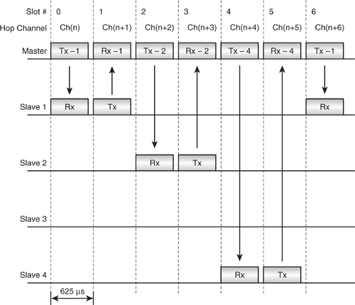
Figure 5–8 shows how a Master is able to communicate with several Slaves in sequence. The Master always transmits on even slots and the Slave replies on odd-numbered slots. The diagram shows ACL traffic where the Master only transmits data when there is something to send. Slave 3 is “missed out”, as there is nothing to send to it at this time. This illustrates the point that a Slave may only transmit if it has been transmitted to, as the Master is able to immediately move on to communicate with Slave 4.
5.5.2 SCO Links
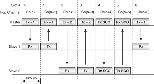
Figure 5–9 shows a Master transmitting to two Slaves, where slots 4 and 5 have been reserved for a SCO link with Slave 2. The other slots are not reserved for SCO, and so the Master can choose which device to transmit ACL traffic to, if at all. Unless the Master is sending LMP traffic to control the Slave 2 link, it must send SCO traffic to Slave 2 in slot 4. Because the SCO slots are reserved, the SCO Slave may reply in the reserved Slot 5 whether or not it detected a packet addressed to itself from the Master.
SCO slots may be spaced to use every slot pair, every second slot pair, or every third slot pair. The spacing of the SCO slots is negotiated when the SCO link is set up, and thereafter those slots are reserved until the SCO link is torn down again. Because the widest spacing for SCO slots is every third slot pair, the maximum number of SCO links which can be supported in a piconet is three. More details on SCO link configuration can be found in Chapter 6.
Figure 5–9 Piconet in operation with SCO traffic.
5.5.3 SCO Links during Inquiry, Paging, and Scanning
As they use reserved capacity, SCO links will continue through inquiry, paging, inquiry scan, and page scan, greatly reducing the opportunity to discover neighboring devices and connect to them.
Figure 5–10 illustrates a SCO slot interrupting inquiry scan to show why SCO reduces the chances of the inquiry succeeding. The diagram shows the timing of the device carrying out the inquiry scan. It must receive an ID packet and respond 625 μs later with an FHS packet. However, it must also regularly receive and transmit SCO packets.
Figure 5–10 Timing of SCO slots during inquiry scan.
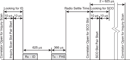
The diagram shows the last moment when an ID packet can arrive and still be responded to before the radio begins to hop onto the frequency for the SCO slot. Any packet arriving after the ID packet shown cannot be responded to without interfering with the reserved SCO slot, thus violating the specification. Not only are the two slots for SCO lost, but also the 625 μs wait for the FHS response, the length of the FHS packet itself, and the time taken for the radio to hop and settle to the required SCO channel frequency. This is because any ID packet received after the one shown in the diagram must be ignored, since the FHS cannot be sent in the time left before the SCO packet must start. In total, the inquiry scan time lost is 2241 μs + the radio settle time, which could add up to another 200 μs. This is made up as follows:
- Two slots for the SCO.
- One slot for the wait to transmit the FHS packet.
- 366 μs FHS packet duration.
- Radio channel synthesiser settle time.
This means that around 60% of the scanning time is lost when a SCO link is present in every third slot pair. If two SCO links are present, using up two slot pairs in three, then over 90% of the scanning time is lost.
The specification recognises that SCO links will interfere with inquiry and suggests that the number of repetitions of the inquiry should be doubled if one slot pair in three is in use by SCO, and trebled if two slots in three are in use by SCO. It also recommends increasing the scan window from the default 11.25 ms in the absence of SCO to 36 ms with one slot pair in three used for SCO and 54 ms for two slot pairs in three used for SCO. However, to make the scanning process reliable, it is preferable to hold the SCO links.
Similar conditions apply in page scanning, except that the longer sequence of packets exchanged during connection setup means that SCO links interfere with paging and page scanning even more than they interfere with inquiry and inquiry scanning.
5.6 Scatternet Operation
A scatternet comprises two (or theoretically more) piconets, where at least one device is active in both. Switching between the piconets requires keeping track of two timebases, as each piconet is synchronised to a different Master’s CLKN. A device which is active in two piconets must maintain and select between two piconet clocks, CLK1 and CLK2, and two access codes, CAC1 and CAC2.
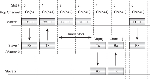
The switch in timebases will require guard time to synchronise to the new timebase, as the piconet’s timings will be asynchronous to each other. In the worst case, they could be a whole slot pair out of sync. This puts a severe limit on how many piconets can be linked together if any meaningful degree of traffic is to be supported on each. SCO makes this especially difficult, as it uses reserved slots. Indeed, only one SCO link using HV3 packets may be active; even then, this only allows one other piconet to be visited in the four slots between the HV3 packets scheduled every six slots. Of the four intervening slots, two are used as guard slots and two are available for traffic in the other piconet.
In Figure 5–11 the top line shows the Master of piconet 1. The middle line shows one of its Slaves, which is also the Master of a second piconet 2; the bottom line shows the Slave on piconet 2. Master 1 transmits to and receives from its Slave in slots 0 and 1. Slave 1 then moves timing onto its own piconet in order to act as Master 2 and transmit to its own Slave. However, due to the difference in timing between the two piconets, it doesn’t have time to retune its radio and transmit, so it waits during slots 2 and 3 before successfully transmitting and receiving in slots 4 and 5. Slave 1/Master 2 may then return immediately to piconet 1 ready for slot 0 again.
Because of the necessity for guard slots created by this difference in slot timings, a device which is present on two piconets will never provide the maximum data bandwidth it would have were it only on one piconet.
Figure 5–11 Scatternet timing.
When a device is busy on another piconet, it can no longer be contacted by its Master and must therefore warn the Master of the periods when it will be away, so that the Master doesn’t think it has lost communication with the Slave altogether. This may be done if the Slave negotiates entry into a low power mode with the Master. In low power modes a device is allowed to switch off for some of the time. (For more information on low power modes please refer to Chapter 17, Low Power Operation.) For a device which will regularly communicate on two piconets, sniff mode is probably the most useful since it allows a device to reduce communication to a regular agreed periodic slot sequence. Of course, in this case, the device is not going to sleep, it is in fact busy talking to someone else.
5.6.1 SCO Links and Scatternets
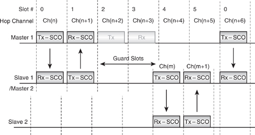
As the widest spacing for SCO slots is every third slot pair, it is not possible for a device to have SCO links in two piconets at once. First of all, the SCO links would need to be synchronised so they were chosen to fit in the time a device could be present on each piconet, yet the Master chooses the timing of the reserved slots, not the Slave, so a Slave cannot force this synchronisation. Second, if the slots happened to fit so that the Slave could switch piconets, and the links were in the right place not to coincide, over time the two piconet clocks would drift until eventually the two SCO links overlapped.
Figure 5–12 shows a SCO link on piconet 1 in slots 0 and 1, while the SCO link for piconet 2 is currently spread across the slots numbered 3 to 5 in piconet 1. At this instant, the SCO slots in the two piconets do not overlap, but as the clocks of the two piconets’ Masters drift, the two SCO links will move until they overlap one another.
Figure 5–12 SCO links in a scatternet.
5.7 Master / Slave Role Switching
Bluetooth allows any device to request a switch in roles with respect to another device it is communicating with. For example, a Master in an existing piconet might allow itself to be paged and connected to a new device and then switch between Slave/Master (temporarily imposed by the paging procedure) and Master/Slave to integrate the new Slave into its piconet. This is accomplished with a Master/Slave switch and is particularly useful in situations where a connection has just been established by a device which normally wishes to be a Slave, such as where a mobile computing device enters a piconet controlled by a LAN access point.
The mechanism essentially involves the Slave sending the difference between its clock and the master’s clock in an LMP message, then asking for a switch and, if accepted, sending an FHS packet to the Master. The Master takes on a CLK offset to match the Slave’s CLKN, while the Slave switches to using its own CLKN, and each device swaps access codes.
5.7.1 Messaging
Figure 5–13 shows the sequence of messages exchanged when a Slave becomes a Master by initiating a Master / Slave switch. The Master side can also request the role switch. The LMP_switch_req message also gives the instant when the switch will happen.
Figure 5–13 Message sequence chart for Master / Slave switch.
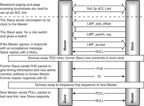
The Slave gives the Master detailed information on its clock, so that the Master can move onto the Slave’s timing. An LMP_slot_offset message is used by the Slave to pass this information to the Master.
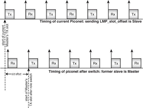
Figure 5–14 illustrates how the slot offset is derived. The Slave knows the timing of its own native clock, and, because it is synchronised to the master, it also knows the timing of the Master’s clock. The Slave works out the instant when a transmit slot starts in the current piconet, then works out how many microseconds it would have to wait for a transmit slot in the piconet timing where it is Master. This value is sent to the current Master of the piconet, along with the BD_ADDR of the Slave which will become Master after the switch.
In version 1.1 of the Bluetooth core specification, the baseband also describes a mechanism by which a Slave which is becoming a master can acquire any other Slaves which belonged to the former Master. The new Master sends an LMP_slot_offset message to tell the Slave the new timing it should use, the Master then sends an FHS, the slave responds with an ID, and both devices move onto the new Master’s hop sequence. The procedure is similar to a Master and Slave’s swapping roles, except that the TDD switch is not needed as the Slave is already on the correct TDD timing.
Figure 5–14 Timing for LMP_slot_offset message.
LMP does not provide any messages to tell the new Master the active member addresses of the old Slaves or to pass on information about Slaves in Hold, Park, or Sniff modes. For the new Master to attempt to acquire the Slaves of the old Master, it has to poll all seven active member addresses using the old Master’s hop sequence and timings and see if any respond.
It is worth noting that the Host Controller interface does not provide commands to control the acquisition of Slaves from a former Master after a role switch.
In practice, the acquisition of Slaves from a Master is unlikely to be a problem, as the main use for a Master/Slave switch is to allow a device to join a piconet quickly by paging, then hand control of piconet back to the former Master of the piconet.
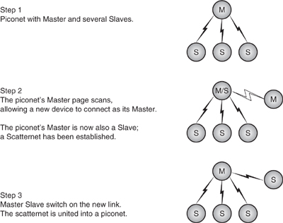
5.7.2 Uniting Scatternets with Role Switch
The devices linking a scatternet are present on more than one piconet and have to time share, spending a few slots on one piconet and a few slots on the other. Each device has its own independent clock, and when devices join a piconet, they track the timing of the piconet’s Master by keeping track of the offset between their clock and the Master’s clock. This means that when devices are present on more than one piconet, they will have to track two sets of timings. When switching between timings, there will be some slots which cannot be used (for a fuller description of scatternet timings and how to manage them, refer to Chapter 18).
Sometimes it is desirable to have a device join a piconet as a Master as shown in Figure 5–15. Consider a LAN Access Point (LAP). It does not know which devices in the area wish to connect, and it would be wasteful of its resources to constantly poll devices to try to connect to them. Instead, it periodically page scans, and any devices wishing to connect page it. This means that connecting devices become Masters of a small piconet containing just themselves and the LAN access point.
If the situation were left like this, the LAN access point would lose control. It must be the Master of its links so that it can control the allocation of bandwidth to the devices connected to it. So, the LAN access point requests a Master / Slave switch as it accepts the connection. The new joiner accepts the switch, and the LAN access point is restored to working in a piconet rather than a scatternet, as shown in Figure 5–15.
Figure 5–15 Forming a scatternet and uniting it into a piconet.
5.8 Low-Power Operation
During Standby, Park, Hold, Sniff, or even between an active transmit or receive operation,2 a device may enter low-power operation, where any protocol or bit processing elements (hardware or software) may be turned off. All system clocks may be disabled, and the device may enter a very low power consumption mode of operation. Certain static data must be maintained, such as LC protocol state and buffer contents, and the only dynamic information which must be maintained is the native clock counter, CLKN. To conserve power, this may be clocked with a much lower power, and therefore less accurate 32 KHz oscillator (÷10 = 3.2 kHz). The tolerance specified in the standard on the Low Power Oscillator (LPO) is ± 250 ppm.
An accuracy of 250 ppm gives rise to a worst case slippage of 1 slot every 2.5 s. This is why regular resynchronisation is important and is explained further in the later section on low-power operation. By way of illustration, the maximum duration for which a device is allowed to remain inactive in Sniff or Hold mode, or between synchronising beacon instants in Park mode, is 40.9 s. This equates to 65,440 slots, which requires an uncertainty window of ± 17 slots.
It is worth noting that 32 kHz crystals are not at present commonplace, unlike the 32.768 kHz crystals commonly used in wristwatches and the like. The tolerance of a quartz crystal does not allow “pulling” over such a large distance, and so we must wait for the commercial success of Bluetooth to create a large demand for 32 kHz parts to force the price of such components down.
5.9 Baseband / Link Controller Architectural Overview
In this short section, we will tie together the material in both the previous chapter and this chapter to examine the overall architecture of a typical Link Controller / Baseband system.
Figure 5–16 shows a possible baseband/Link Controller system. The data path is either SCO (via a direct PCM interface, through HCI) processed by the audio CODEC subsystem, or ACL via HCI. The data is buffered, so it may be read out at system speed subsequently following reception or stored awaiting transmission. Typically, double buffering is used to ease the scheduling of these operations. Indeed, double buffering on transmit is almost essential for a multi-link device where retransmissions must be anticipated.
The data path has already been discussed; it encodes or decodes data bursts during Tx or Rx, respectively. The Rx correlator effectively “sniffs” the received data and, when enabled, will search for the required access code. The sync word generator supplies a valid sync word derived from the appropriate LAP to the radio interface and the correlator as appropriate. The timebase produces a native clock: CLKN from the appropriate system reference clock, which must therefore be accurate to ± 20 ppm. An offset control function then maintains and applies the necessary offsets to produce CLKN, CLK, and CLKE as required.
2When another device’s packet header transmission has been received, indicating a multi-slot packet but with a different AM address, and thus is not directed at the present device.
Figure 5–16 Baseband / LC architecture.
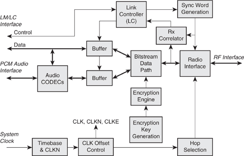
The hop selection function combines the required CLK and BD address parts to produce the channel number and feeds these to the radio interface. Finally, the encryption key generator produces and stores keys, which are then loaded up by the key stream generator and processed at symbol rate to produce a cipher stream for use by the bitstream data path.
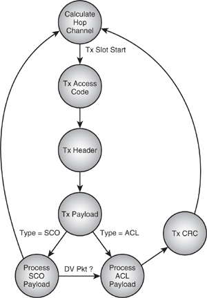
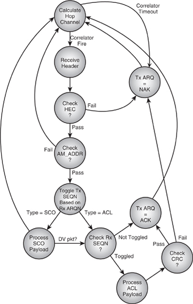
The heart of the system is the Link Controller entity, which controls and sequences the above functions and operations. This typically consists of two main state machines, one for receive and one for transmit. Simplistic examples of these (neglecting aux packets) are shown in Figure 5–17 and Figure 5–18.
The Tx start trigger from the timebase occurs when the CLK counter increments to CLK[1:0] = 00, 01, 10, or 11, depending on whether the device is configured as a Master on whole-slot or half-slot operation or a Slave on whole-slot or half-slot operation, respectively. The Rx start trigger is the correlator match event and of course requires that the radio and correlator have been enabled appropriately some time before the beginning of the uncertainty window. As the diagram shows, the ARQ and SEQ processing is carried out during the receive process and the appropriate values stored, ready for the subsequent transmit operation.
Figure 5–17 LC transmit state machine.
5.10 Summary
The link control layer is responsible for managing device discoverability, establishing connections, and once connected, maintaining the various on-air links. It does this through a set of state machines, which drive the baseband through the following stages to establish links:
- Host requests an inquiry.
- Inquiry is sent using the inquiry hopping sequence.
Figure 5–18 LC receive state machine.
- Inquiry scanning devices respond to the inquiry scan with FHS packets which contain all the information needed to connect with them.
- The contents of the FHS packets are passed back to the host.
- The host requests connection to one of the devices that responded to the inquiry.
- Paging is used to initiate a connection with the selected device.
- If the selected device is page scanning, it responds to the page.
- If the page scanning device accepts the connection, it will begin hopping using the Master’s frequency hopping sequence and timing.
The control of links rests with the local device. Although the Master governs when devices may transmit once connected, it is up to a device to allow itself to be connected with. If a device does not make itself discoverable by inquiry scanning, it cannot be found. If it does not make itself connectable by page scanning, it cannot be linked with, and once in a connection, it is free to disconnect without warning at any time.
Once a baseband link is established, the Master and Slave can exchange roles, so that Slave becomes Master and Master becomes Slave.
The baseband links are used to carry link management traffic, voice traffic (on SCO links), and data traffic (on ACL links).
Mechanisms are also included to support multiple piconets and the exchange of Master and Slave roles between communicating devices, together with several low power periodic operating modes.
The Link Control and Baseband work very closely together, and careful consideration must be given to the overall system design and partitioning for an optimal solution.