A distance sensor is an incredibly useful tool that many modern cars (and few older or budget cars) have. When reversing (and in conjunction with an audible beep sound), immediate feedback as to the distance of an object seriously helps prevent an accident. This could be a child, another car, a wall, or anything. This distance sensor is often called a parking sensor, or parking assist, and it’s the final component of your reversing module. While complex in nature, the sensor circuit handles all the hard work for you, making this project one of the simplest.
Distance Sensor Theory
There are several different ways to detect an object in close proximity to a car. The theory is the same for most of the techniques. Sensors emit some kind of signal. This could be sound, light, or electromagnetic pulses. This signal bounces off nearby objects, and another sensor reads this returning signal. The longer it takes to return, the further away the object is. In practice, it’s a lot more complex than this, but that’s the basic principle. Many cars use a combination of sensors, to detect objects around most of the car. This project only covers one simple sensor, but you could expand it if you so desire.
A common hobby sensor is the ultrasonic range-finder, number HC-SR04P. This cheap component uses soundwaves to detect objects. These work well, and if you’d like to use one, the DistanceSensor class of gpiozero (https://gpiozero.readthedocs.io/en/stable/api_input.html#distancesensor-hc-sr04) handles the work for you. To use this sensor requires three GPIO pins and several resistors arranged together as a voltage divider.
To keep things simple, I’ve chosen to implement an infrared (IR) range sensor using the KY-032 module. Everything you need is included in the hardware module, and it’s extremely simple to wire up and code – especially if you’ve completed the previous project chapters. These sensors cost a few dollars and are available from Amazon or your local electronics store.
This sensor emits an infrared light, which bounces off nearby objects back into the infrared detector. It’s already fine-tuned to the specific wavelengths required and comes with its own integrated circuit to handle the transmission for you. It has a maximum range of roughly 15 inches – which may not match commercial car sensors – but it’s about on par with the ultrasonic range-finder and is fairly standard for consumer sensors in this price range.
Distance Sensor Hardware
Always turn off and disconnect the Pi’s power supply when working with electronic circuits.
To build this project, you’ll need a KY-032 IR sensor module. These come in several minor variants. You’ll run this at 3.3v, but almost all of the modules available operate at 3.3v–5v. Make sure you double-check. Running at a lower voltage than required won’t break it, but it may not work correctly, if at all. Most units come with four connection pins and a jumper header to reconfigure the circuit. Alternatively, a three-pin model also exists, which provides the exact same functionality.

KY-032 IR sensor module
The left status LED is labelled as “PLED”. This stands for power LED. It lights up to indicate that the module has power. The LED on the right is labelled as “SLED”, which stands for status LED. This lights up when there is an obstruction detected by the sensor. When clear, it turns off again.
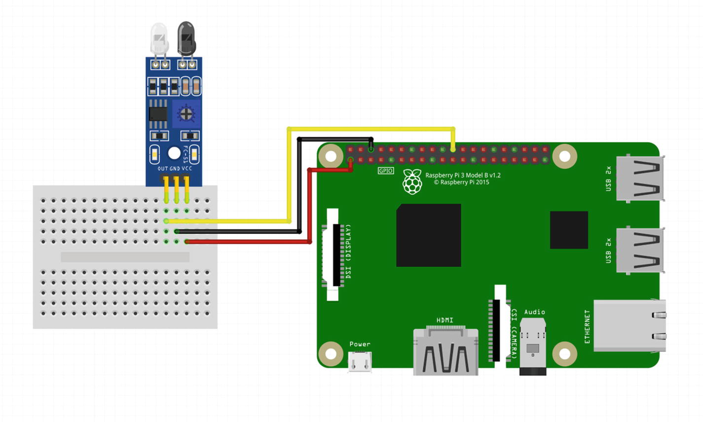
KY-032 IR sensor wiring diagram
GND
+
Out
EN
Connect the Pi’s ground to GND. Connect the Pi’s 3.3v to +. Connect physical pin 22 (GPIO pin 25) to Out. This is where the Pi will read the sensor state. The final pin, marked EN, is an enable pin. You can optionally use this to trigger sensor pings. By default, the module automatically sends out sensor pings, configured using the jumper on the lower right. You can ignore this pin. The wiring diagram is shown in Figure 13-2.
Once ready, connect the power supply and boot the Pi.
Distance Sensor Flask Code
This sensor is very easy to code for. It produces a HIGH or LOW signal, depending on object detection – much like a button. If an object is detected within range, the SLED status LED lights up, and the sensor returns a HIGH value. If no object is detected, the Pi’s pull-down resistor is detected by the GPIO pin as LOW. For this reason, you can use the Button class and your existing logic to read this data.
Once verified on your machine, commit your code and perform a build. Load the main page at http://pi-car:500 and check the result under the rear_distance key. Reload the page several times while covering and uncovering the sensor.
Chapter Summary
In this chapter you build a rear distance sensor using an IR module. You learned the differences between several different rear sensing techniques and the pitfalls of consumer-level sensors. You coded around some potentially confusing logic introduced by a third-party library and continued to expand your application with clean, documented, and easy-to-read code.
Well done! You now have everything in place to finish configuring your car dashboard system. In the next chapter, I’ll cover bringing everything together into a functional and usable system and performing final polishing and system tuning.